Sélection de la langue

Search

Sommaire du brevet 2150817 

Énoncé de désistement de responsabilité concernant l'information provenant de tiers

Une partie des informations de ce site Web a été fournie par des sources externes. Le gouvernement du Canada n'assume aucune responsabilité concernant la précision, l'actualité ou la fiabilité des informations fournies par les sources externes. Les utilisateurs qui désirent employer cette information devraient consulter directement la source des informations. Le contenu fourni par les sources externes n'est pas assujetti aux exigences sur les langues officielles, la protection des renseignements personnels et l'accessibilité.

Disponibilité de l'Abrégé et des Revendications

L'apparition de différences dans le texte et l'image des Revendications et de l'Abrégé dépend du moment auquel le document est publié. Les textes des Revendications et de l'Abrégé sont affichés :

  • lorsque la demande peut être examinée par le public;
  • lorsque le brevet est émis (délivrance).
(12) Brevet: (11) CA 2150817
(54) Titre français: DISPOSITIF D'HOMOGENEISATION DE FLUIDES TRES VISQUEUX
(54) Titre anglais: DEVICE FOR HOMOGENISING HIGHLY VISCOUS FLUIDS
Statut: Réputé périmé
Données bibliographiques
(51) Classification internationale des brevets (CIB):
  • B01F 5/06 (2006.01)
  • B01F 3/10 (2006.01)
  • B29C 45/58 (2006.01)
(72) Inventeurs :
  • SIGNER, ARNO (Suisse)
(73) Titulaires :
  • SULZER CHEMTECH AG (Suisse)
(71) Demandeurs :
(74) Agent: GOWLING WLG (CANADA) LLP
(74) Co-agent:
(45) Délivré: 1997-07-01
(86) Date de dépôt PCT: 1994-09-30
(87) Mise à la disponibilité du public: 1995-04-13
Requête d'examen: 1995-06-01
Licence disponible: S.O.
(25) Langue des documents déposés: Anglais

Traité de coopération en matière de brevets (PCT): Oui
(86) Numéro de la demande PCT: PCT/CH1994/000195
(87) Numéro de publication internationale PCT: WO1995/009689
(85) Entrée nationale: 1995-06-01

(30) Données de priorité de la demande:
Numéro de la demande Pays / territoire Date
93810701.8 Office Européen des Brevets (OEB) 1993-10-05

Abrégés

Abrégé français

Un dispositif d'homogénéisation de fluides très visqueux comprend des mélangeurs statiques (11, 12) et, le cas échéant, des éléments de filtrage (6). Ces éléments constitutifs du dispositif sont montés dans une douille (13) le long de l'axe (15) de la douille. La douille est constituée de plusieurs parties et les éléments constitutifs du dispositif forment des composants monolithiques (10, 20; 60). Plusieurs ou tous ces composants ont des parties (4; 4a, 4b) similaires à des rebords ou à des becs. Les composants sont ancrés dans la zone de la douille située entre les parties de la douille par ces parties similaires à des rebords ou à des becs et constituent en même temps des parties de la douille. Ce dispositif est utilisé par exemple comme tête mélangeuse (1) dans la filière d'une machine à couler par injection ou comme mélangeur de la masse fondue dans une extrudeuse.


Abrégé anglais


A device for homogenising highly viscous fluids has static mixing elements
(11, 12) and if required filtering elements (6). These elements of the device
are arranged in a sleeve (13) along the axis (15) of the sleeve. The sleeve is
made of several parts and the elements that make up the device are monolithic
components (10, 20; 60). Many or all components have flange- or nose-like
parts (4; 4a, 4b) with which they are anchored in the area of the sleeve
located between the parts that make up the sleeve and at the same time form
parts of the sleeve. This device is suitable for example as mixing head (1) in
the nozzle of an injection casting machine or as molten mass mixer in an
extruder.

Revendications

Note : Les revendications sont présentées dans la langue officielle dans laquelle elles ont été soumises.


7
CLAIMS

1. A device for the homogenisation of high-viscosity fluids
comprising static mixing elements, the elements being arranged in a sleeve
along the sleeve axis, the sleeve being composed of several parts, the elements
of the device being monolithic structural members and at least a plurality of
these structural members being flange-like or nose-like parts which engage so
as to anchor in the sleeve region between sleeve parts and to form, at the
same time, parts of the sleeve.

2. A device according to Claim 1 characterized in that each
flange-like part is ring-shaped and extends perpendicularly to the sleeve axis.

3. A device according to Claim 1 characterised in that a flange-like
part is situated in the middle region of all or some of the monolithic structural
members.

4. A device according to Claim 1 characterised in that a rib forms the
respective nose-like part in all or some of the monolithic structural members,
the ribs extending parallel to the sleeve axis.

5. A device according to Claim 1 characterised in that the mixing
elements comprise a plurality of longitudinally arranged webs, the webs of
adjacent layers crossing each other and the webs being disposed, with respect
to the sleeve axis, a unitary angle of between 10 and 70°.

6. The device of Claim 5, wherein the unitary angle is about 45°.

7. A device according to Claim 1, further comprising at least one
filter element.

8. A device according to Claim 7 characterised in that the filter
element is a rib filter.

8
9. A device according to any one of Claims 1 to 8 characterised in
that the monolithic structural members are of a metallic alloy and are made by
precision casting or sinter injection moulding.

10. A device according to any of Claims 1 to 8 characterised in that
the monolithic structural members are of plastics.

11. A device according to any of Claims 1 to 8 characterised in that
the monolithic structural members are of plastics.

12. Use of a device according to any of Claims 1 to 8 as a mixed head
in the nozzle of an injection moulding machine or as a melt mixer downstream
of the screw of an extruder.

Description

Note : Les descriptions sont présentées dans la langue officielle dans laquelle elles ont été soumises.

- 21S0817
~6600

DEVICE FOR THE HOMOGENIZATION OF HIGH-VISCOSITY FLUIDS

The invention relates to a device for the homogenization
of high-viscosity fluids according to the preamble of
Claim 1 and also to uses of such a device.

During the extrusion and injection moulding of
thermoplastic materials homogenous - particularly
thermally homogenous - melts are produced using static
- mixers. Without special provisions plastics melts in
plastification machines on leaving the screw exhibit
considerable temperature differences; when colouring
agents and/or additives are added also their distribution
is irregular. In injection moulding machines the
necessary homogeneity of the plastics melt is obtained by
the provision of a mixing head in the nozzle (see e.g.
G. Schneider and R. Maurer, Osterr. Kunststof f-
Zeitschrift, 1985, pages 86-89).

A mixing head or melt mixer comprises a sleeve in which
are situated several mixing elements. Due to the high
viscosity of plastics melts large forces act on the
mixing elements and also between the mixing elements and
the sleeve. In a preferred embodiment of the mixing
head, the mixing elements are in the form of a casting
which is monolithic (i.e. cohesive without joints) and is
soldered into the sleeve. Such a mixing head has
naturally the disadvantage that in extreme conditions the
soldered joint may not survive. Such extreme conditions
which may arise during faulty operation are, for
instance: cold start (with a peak pressure of around 2000
bar), fast heating, cleaning with a naked flame,
quenching at an annealing temperature with water.

The aim of the invention is to provide a device for the

2150~17
-


homogenization of high-viscosity fluids - for instance a
mixing head or a melt mixer - which remains, as far as
possible, indestructible in extreme conditions. Such
device should be also able to be well cleaned. The device
should comprise, in addition to static mixing elements,
possibly also a filter element, for instance a rib
filter. In claim 1 are listed the characterising features
by which the aim of the invention is achieved. The term
"monolithic structural member" is intended to mean a
structural element which has no weaknesses caused by
joints - for instance soldered joints (while on the other
hand a structural member with weld joints may be
monolithic). The sleeve parts mentioned in claim 1
comprise in an extreme case only the flange-like parts
which are, in this case, tubular.

The dependent claims 2 to 9 relate to preferred
embodiments of the device according to the invention. The
independent claim 10 relates to the use of this device.

The invention will now be explained in greater detail
with reference to the drawings, in which:

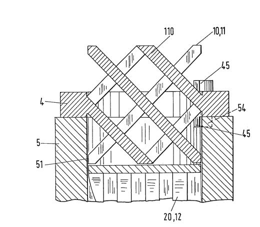
Fig. 1 is a cross-section of the nozzle of an
injection moulding machine having a mixing head
of a known design,

Fig. 2 is a mixing head according to the invention,

Fig. 3 is a mixing element of a device according to
the invention,

Fig. 4 is a second embodiment of a mixing element
according to the invention,

-


2150817


Fig. 5 is a cross-section of the mixing element of
Fig. 4,
Figs 6,7 are further variants of mixing elements,
Fig. 8 is a rib filter element for a device according
to the invention, and
Fig. 9 shows a monolithic structural member of a
device according to the invention with two
mixing elements.

The nozzle 2 shown in Fig. 1 has the following
components: a mixing head 1 with static mixing elements
11, 12 and a sleeve 13; a nozzle head 21 with a nozzle
orifice 22 and a bore 23 for the mixing head 1; by chain
lines is indicated a strip heater 24; and finally the tip
of an extruder screw 3. Fig. 2 shows a side elevation of
a mixing head 1 according to the invention which does not
have a one-piece sleeve 13, as in the known design, but
has a composite sleeve comprising parts 4 and 5. The
part 4 forms, together with the mixing element 11, a
monolithic structural member 10. Fig. 3 shows a first
embodiment: The part 4 is a flange-like part of the
structural member 10 by means of which this part is
anchored between the sleeve parts 5. The part 4 is ring-
shaped and situated perpendicularly to a sleeve axis 15;
in the illustrated example the part 4 is situated in the
middle of the mixing element 11. The mixing element 11
is composed of layers 101 of pleated lamellae between
which are situated, due to be pleating, channels which
often cross each other. The circle 102, drawn in a chain
line, indicates the outer outline of the end face.

The monolithic structural member 10 shown in Fig. 4 has

~ c
.~
.,p

~- 21~0817


also a flange like part 4 which is ring-shaped and is
situated in the middle of the mixing element 11. The
flange-like part 4 is partly broken away to show that the
structural member 10 is monolithic. The mixing element
11 comprises a plurality of longitudinally arranged webs
110. The webs 110 of adjacent layers cross each other;
they make with the sleeve axis 15 an angle of 45 (this
angle can also assume values between 10 and 70).

Fig. 5 shows in cross-section the structural member 10 of
Fig. 4, a portion of a tubular sleeve part 5 and a
monolithic structural member 20 which is adjacent to the
structural member 10 and comprises a mixing element 12.
Between the sleeve part 5 and the webs 110 may be a gap
51. In contrast to what is shown, the outer diameter of
the sleeve part 5 and the outer diameter of the ring 4
can naturally have the same dimension. On the ring 4 are
provided bosses 45 and on the sleeve part 5 are provided
corresponding recesses 54 by means of which may be preset
firm alignment of the structural member 10 with respect
to the adjacent structural member 20.

The structural members 10 and the sleeve parts 5 are only
fitted together (connections between the parts by mating
shapes). The parts may therefore be easily separated
from each other, which meets also the requirement that
the device according to the invention must be able to be
easily cleaned.

Fig. 6 shows a variant of the structural element 10 in
which the mixing element 11', shown by chain lines, is
cube-shaped or cuboid-shaped. In addition to the mixing
element types shown in Figs. 3 and 4 also other known
types may be used in principle (see e.g. M.H. Pahl and e.
Muschelknautz, Chem.-Ing.-Tech. 52, 1980, p. 285-291,

.~ .
~..P~

-
2150817


particularly Fig. ld).

In the structural member 10 shown in Fig. 7 two ribs 4a
and 4b (also referred to as "nose-like parts") provide
the anchoring in the sleeve. The end face 140 is an
annular sector which lies within the central angle ~
(with the sleeve axis 15 as the centre). The volume of
this angle is, for instance, 60. With the structural
member 10 may be associated a sleeve part 5 comprising a
thin-walled tube 50 and two parts 51a and 51b, which are
shaped complimentary to the space between the ribs 4a and
4b.

If the melt to be homogenised comprises impurities in the
form of particles it is recommended to provide in the
device, according to the invention, additionally a filter
element. An example of such filter element - namely a
rib filter 6 - is shown in Fig. 8. Through supply
channels 61 arrives the melt into axial distribution
channels 62 and flows from there, over the ribs 64, into
collection channels 63. The ribs 64 form together with
sleeve parts (not shown) narrow passages by which the
particles of impurities are retained in the distribution
channels 62. The channels 62 are at their ends closed by
a ring 65; the channels 63 remain partly open so that the
melt may flow further, for instance into the downstream
situated mixing elements. The filter element 6 and the
ring 4 form, even in this case, a monolithic structural
element 60.

Figure 9 shows finally that always two adjacent mixing
elements 11 and 12 are combined to form a monolithic
structural member 30. This pair of elements has a common
flange-like part 4 which ensures anchoring between sleeve
parts.

"~

215081 7


For use as a mixing head or a melt mixer the monolithic
structural members 10, 20, 30, 60 are preferably made of
a metallic alloy by precision casting (preferably) or by
sinter injection moulding. For other applications it may
be recommendable to make these structural members of a
ceramic material or even of plastics

Dessin représentatif
Une figure unique qui représente un dessin illustrant l'invention.
États administratifs

Pour une meilleure compréhension de l'état de la demande ou brevet qui figure sur cette page, la rubrique Mise en garde , et les descriptions de Brevet , États administratifs , Taxes périodiques et Historique des paiements devraient être consultées.

États administratifs

Titre Date
Date de délivrance prévu 1997-07-01
(86) Date de dépôt PCT 1994-09-30
(87) Date de publication PCT 1995-04-13
(85) Entrée nationale 1995-06-01
Requête d'examen 1995-06-01
(45) Délivré 1997-07-01
Réputé périmé 2013-10-01

Historique d'abandonnement

Il n'y a pas d'historique d'abandonnement

Historique des paiements

Type de taxes Anniversaire Échéance Montant payé Date payée
Le dépôt d'une demande de brevet 0,00 $ 1995-06-01
Enregistrement de documents 0,00 $ 1996-01-04
Taxe de maintien en état - Demande - nouvelle loi 2 1996-09-30 100,00 $ 1996-08-20
Taxe de maintien en état - brevet - nouvelle loi 3 1997-09-30 100,00 $ 1997-08-18
Taxe de maintien en état - brevet - nouvelle loi 4 1998-09-30 100,00 $ 1998-08-24
Taxe de maintien en état - brevet - nouvelle loi 5 1999-09-30 150,00 $ 1999-08-13
Taxe de maintien en état - brevet - nouvelle loi 6 2000-10-02 150,00 $ 2000-08-14
Taxe de maintien en état - brevet - nouvelle loi 7 2001-10-01 150,00 $ 2001-08-17
Taxe de maintien en état - brevet - nouvelle loi 8 2002-09-30 150,00 $ 2002-08-15
Taxe de maintien en état - brevet - nouvelle loi 9 2003-09-30 150,00 $ 2003-08-19
Taxe de maintien en état - brevet - nouvelle loi 10 2004-09-30 250,00 $ 2004-08-23
Taxe de maintien en état - brevet - nouvelle loi 11 2005-09-30 250,00 $ 2005-08-25
Taxe de maintien en état - brevet - nouvelle loi 12 2006-10-02 250,00 $ 2006-08-24
Taxe de maintien en état - brevet - nouvelle loi 13 2007-10-01 250,00 $ 2007-08-23
Taxe de maintien en état - brevet - nouvelle loi 14 2008-09-30 250,00 $ 2008-08-25
Taxe de maintien en état - brevet - nouvelle loi 15 2009-09-30 450,00 $ 2009-09-17
Taxe de maintien en état - brevet - nouvelle loi 16 2010-09-30 450,00 $ 2010-09-16
Taxe de maintien en état - brevet - nouvelle loi 17 2011-09-30 450,00 $ 2011-09-16
Titulaires au dossier

Les titulaires actuels et antérieures au dossier sont affichés en ordre alphabétique.

Titulaires actuels au dossier
SULZER CHEMTECH AG
Titulaires antérieures au dossier
SIGNER, ARNO
Les propriétaires antérieurs qui ne figurent pas dans la liste des « Propriétaires au dossier » apparaîtront dans d'autres documents au dossier.
Documents

Pour visionner les fichiers sélectionnés, entrer le code reCAPTCHA :


Pour visualiser une image, cliquer sur un lien dans la colonne description du document. Pour télécharger l'image (les images), cliquer l'une ou plusieurs cases à cocher dans la première colonne et ensuite cliquer sur le bouton "Télécharger sélection en format PDF (archive Zip)" ou le bouton "Télécharger sélection (en un fichier PDF fusionné)".

Liste des documents de brevet publiés et non publiés sur la BDBC .

Si vous avez des difficultés à accéder au contenu, veuillez communiquer avec le Centre de services à la clientèle au 1-866-997-1936, ou envoyer un courriel au Centre de service à la clientèle de l'OPIC.


Description du
Document 
Date
(yyyy-mm-dd) 
Nombre de pages   Taille de l'image (Ko) 
Revendications 1995-11-09 2 58
Page couverture 1995-11-09 1 18
Page couverture 1997-05-07 1 14
Abrégé 1995-11-09 1 21
Dessins 1995-11-09 3 124
Description 1995-11-09 6 209
Abrégé 1997-05-07 1 22
Description 1997-05-07 6 213
Revendications 1997-05-07 2 51
Dessins 1997-05-07 3 125
Page couverture 1995-11-01 1 18
Abrégé 1995-04-13 1 21
Description 1995-04-13 6 209
Revendications 1995-04-13 2 58
Dessins 1995-04-13 3 124
Dessins représentatifs 1999-06-14 1 25
Taxes 1996-08-20 1 36
Correspondance 1996-12-10 1 78
Correspondance 1996-01-04 1 28
Correspondance 1995-06-01 1 28
Cession 1995-06-01 6 241
PCT 1995-06-01 17 697
Correspondance 1997-03-27 1 34
Poursuite-Amendment 1995-08-21 2 50