Sélection de la langue

Search

Sommaire du brevet 2151130 

Énoncé de désistement de responsabilité concernant l'information provenant de tiers

Une partie des informations de ce site Web a été fournie par des sources externes. Le gouvernement du Canada n'assume aucune responsabilité concernant la précision, l'actualité ou la fiabilité des informations fournies par les sources externes. Les utilisateurs qui désirent employer cette information devraient consulter directement la source des informations. Le contenu fourni par les sources externes n'est pas assujetti aux exigences sur les langues officielles, la protection des renseignements personnels et l'accessibilité.

Disponibilité de l'Abrégé et des Revendications

L'apparition de différences dans le texte et l'image des Revendications et de l'Abrégé dépend du moment auquel le document est publié. Les textes des Revendications et de l'Abrégé sont affichés :

  • lorsque la demande peut être examinée par le public;
  • lorsque le brevet est émis (délivrance).
(12) Brevet: (11) CA 2151130
(54) Titre français: SUPPRESSEUR DE SURTENSION COMPRENANT UNE RESISTANCE A OXYDE METALLIQUE
(54) Titre anglais: OVERVOLTAGE SUPPRESSOR WITH A METAL OXIDE RESISTOR
Statut: Réputé périmé
Données bibliographiques
(51) Classification internationale des brevets (CIB):
  • H01C 7/12 (2006.01)
(72) Inventeurs :
  • KIRCH, JOHANNES (Allemagne)
  • LEUSCHNER, HANS (Allemagne)
(73) Titulaires :
  • SIEMENS AKTIENGESELLSCHAFT (Allemagne)
(71) Demandeurs :
(74) Agent: FETHERSTONHAUGH & CO.
(74) Co-agent:
(45) Délivré: 1998-05-26
(86) Date de dépôt PCT: 1993-12-02
(87) Mise à la disponibilité du public: 1994-06-23
Requête d'examen: 1995-06-06
Licence disponible: S.O.
(25) Langue des documents déposés: Anglais

Traité de coopération en matière de brevets (PCT): Oui
(86) Numéro de la demande PCT: PCT/DE1993/001159
(87) Numéro de publication internationale PCT: WO1994/014171
(85) Entrée nationale: 1995-06-06

(30) Données de priorité de la demande:
Numéro de la demande Pays / territoire Date
G 92 17 133.8 U Allemagne 1992-12-08

Abrégés

Abrégé français

Dans un limiteur de surtension présentant un arrangement multi-colonnes de résistances à oxyde métallique placées dans un boîtier isolant, chaque colonne est constituée d'éléments de résistance faisant partie d'une structure mécaniquement autoportante. Les éléments de résistance de chaque colonne sont disposés dans ce but entre deux plaques de soutien interreliées par des tiges de fixation. Les colonnes particulières, que l'on appelle des modules, sont disposées de manière ce que chacune d'entre elles se trouve au centre d'une plaque adaptée à l'extrémité inférieure du boîtier isolant.


Abrégé anglais


In an overvoltage suppressor with a multi-column
arrangement of the metal oxide resistors within an
insulating housing, each column is to be made of
resistance elements in a mechanically self-supporting
structure. To this end, the resistance elements of each
column are arranged between two holding plates interconnected
by holding rods. The individual columns, called
"modules", are arranged to be individually centered on a
plate fitted at the lower end of the insulating housing.


Revendications

Note : Les revendications sont présentées dans la langue officielle dans laquelle elles ont été soumises.


THE EMBODIMENTS OF THE INVENTION IN WHICH AN EXCLUSIVE
PROPERTY OR PRIVILEGE IS CLAIMED ARE DEFINED AS FOLLOWS:

1. An overvoltage suppressor with an insulating housing
having a metal oxide resistor arranged inside the insulating
housing, such that the metal oxide resistor consists of two or
more electrically parallel connected columns, which are made
up of a larger number of resistance elements, of which each
column has two separate holding plates between which the
resistance elements of the column are arranged, and which in
turn are joined by means of insulating holding rods which
laterally immobilize the resistance elements,
wherein the columns are arranged at the lower end of the
insulating housing on a plate, centered with respect to the
axis of the insulating housing, wherein a separate compression
spring is associated with each of the columns for contact
purposes.

2. An overvoltage suppressor according to claim 1,
wherein the holding plates are triangular in shape.


- 5 -

Description

Note : Les descriptions sont présentées dans la langue officielle dans laquelle elles ont été soumises.


21 51 1 30


uv~KvOLTAGE ~u~rK~SOR WITH A METAL OXIDE RESISTOR

Bac~qround of the Invention
The invention, which is in the area of protective
engineering for energy distribution facilities, is
concerned with the structural configuration of an
overvoltage suppressor, with an insulating housing and
with a metal oxide resistance arranged inside the
insulating housing, such that the metal oxide resistor
consists of two or more columns, connected electrically
in parallel, made up of a larger number of resistance
elements, of which each column has two separate holding
plates between which the resistance elements of the
column are arranged, and which in turn are joined by
means of insulating holding rods which laterally
immobilize the resistance elements.

Overvoltage suppressors with a metal oxide resistor
as the shunting element generally consist of a plurality
of flat cylindrical resistance elements arranged in
columnar fashion one above the other, the column formed
by these resistance elements being arranged inside a
ceramic or plastic insulator tightly sealed at the top


SUB~ .u.~ ~PECIFICATION

.,

2 2151 ~30
and b~ottom ("IEEE Transactions on Power Delivery," Volume
PWRD-l, No. 1, January 1986, pp. 151-156; Figure 6).

To increase the energy handling capacity or to
reduce the residual voltage, it is common in the case of
metal oxide shunts to connect a plurality of resistance
columns made up of individual resistance elements in
electrically parallel fashion. For this purpose, two to
four columns are arranged next to one another, inside a
common insulating housing, on a support plate by means of
which they are inserted into the common housing. This is
known, for example, from US Patent Number 4,326,232.

- Summarv of the Invention
The invention creates an overvoltage suppressor
structure which improves the individual columns in terms
of handling and accessibility for measurement purposes.
Proc~;ng from an overvoltage suppressor with the
features of the preamble of Claim 1, the columns are
arranged at the lower end of the insulating housing on a
- plate, centered with respect to the axis of the
insulating housing, and a separate compression spring is
associated with each of the columns for contact purposes.

A configuration of this kind thus provides for each
individual column, made up of resistance elements, to
constitute an independent module which represents a
mechAn~cally self-supporting structure. The particular
required number of these modules is placed next to one
another in the insulating housing, and mechanically and
electrically joined together and immobilized at both ends
by suitable structural means. The assembly of multiple
modules, st~Ardized in this fashion and completely
identical to one another, yields a substantial
simplification in production. In particular, the

SUB~ '. u .~i SPECIFICATION

3 2151 130

individual modules are easy to handle during assembly of
the overvoltage suppressor. Furthermore, it is possible
to evaluate the individual modules before complete
assembly of the overvoltage suppressor, and thus
determine current distribution. With reference to the
operation of this kind of overvoltage suppressor,
separate construction of the individual resistance
- columns allows displacement of the modules with respect
to one another when the suppressor is overloaded, thus
opening up a pressure relief channel of the greatest
possible cross section in the region of the active arc.
This displaceability can be ensured by suitable
structural measures at the top end - and, if necessary,
- also at the bottom end - of the individual columns.
Because contact with each individual resistance
column is made by a separate compression spring, a
contact pressure of substantially equal magnitude, and
thus a transition resistance of equal magnitude, is
achieved for all the modules.

Brief Description of the Drawings
An exemplary embodiment of the invention is depicted
in Figures 1 and 2, in which:
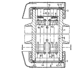
Figure 1 shows a vertical section of the housing
with a view of the suppressor element; and

Figure 2 shows a cross section through the
suppressor in the region of the lower end.

Detailed De~cription
Figure 1 shows an overvoltage suppressor whose
housing consists, in a known manner, of ceramic insulator
1 and a metal foot part 2 and a metal head part 3. The

8~B~ u.~ 8PECIFICATION

2 1 5 1 1 30


housing could also be made of a plastic. Arranged at the
lower end of ceramic insulator 1 is a plate 4 in the form
of a bearing bracket, which is immobilized by means of a
mounting ring 41, such that this mounting ring also
immobilizes a membrane 42 and a sealing ring 43. Also
joined to plate 4 iS a superposed cruciform web member
44, on which the columnar resistance modules 6 are
braced. These modules consist of a plurality of
resistance elements 64, arranged one on top of another,
which are located between the lower holding plate 61 and
upper holding plate 62, the holding plates being joined
together by means of three holding rods 63 arranged with
uniform spacing at the circumference. Fastened in each
case to the lower holding plate 61 iS a block-like spacer
5, by means of which the respective columnar module 6 is
positively centered in the cruciform web member 44.

Also arranged on the upper holding plate 62 is a
spacer 7 on which a compression spring 8 rests. Also
20 provided, in shared fashion for all columnar modules 6,
is a contact plate 9 which is placed under pressure, with
the interposition of pressure pieces 10, by pressure ring
11 joined to head part 3, and by pressure plate 13.
Pressure plage 13 further serves to immobilize the upper
25 membrane 12 and associated sealing ring.

According to Figure 4, four columnar modules 6 are
arranged inside ceramic insulator 1. Holding plates 61
and 62 of the modules are triangular in shape, in order
to ensure the least possible radial expansion of the
overvoltage suppressor as a whole.


8UB~ u~ SPECIFICATION

Dessin représentatif
Une figure unique qui représente un dessin illustrant l'invention.
États administratifs

Pour une meilleure compréhension de l'état de la demande ou brevet qui figure sur cette page, la rubrique Mise en garde , et les descriptions de Brevet , États administratifs , Taxes périodiques et Historique des paiements devraient être consultées.

États administratifs

Titre Date
Date de délivrance prévu 1998-05-26
(86) Date de dépôt PCT 1993-12-02
(87) Date de publication PCT 1994-06-23
(85) Entrée nationale 1995-06-06
Requête d'examen 1995-06-06
(45) Délivré 1998-05-26
Réputé périmé 2005-12-02

Historique d'abandonnement

Il n'y a pas d'historique d'abandonnement

Historique des paiements

Type de taxes Anniversaire Échéance Montant payé Date payée
Le dépôt d'une demande de brevet 0,00 $ 1995-06-06
Taxe de maintien en état - Demande - nouvelle loi 2 1995-12-04 100,00 $ 1995-11-27
Enregistrement de documents 0,00 $ 1995-12-21
Taxe de maintien en état - Demande - nouvelle loi 3 1996-12-02 100,00 $ 1996-11-22
Taxe de maintien en état - Demande - nouvelle loi 4 1997-12-02 100,00 $ 1997-11-18
Taxe finale 300,00 $ 1998-02-18
Taxe de maintien en état - brevet - nouvelle loi 5 1998-12-02 150,00 $ 1998-11-16
Taxe de maintien en état - brevet - nouvelle loi 6 1999-12-02 150,00 $ 1999-11-15
Taxe de maintien en état - brevet - nouvelle loi 7 2000-12-04 150,00 $ 2000-11-16
Taxe de maintien en état - brevet - nouvelle loi 8 2001-12-03 150,00 $ 2001-11-22
Taxe de maintien en état - brevet - nouvelle loi 9 2002-12-02 150,00 $ 2002-11-22
Taxe de maintien en état - brevet - nouvelle loi 10 2003-12-02 200,00 $ 2003-11-13
Titulaires au dossier

Les titulaires actuels et antérieures au dossier sont affichés en ordre alphabétique.

Titulaires actuels au dossier
SIEMENS AKTIENGESELLSCHAFT
Titulaires antérieures au dossier
KIRCH, JOHANNES
LEUSCHNER, HANS
Les propriétaires antérieurs qui ne figurent pas dans la liste des « Propriétaires au dossier » apparaîtront dans d'autres documents au dossier.
Documents

Pour visionner les fichiers sélectionnés, entrer le code reCAPTCHA :


Pour visualiser une image, cliquer sur un lien dans la colonne description du document. Pour télécharger l'image (les images), cliquer l'une ou plusieurs cases à cocher dans la première colonne et ensuite cliquer sur le bouton "Télécharger sélection en format PDF (archive Zip)" ou le bouton "Télécharger sélection (en un fichier PDF fusionné)".

Liste des documents de brevet publiés et non publiés sur la BDBC .

Si vous avez des difficultés à accéder au contenu, veuillez communiquer avec le Centre de services à la clientèle au 1-866-997-1936, ou envoyer un courriel au Centre de service à la clientèle de l'OPIC.


Description du
Document 
Date
(yyyy-mm-dd) 
Nombre de pages   Taille de l'image (Ko) 
Page couverture 1995-10-31 1 19
Abrégé 1994-06-23 1 16
Description 1994-06-23 4 142
Dessins 1994-06-23 1 41
Revendications 1994-06-23 1 24
Page couverture 1998-05-13 1 49
Abrégé 1997-04-30 1 16
Description 1997-04-30 4 160
Revendications 1997-04-30 1 29
Dessins représentatifs 1998-05-13 1 14
Correspondance 1998-02-18 1 31
Taxes 1996-11-22 1 78
Taxes 1995-11-27 1 67
Lettre du bureau 1997-03-20 1 39
Demande d'entrée en phase nationale 1995-06-29 2 93
Demande d'entrée en phase nationale 1995-06-06 2 109
Correspondance de la poursuite 1995-06-06 1 32
Rapport d'examen préliminaire international 1995-06-06 26 911
Correspondance de la poursuite 1995-06-06 8 243
Demande d'examen 1996-11-19 1 52