Note : Les descriptions sont présentées dans la langue officielle dans laquelle elles ont été soumises.
CA 02152049 2001-08-31
1
TELEMETRY SYSTEM AND APPARATUS
Field of Invention
This invention relates to a telemetry system and to a
method for recovering data from an auditory prosthesis.
Background Art
After an auditory prosthesis, such as a cochlear
prosthesis, is surgically implanted, it is advantageous if data
can be obtained about the actual performance of the electrode
array, and the response of the auditory nerve to stimulation.
This enables detection or confirmation of normal operation of
the device, and optimisation of stimulus parameters in an
objective fashion. Similar requirements apply to other
implanted auditory prostheses.
It is an object of the present invention to provide a
telemetry system for an auditory prosthesis such that the
required data may be effectively, and with minimal inconvenience
to a patient, monitored externally.
Summary of Invention
According to one aspect the present invention comprises
an auditory prosthesis including an array comprising a plurality
of intra-cochlear electrodes coupled to an amplifier which is
controlled by switching means via a processor characterised by
means for telemetering the response of nervous tissue to
stimulation by said auditory prosthesis, the processor being
arranged to control the switching means to select electrodes of
said array to deliver stimulation current and, after delivery of
said stimulation current, to open-circuit said plurality of
electrodes, thereby reducing stimulus artefact due to said
stimulation current, said amplifier being arranged to detect a
neural response potential across a selected pair of electrodes,
wherein said potential is indicative of at least one parameter
of response by said neural system.
After said electrical stimulus, all electrodes are open
circuited for a predetermined period prior to said potential
being detected. Preferably means are provided for nulling said
amplifier. Preferably said means for nulling nulls said
CA 02152049 2001-08-31
2
amplifier during said predetermined period. Preferably said
means for nulling nulls a plurality of cascaded gain stages of
said amplifier, wherein at the end of said period said stages
are released sequentially such that any offset voltage is
substantially cancelled.
Preferably the stimulus electrodes are different to the
sensing electrodes.
Preferably the auditory prosthesis is a cochlear
prosthesis. Preferably the response measured is the evoked
action potential of the auditory nerve.
Preferably said cochlear prosthesis includes an array of
electrodes including both intra-cochlear and
extra-cochlearelectrodes.
According to a further aspect of the invention there is
provided a method for measuring the response of a neural system
to stimulation by an auditory prosthesis, said prosthesis
including an array formed by a plurality of electrodes and an
amplifier connectable to selected electrodes of said array of
electrodes characterised by the steps of:
a) providing an electrical stimulus by at least one
electrode of said plurality of electrodes for a
first predetermined period;
b) open-circuiting all electrodes for a second
predetermined period; and
c) after the commencement of said second
predetermined period, sensing the neural response
by the amplifier connected to at least any one
electrode of the array.
Preferably said measurement occurs a predetermined time
after stimulation has occurred.
Preferably after electrical stimulation, all electrodes
are open circuited for a predetermined period prior to said
response being detected.
Preferably the auditory prosthesis is a cochlear
prosthesis. Preferably the response measured is the evoked
action potential of the auditory nerve.
Preferably said cochlear prosthesis includes an array of
electrodes including both intra-cochlear and extra-cochlear
CA 02152049 2001-08-31
3
electrodes.
Preferably the stimulus electrodes are different to the
sensing electrodes.
It has been discovered that a most effective way of
measuring response to neural stimulation, particularly for
measuring evoked auditory potential but also applicable to other
stimulation regimes, is to use the stimulus array itself to
receive the response. To enable this to operate effectively,
the electrodes of the stimulus array are open circuited for a
period, after which the induced response may be measured. This
removes any requirement for additional separate measurement
sensors to be implanted. In a multi-electrode array such as is
generally utilised in a cochlear implant, different electrode
pairs are preferably used for stimulus and measurement.
Brief Description of Drawings
The invention will now be described in more detail with
reference to the drawings, in which:
Figure 1 illustrates the general arrangement of the
inventive system;
Figure 2 is an overview in block form of the inventive
system;
Figure 3 is a timing diagram showing the stimulus and
measurement sequence; and
Figure 4 is a schematic diagram showing one circuit
arrangement for the preferred amplifier arrangement according to
the present invention.
Detailed Description
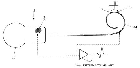
Referring to Figure 1, it is initially noted that the
electrode array including electrodes 12, 13, 14 is used both for
stimulating, and for detecting the evoked response. Detected
data is transmitted via the RF link already provided for
transmitting power and data to the implant 10.
It will be noted that the implant, in addition to the
intra-cochlear electrodes 12-14, preferably includes one or more
extra-cochlear electrodes 31. For the telemetry of evoked
neural potentials, it is greatly preferred to use different
electrodes for delivering the stimulus, and for sensing the
CA 02152049 2001-08-31
4
evoked action potential of the auditory nerve (EAP). Thus, for
monopolar stimulation and measurement, one extra-cochlear
electrode may be used for stimulating, and the other for sensing.
The EAP may according to the present invention be
measured across any two sense electrodes. The waveform on the
sense electrodes consists of the EAP nerve response plus the
stimulus artefact. The stimulus artefact is decaying
exponentially, but can in many cases be orders of magnitude
larger than the nerve response itself. The electrode pair
chosen will optimally detect maximum EAP gradient, and minimum
stimulus artefact. The illustrative sense pair with reference
to figure 1 uses intra-cochlear electrode 14 and extra-cochlear
electrode 31.
Similarly, the stimulus pair 12, 13 may be any selected
electrode pair. The optimal sense pair may vary with the
stimulus pair selected, and may vary from patient to patient, as
would be understood by those skilled in the art. Whilst it is
preferred that the sense electrode pair be distinct from the
stimulating electrode pair, the present invention encompasses
the use of the same electrodes or electrode pair.
The sense pair potential difference is amplified by a
suitable amplifier 20 to produce (ultimately) an EAP measurement
on apparatus external to the patient. The amplified signal is
sampled at 16 intervals and transmitted via the RF link, each
sample being a pair of pulses with a pulse separation
proportional to the amplifier output.
Figure 2 illustrates in block form the internal and
external aspects of the system.
Considering firstly the external system, the overall
arrangement is controlled via digital processor 45, which may be
a personal computer or similar device with suitable interfaces.
Processor 45 drives the transmitter controller 46 and thus the
transmitter stage 43 to send signals via RF link 41 to the
implant 10. Transmitted telemetry data is received via RF link
41 passed through receiver 42 and comparator and
timer/controller stage 44.
Commands are received in the implant 10 via RF link by
receiver coil 30 and pass via receiver stage 32 to
decoder/controller 34, which sends suitable commands to the EAP
CA 02152049 2001-08-31
amplifier/telemetry controller 35 and to switch controller 36.
Switch controller 36 controls the stimulation of selected pairs
of electrodes. The sense electrode signal is amplified by EAP
amplifier/telemetry controller 35 for transmission via
transmitter stage 33 and RF link 30 to the external system 40.
It will be appreciated that any suitable arrangement may
be substituted for the precise arrangement outlined above. The
overall technique for RF communication for powering and
communicating with implanted devices is well known from, for
example, commercially available devices manufactured by Cochlear
Pty Ltd. However, the present invention should not be
considered as limited to this mode of communication - the
invention is independent of the communications mode, and could
if desired be implemented in a directly connected system, for
example. Preferably, the implanted system is integrated into a
single chip as far as possible. Similarly, it will be apparent
that with suitable modifications the present invention is
applicable to other stimulation regimes and sites. The EAP
application is used for the purposes of illustration.
The operation of EAP detection according to the present
invention can best be understood with reference to the timing
diagram of Figure 3. The top line illustrates stimulus via the
stimulus electrode pair: the bottom represents time. In the
preferred embodiment the all electrodes are short circuit prior
to time t2 or stimulation.
At time t2, a stimulus pulse (illustratively a square
biphasic pulse) is applied to stimulus pair 12, 13. Stimulus is
completed at t1 and all electrodes (including the
stimuluselectrodes) are left open circuit. The amplifier
portion 20 of EAP amplifier/telemetry controller 35 is nulled
until time t0. At time t0 (for example), sampled measurements
are taken at times t1, t2 ... until time t16. After t16, the
electrodes are again short circuited, ready for a further cycle
of stimulus and EAP measurement. Note that short circuit before
and after stimulus is one way of ensuring charge balance, but it
is not necessary for recording the nerve response.
Preferably, the time between t2 and t0 is about or
slightly shorter than 400 us, as this is a typical time between
stimulus onset and nerve response occurrence. Of course, this
CA 02152049 2001-08-31
6
may be varied as is appropriate for a given application. The
period between t1 and t0 is preferably programmable such that
the nulling period ends just before the expected EAP occurrence,
thereby minimising the detection of stimulus artefacts. This
programmable delay is controlled by the EAP amplifier/telemetry
controller 35.
Open circuiting all electrodes (including the stimulus
electrodes after stimulation) further reduces the stimulus
artefact and the required dynamic range of the amplifier. This
arrangement has a further advantage in that one of the sense
electrodes can be connected to the common supply rail and a
single ended amplifier can be used. If preferred, a fully
differential input stage could be used instead of the single
ended amplifier.
The sample intervals are typically 100 us, hence the
sampling window is 1.5 to 2.0 ms. Both programmable delay time
and the sampling period can be adjusted over a wide range to
optimise the position and duration of the measurement window.
This also allows recording of nerve responses other than the
auditory response which result from the stimulus.
The measurement sequence is preferably repeated several
times and averaged to further increase the signal to noise ratio
of the measurement. The recorded signal required further post
processing to eliminate the stimulus artefact from the composite
signal. This could involve techniques known in this art such as
masking stimulus and alternate phase sequences.
Figure 4 illustrates a preferred implementation of the
amplifier portion of EAP amplifier/telemetry controller 35
usingfour cascaded single-ended gain stages AMPO, AMP1, AMP2,
AMP3. Illustratively, each stage has a gain of 20dB. Any
suitable amplifier design may be used for individual gain
stages, as would be well understood by those skilled in the
art. All amplifiers are preferably nulled before the recording
period (initial delay) and any offset voltage is stored on the
input capacitors. The length of the nulling period is
programmable and controlled by EAP amplifier/telemetry
controller 35.
At the end of the nulling period (Figure 3,t0) the
amplifier stages are released sequentially, so as to compensate
CA 02152049 2001-08-31
7
for offset voltage due to the charge injection into the previous
stage.
It can be seen from Figure 4 that AMPO and AMPl have a
self-biased DC offset, while AMP2 and AMP3 are biased around
Uref which is approximately half way between the supply rails,
so that the output range is optimised. The last 2 stages have
switchable gain of 20dB or OdB, and as a result the amplifier
may be set for gain of 40,60 or 80dB.
This arrangement allows for accurate measurement of VgAP
without the necessity to separately compensate or adjust for
offsets.
It will be appreciated that variations and additions are
possible within the spirit and scope of the invention.