Sélection de la langue

Search

Sommaire du brevet 2153380 

Énoncé de désistement de responsabilité concernant l'information provenant de tiers

Une partie des informations de ce site Web a été fournie par des sources externes. Le gouvernement du Canada n'assume aucune responsabilité concernant la précision, l'actualité ou la fiabilité des informations fournies par les sources externes. Les utilisateurs qui désirent employer cette information devraient consulter directement la source des informations. Le contenu fourni par les sources externes n'est pas assujetti aux exigences sur les langues officielles, la protection des renseignements personnels et l'accessibilité.

Disponibilité de l'Abrégé et des Revendications

L'apparition de différences dans le texte et l'image des Revendications et de l'Abrégé dépend du moment auquel le document est publié. Les textes des Revendications et de l'Abrégé sont affichés :

  • lorsque la demande peut être examinée par le public;
  • lorsque le brevet est émis (délivrance).
(12) Brevet: (11) CA 2153380
(54) Titre français: DISPOSITIF D'ORIENTATION D'ANTENNE
(54) Titre anglais: ANTENNA POSITIONING APPARATUS
Statut: Réputé périmé
Données bibliographiques
(51) Classification internationale des brevets (CIB):
  • H01Q 1/22 (2006.01)
  • H01Q 1/08 (2006.01)
  • H01Q 1/12 (2006.01)
  • H01Q 1/24 (2006.01)
  • H04B 1/38 (2015.01)
  • H04B 7/185 (2006.01)
  • H04Q 7/32 (2006.01)
(72) Inventeurs :
  • SEITZ, MARTIN VICTOR (Etats-Unis d'Amérique)
(73) Titulaires :
  • MOTOROLA, INC. (Etats-Unis d'Amérique)
(71) Demandeurs :
(74) Agent: GOWLING WLG (CANADA) LLP
(74) Co-agent:
(45) Délivré: 1998-02-24
(22) Date de dépôt: 1995-07-06
(41) Mise à la disponibilité du public: 1996-01-26
Requête d'examen: 1995-07-06
Licence disponible: S.O.
(25) Langue des documents déposés: Anglais

Traité de coopération en matière de brevets (PCT): Non

(30) Données de priorité de la demande:
Numéro de la demande Pays / territoire Date
08/280,094 Etats-Unis d'Amérique 1994-07-25

Abrégés

Abrégé français

Un radiotéléphone utilisé dans un système radiotéléphonique par satellite est doté d'une antenne (12) à gain hémisphérique (14). Comme un satellite (18) peut se trouver n'importe où dans le ciel, le gain d'antenne (14) doit être aligné avec l'hémisphère situé au-dessus de l'utilisateur. Pour ce faire, on utilise un appareil de positionnement d'antenne, comprenant l'antenne (12) ayant une surface de contact en coin (42) fixée à une surface d'attache (36) au moyen d'une goupille (38) et d'une douille (44). La surface d'attache (36) est inclinée par rapport à un plan (24) défini par l'avant (26) du radiotéléphone (10). La combinaison de la surface de contact en coin (42) et de la surface d'attache inclinée (36) positionne l'antenne (12) à un angle ? par rapport au plan de référence (24) lorsque l'antenne est en position active. Par conséquent, l'antenne (12) est orientée à la verticale lors d'un usage normal.


Abrégé anglais


A radiotelephone, used in a satellite radiotelephone system, has an
antenna (12) with a hemispherical gain pattern (14). Since a satellite (18)
can be anywhere in the sky the antenna gain pattern (14) needs to be
aligned with the hemisphere above the user. This is accomplished with
an antenna positioning apparatus, comprising the antenna (12) having a
wedge shaped mating surface (42) affixed to an attaching surface (36) by a
pin (38) and socket (44). The attaching surface (36) slopes downward from
a plane (24) defined by a front face (26) of the radiotelephone (10). The
combination of the wedge shaped mating surface (42) and the downward
sloping attaching surface (36) positions the antenna (12) at an angle ? from
the plane (24) when the antenna is in the active position. As a result the
antenna (12) is vertically oriented when held by the user during normal
use.

Revendications

Note : Les revendications sont présentées dans la langue officielle dans laquelle elles ont été soumises.


- 5 -

Claims

1. An antenna positioning apparatus comprising:
an antenna having a proximal end and a distal end, the antenna
having an elongated tubular shape;
a portable communication device designed to be held in a user's
hand, having an earpiece directed at a front surface, near a top end of the
communication device and a microphone directed at the front surface,
near a bottom end of the communication device;
a pivoting mechanism connecting the proximal end of the antenna
to the communication device, near the top surface, said antenna able to
pivot along a predetermined path from a stored position to at least one
predetermined active position, in which the distal end of the antenna is
above the top end of the communication device and, when the earpiece
and the microphone of the front surface are held by a typical user at a non-
vertical angle near the user's ear and mouth for normal use, a line formed
by the antenna is substantially vertical.

2. The antenna positioning apparatus of claim 1, wherein the active
position includes a position in which the antenna is essentially vertical
when a right handed user holds the communication device so the earpiece
is near the user's ear and the microphone is near the user's mouth.

3. The antenna positioning apparatus of claim 1, wherein the active
position includes a position in which the antenna is essentially vertical
when a left handed user holds the communication device so the earpiece
is near the user's ear and the microphone is near the user's mouth.

4. The antenna positioning apparatus of claim 1, wherein the
antenna has a plurality of predetermined active positions including a
predetermined active position for a right handed user and a
predetermined position for a left handed user.

-6-

5. The antenna positioning apparatus of claim 4,
wherein the antenna continuously pivots along the predetermined
path in a serial succession among the stored position, the predetermined
active position for a right handed user and the predetermined active
position for a left handed user; and
wherein said antenna positioning device includes at least one
detent at one of said predetermined active positions between the stored
position and another of the predetermined active positions.

6. The antenna positioning apparatus of claim 1, wherein the
pivoting mechanism pivots the antenna about an axis inclined at an angle
with respect to the front surface of the portable communication device.

7. The antenna positioning apparatus of claim 1,
wherein said antenna comprises a first pivot portion inclined at a
first angle with respect to a line perpendicular to the elongated tubular
shape of the antenna; and
wherein said pivoting mechanism comprises a second pivot
portion corresponding to the first pivot portion and inclined at a second
angle with respect to a line perpendicular to a surface of the portable
communication device such that at the stored portion the first and second
angles subtract and in the active position the first and second angles add.

8. The antenna positioning apparatus of claim 7, wherein the first
and second angles are the same and cancel each other in the stored
position.

9. The antenna positioning apparatus according to claim 1, wherein
the pivoting mechanism) is able to pivot from a stored position, in which
the distal end of the antenna is near the bottom end of the
communication device, next to one side of the communication device and
substantially parallel to the planes formed by surfaces of the
communication device to the at least one active position.

-7-


10. The antenna positioning apparatus of claim 1, wherein the
communication device is a satellite telephone handset and wherein the
antenna gain pattern is hemispherical.

Description

Note : Les descriptions sont présentées dans la langue officielle dans laquelle elles ont été soumises.

21~338o


ANTENNA POSITIONING APPARATUS

Field of the Invention
This invention relates generally to the field of radiotelephones and
more particularly to an apparatus for positioning an antenna attached to a
radiotelephone .

Background of the Invention

A cellular radiotelephone system consists of a number of base
stations and radiotelephone handsets. The user receives and places
radiotelephone calls through the handset, which is in radio
communication with one of the base stations.
A satellite radio communication system, such as the Iridium
system, has a network of satellites, in a low earth polar orbit, that perform
the same function as the base stations. These satellites transmit and
receive signals from a handset to form a radiotelephone ~y~lelll, allowing
users to place radiotelephone calls from anywhere in the world to
anywhere in the world.
Unlike cellular ~y~l~llls, the satellites do not remain in the same
place with respect to the surface of the earth. Since the satellite could be
anywhere in the hemisphere above the user, the radiotelephone's
antenna needs to have a gain pattern that covers the hemisphere above
the user. Thus, designers have developed an antenna with a
hemispherical gain pattern.
A user wishing to place a radiotelephone call needs to have the
antenna of the radiotelephone oriented to communicate with any of the
possible low earth orbit satellites. As shown in FIG. 5, a radiotelephone
handset 10 has an antenna 12 with a hemispherical gain pattern 14. If a
user 16 tilts the radiotelephone 10 and therefore the antenna 12, the gain
pattern 14 will no longer be aligned with the potential locations of a
satellite 18 in the radiotelephone system.
The prior art antenna positioning systems, shown in FIG. 1, orient
the antenna 12 in the same plane as the body of the radiotelephone 10.

- ` 21~338o

- 2 -

When the user places the radiotelephone's speaker 20 against his ear and
the radiotelephone's microphone 22 up to his mouth the antenna (12)
naturally tilts at an angle 0 with respect to vertical. This is undesirable
because it causes a rotation of the antenna gain pattern 14 which can result
in the radiotelephone not being able to communicate with a satellite 18
near the horizon.
Thus there exists a need for an antenna positioning apparatus that
orients the antenna in a vertical position during normal use.

Brief Description of the Drawings

FIG. 1 is a sketch of a person holding a radiotelephone with a prior
art antenna positioning apparatus;
FIG. 2 is a sketch of a person holding a radiotelephone with an
15 antenna positioning apparatus of this application;
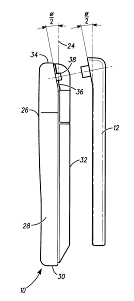
FIG. 3 is an exploded view of a radiotelephone with the antenna
positioning apparatus of this application;
FIG. 4 is a perspective view of the antenna;
FIG. 5 is a sketch showing an antenna gain pattern for the type of
20 antenna used with the antenna positioning apparatus of this application;
and
FIG. 6 is a perspective view of a radiotelephone with antenna
positioning apparatus of this application.

Detailed Description of the Drawings

A solution to the antenna position problem requires an
apparatus that locates the antenna 12 at an angle 0 from a plane 24 defined
by a front face 26 of the radiotelephone 10 (see FIG. 2). For a typical
radiotelephone the angle 0 is around 15 degrees. A mechanism for
positioning the antenna 12 at an angle 0 when in the active position is
shown in FIG. 3. The radiotelephone 10 has the front face 26, two side
sllrfac~ 28, a bottom surface 30, a back surface 32 and a top surface 34. An
attaching surface 36 defines a plane that intersects the plane 24, defined by
the front face 26, at an angle 0/2. A pin 38 is positioned on the attaching
surface 36.

2153380
.
- 3 -

The antenna 12 at a proximal end 39 (see FIG. 4) is attached to an
elbow 40, having a mating surface 42. The mating surface 42 faces the
attaching surface 36 of the radiotelephone 10 when assembled. The
mating surface 42 includes a socket 44 that engages the pin 38 when the
antenna 12 is assembled to the radiotelephone 10. The antenna 12 pivots
about the pin 38. The mating surface is at an angle 0/2 with respect to the
line formed by the antenna 12.
When the antenna 12 is in the stored position a distal end 46 is
pointed towards the bottom surface 30 of the radiotelephone 10 and the
length of the antenna 12 is along the side 28 of the radiotelephone 10. The
antenna 12 is parallel to the plane 24, in the stored position, because the
attaching surface makes a downward sloping angle of 0/2 with the plane
24, while the mating surface 42 of the antenna 12 makes a upward sloping
angle of 0/2. As a result the two angles cancel each other out in the stored
position and the antenna 12 is parallel to the plane 24 when in the stored
position.
From the stored position the antenna 12 is rotated to the active
position in which the distal end 46 of the antenna 12 is above the top
surface 34 of the radiotelephone 10. A further improvement provides
three detent positions 50, 52, 54 when in the active position, as shown in
FIG. 6. A second position 52 corresponds to a 180 degree rotation from the
stored position. While a first position corresponds to a 180 + a degree
rotation and a third position 54 corresponds to a 180 - a degree rotation.
The first position 50 is designed for a right handed user and the angle a
compensates for the angle that the phone tilts back when in use by a right
handed user. While the third position 54 will compensate for the tilt
normally experience by a left handed user.
In a satellite radiotelephone systems it is vital that the antenna gain
pattern cover the hemisphere above the user, to provide optimal service.
A normal user will hold a radiotelephone so that the top of the
radiotelephone points away from the top of his head and towards the back
of his head. Prior art antenna attaching designs will match the orientation
of the antenna to the orientation of the phone. As a result the antenna
will not be in a vertical orientation and the antenna gain pattern will not
cover the hemisphere above the user. The invention of this application
provides a simple, low cost mechanism to orient the antenna in a vertical

2153380
- 4 -

orientation during normal use. Thus providing the user with improved
radiotelephone communication performance.
To those skilled in the art it is obvious that many modifications can
be made to the invention without departing from the spirit of the
5 invention. For instance, a cam device could be used instead of a pivot to
guide the antenna to the desired location, or a universal joint with a
guiding slot could used instead of the pivot and sloping planes. Any such
modification is considered to be part of the inventor's exclusive rights in
this invention. For a full understanding of the scope of the invention
10 re~lel~ce should be made to the appended claims.

Dessin représentatif
Une figure unique qui représente un dessin illustrant l'invention.
États administratifs

Pour une meilleure compréhension de l'état de la demande ou brevet qui figure sur cette page, la rubrique Mise en garde , et les descriptions de Brevet , États administratifs , Taxes périodiques et Historique des paiements devraient être consultées.

États administratifs

Titre Date
Date de délivrance prévu 1998-02-24
(22) Dépôt 1995-07-06
Requête d'examen 1995-07-06
(41) Mise à la disponibilité du public 1996-01-26
(45) Délivré 1998-02-24
Réputé périmé 2002-07-08

Historique d'abandonnement

Il n'y a pas d'historique d'abandonnement

Historique des paiements

Type de taxes Anniversaire Échéance Montant payé Date payée
Le dépôt d'une demande de brevet 0,00 $ 1995-07-06
Enregistrement de documents 0,00 $ 1995-09-21
Taxe de maintien en état - Demande - nouvelle loi 2 1997-07-07 100,00 $ 1997-06-26
Taxe finale 300,00 $ 1997-11-14
Taxe de maintien en état - brevet - nouvelle loi 3 1998-07-06 100,00 $ 1998-06-17
Taxe de maintien en état - brevet - nouvelle loi 4 1999-07-06 100,00 $ 1999-06-16
Taxe de maintien en état - brevet - nouvelle loi 5 2000-07-06 150,00 $ 2000-06-19
Titulaires au dossier

Les titulaires actuels et antérieures au dossier sont affichés en ordre alphabétique.

Titulaires actuels au dossier
MOTOROLA, INC.
Titulaires antérieures au dossier
SEITZ, MARTIN VICTOR
Les propriétaires antérieurs qui ne figurent pas dans la liste des « Propriétaires au dossier » apparaîtront dans d'autres documents au dossier.
Documents

Pour visionner les fichiers sélectionnés, entrer le code reCAPTCHA :


Pour visualiser une image, cliquer sur un lien dans la colonne description du document. Pour télécharger l'image (les images), cliquer l'une ou plusieurs cases à cocher dans la première colonne et ensuite cliquer sur le bouton "Télécharger sélection en format PDF (archive Zip)" ou le bouton "Télécharger sélection (en un fichier PDF fusionné)".

Liste des documents de brevet publiés et non publiés sur la BDBC .

Si vous avez des difficultés à accéder au contenu, veuillez communiquer avec le Centre de services à la clientèle au 1-866-997-1936, ou envoyer un courriel au Centre de service à la clientèle de l'OPIC.


Description du
Document 
Date
(yyyy-mm-dd) 
Nombre de pages   Taille de l'image (Ko) 
Page couverture 1998-02-16 1 53
Page couverture 1996-03-13 1 16
Abrégé 1996-01-26 1 25
Description 1996-01-26 4 169
Dessins 1996-01-26 3 54
Revendications 1996-01-26 3 94
Dessins représentatifs 1998-02-16 1 6
Dessins représentatifs 1998-04-14 1 7
Correspondance 1997-11-14 1 30
Lettre du bureau 1995-07-06 1 26
Lettre du bureau 1995-09-21 1 25