Sélection de la langue

Search

Sommaire du brevet 2155135 

Énoncé de désistement de responsabilité concernant l'information provenant de tiers

Une partie des informations de ce site Web a été fournie par des sources externes. Le gouvernement du Canada n'assume aucune responsabilité concernant la précision, l'actualité ou la fiabilité des informations fournies par les sources externes. Les utilisateurs qui désirent employer cette information devraient consulter directement la source des informations. Le contenu fourni par les sources externes n'est pas assujetti aux exigences sur les langues officielles, la protection des renseignements personnels et l'accessibilité.

Disponibilité de l'Abrégé et des Revendications

L'apparition de différences dans le texte et l'image des Revendications et de l'Abrégé dépend du moment auquel le document est publié. Les textes des Revendications et de l'Abrégé sont affichés :

  • lorsque la demande peut être examinée par le public;
  • lorsque le brevet est émis (délivrance).
(12) Brevet: (11) CA 2155135
(54) Titre français: ANNEAUX DE REFROIDISSEMENT DE PELLICULE DE PLASTIQUE EXTRUDEE
(54) Titre anglais: AIR RINGS FOR COOLING BLOWN PLASTIC FILM
Statut: Périmé
Données bibliographiques
(51) Classification internationale des brevets (CIB):
  • B29C 48/885 (2019.01)
  • B29C 47/88 (2006.01)
(72) Inventeurs :
  • PLANETA, MIREK (Canada)
(73) Titulaires :
  • MACRO ENGINEERING & TECHNOLOGY INC. (Canada)
(71) Demandeurs :
  • PLANETA, MIREK (Canada)
(74) Agent: GOWLING WLG (CANADA) LLP
(74) Co-agent:
(45) Délivré: 2002-02-05
(22) Date de dépôt: 1995-08-01
(41) Mise à la disponibilité du public: 1996-02-12
Requête d'examen: 1998-07-17
Licence disponible: S.O.
(25) Langue des documents déposés: Anglais

Traité de coopération en matière de brevets (PCT): Non

(30) Données de priorité de la demande:
Numéro de la demande Pays / territoire Date
08/289,036 Etats-Unis d'Amérique 1994-08-11

Abrégés

Abrégé français

Anneau de soufflage d'air utilisé pour amener de l'air de refroidissement à un film de plastique tubulaire extrudé une fois que le film a été extrudé par une filière d'extrusion annulaire à température élevée. L'anneau de soufflage d'air possède un élément annulaire inférieur rattachable à une filière d'extrusion annulaire de manière à enceindre le film de plastique tubulaire extrudé tandis que le film sort de la filière d'extrusion, l'élément annulaire inférieur présentant au moins un passage qui le traverse pour amener de l'air de refroidissement depuis l'extérieur vers une partie inférieure du film tubulaire. Un premier élément annulaire supérieur enceint une partie supérieure de l'élément annulaire inférieur dans un rapport radialement espacé entre eux, le premier élément annulaire supérieur faisant saillie au-dessus de l'élément annulaire inférieur et étant fixé de manière détachable à la partie supérieure de l'élément annulaire inférieur par un ensemble d'espacement amovible, qui procure des passages qui s'étendent de manière circonférentielle pour permettre l'écoulement de l'air de refroidissement depuis l'atmosphère ambiante entre l'élément annulaire inférieur et le premier élément annulaire supérieur jusqu'au film tubulaire.


Abrégé anglais

An air ring for supplying cooling air to an extruded tubular plastic film after the film has been extruded from an annular extruder die at an elevated temperature. The air ring has a lower annular member securable to an annular extruder die so as to surround extruded tubular plastic film as the film leaves the extruder die, the lower annular member having at least one passage therethrough for supplying cooling air from the exterior thereof to a lower portion of the tubular film. A first upper annular member surrounds an upper portion of the lower annular member in radially spaced relationship therewith, the first upper annular member projecting above the lower annular member and being detachably secured to the upper portion of the lower annular member by a removable spacer assembly, which provides circumferentially extending passages for the flow of cooling air from the ambient atmosphere between the lower annular member and the first upper annular member to the tubular film.

Revendications

Note : Les revendications sont présentées dans la langue officielle dans laquelle elles ont été soumises.


I CLAIM:
1. An air ring for supplying cooling air to an extruded tubular
plastic film after the film has been extruded from an annular
extruder die at an elevated temperature, said air ring
comprising:
a lower annular member securable to an annular
extruder die so as to surround extruded tubular plastic film as
the film leaves the extruder die, said lower annular member
having at least one passage therethrough for supplying cooling
air from the exterior thereof to a lower portion of the tubular
film, and
a first upper annular member surrounding an upper
portion of the lower annular member in radially spaced
relationship therewith, said first upper annular member
projecting above the lower annular member and being
detachably secured to the upper portion of the lower annular
member by a removable spacer assembly, which provides
circumferentially extending passages for the flow of cooling air
from the ambient atmosphere between the lower annular
member and the first upper annular member to the tubular
film,
said removable spacer assembly comprising a series of


circumferentially spaced securing devices each extending from
the first upper annular member to the lower annular member
and each carrying an annular spacer thereon to maintain said
radially spaced relationship.


2. An air ring according to claim 1 also including a second upper
annular member surrounding an upper portion of the first
upper annular member in radially spaced relationship
therewith, said second upper annular member projecting above
the first upper annular member and being detachably secured
to the upper portion of the first upper annular member by a
further removable spacer assembly, which provides
circumferentially extending passages for the flow of cooling air
from the ambient atmosphere between the first upper annular
member and the second upper annular member to the tubular
film, said further removable spacer assembly comprising a
spacer ring secured to one of the members and a series of
circumferentially spaced securing devices securing the spacer
ring to the other member, each securing device extending from
the other member to the spacer ring and carrying an annular
spacer thereon to maintain radially spaced relationship
between the other member and the spacer ring.


3. An air ring for supplying cooling air to an extruded tubular
plastic film after the film has been extruded from an annular
extruder die at an elevated temperature, said air ring
comprising:
a lower annular member securable to an annular
extruder die so as to surround extruded tubular plastic film as
the film leaves the extruder die, said lower annular member
having at least one passage therethrough for supplying cooling
air from the exterior thereof to a lower portion of the tubular
film, a first upper annular member surrounding an upper
portion of the lower annular member in radially spaced
relationship therewith, said first upper annular member
projecting above the lower annular member and being
detachably secured to the upper portion of the lower annular
member by a removable spacer assembly, which provides
circumferentially extending passages for the flow of cooling air
from the ambient atmosphere between the lower annular
member and the first upper annular member to the tubular
film, and
a second upper annular member surrounding an upper
portion of the first upper annular member in radially spaced
relationship therewith, said second upper annular member


projecting above the first upper annular member and being
detachably secured to the upper portion of the first upper
annular member by a further removable spacer assembly,
which provides circumferentially extending passages for the
flow of cooling air from the ambient atmosphere between the
first upper annular member and the second upper annular
member to the tubular film,
said further removable spacer assembly comprising a
spacer ring secured to one of the members and a series of
circumferentially spaced securing devices securing the spacer
ring to the other member, each securing device extending from
the other member to the spacer ring and carrying an annular
spacer thereon to maintain radially spaced relationship
between the other member and the spacer ring.


Description

Note : Les descriptions sont présentées dans la langue officielle dans laquelle elles ont été soumises.


CA 02155135 2001-05-08
AIR RINGS FOR COOLING BLOWN PLASTIC FILM
This invention relates to air rings for cooling blown plastic
film, that is to say air rings for supplying cooling air to an extruded
tubular plastic film after the film has been extruded from an annular
extruder die at an elevated temperature, i.e. above ambient temperature.
Air rings of this kind are described for example in my prior U.S.
Patent No. 4,826,414 issued May 2, 1989 and my prior U.S. Patent
No. 4,929,162 issued May :29, 1990. Such air rings function in a satisfactory
manner but are somewhat difficult to manufacture and are consequently
expensive.
It is therefore an object of the present invention to provide an
air ring which functions in a satisfactory manner but which is simpler to
manufacture and hence less expensive than previously known air rings.
According to the present invention, an air ring comprises
l:p a lower annular member securable to an annular extruder die so as to
surround extruded tubular plastic film as the film leaves the extruder die,
said lower annular member having at least one passage therethrough for
supplying cooling air from the exterior thereof to a lower portion of the
tubular film, a first upper annular member surrounding an upper portion
of the lower annular member in radially spaced relationship therewith, said
first upper annular member projecting above the lower annular member


2155135
and being detachably secured to the upper portion of the lower annular
member by a removable spacer assembly, which provides circumferentially
extending passages for the flow of cooling air from the ambient
atmosphere between the lower annular member and the first upper annular
member to the tubular film.
The removable spacer assembly may comprise a series of
circumferentially spaced securing devices each carrying an annular spacer
thereon to maintain said radially spaced relationship.
The air ring may also include a second upper annular member
surrounding an upper portion of the first upper annular member in
radially spaced relationship therewith, said second upper annular member
projeting above the first upper annular member and being detachably
secured to the upper portion of the first upper annular member by a
further removable spacer assembly, which provides circumferentially
extending passages for the flow of cooling air from the ambient
atmosphere between the first upper annular member and the second upper
annular member to the tubular film.
The further removable spacer assembly may comprise a spacer
ring secured to one of the members and a series of circumferentially spaced
securing devices securing the spacer ring to the other member, each
securing device carrying an annular spacer.
2


2155135
Brief Decription of the Drawings
One embodiment of the invention will now be described, by
way of example, with reference to the accompanying drawings, of which:
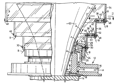
Fig. 1 is a side view, partly in section, of an air ring in
accordance with the invention secured to an annular extruder die, and
Fig. 2 is a horizontal sectional view taken along the line 2-2 of
Fig. 1.
Detailed Description of the Preferred Embodiment
Referring to the drawings, an air ring comprises a lower
annular member 12 secured in known manner to an annular extruder die
14. The lower annular member 12 has passages 16, 18, 20 for supplying
cooling air to a lower portion of the extruded tubular plastic film 22. The
arrangement as so far described is substantially as described and illustrated
in my prior U.S. Patent Nos. 4,826,414 and 4,929,162 previously referred
to, except that the upper portion of the lower annular member 12 is an
auxiliary lower annular member 24 which is screwed on to the lower
portion 26 thereof. The auxiliary lower annular member 24 may
conveniently be made of aluminum.
In accordance with the present invention, and in contrast to
the arrangements described and illustrated in my two prior patents referred
to above, a first upper cylindrical member 28 having a cylindrical
configuration surrounds the auxiliary lower annular member 24 in radially
3


2155135
spaced relationship therewith. The first upper cylindrical member 28
projets above the lower annular member 12 and is detachably secured to
the auxiliary lower annular member 24 by a series of circumferentially
spaced screws 30 which pass through apertures in the lower portion of the
first upper cylindrical member 28 into tapped bores 32 in the auxiliary
lower annular member 24. Annular spacers 34 surround the screws 30
between the first upper cylindrical member 28 and the auxiliary lower
annular member 24 to provide circumferentially extending passages
therebetween. The first upper cylindrical member 28 may conveniently be
made of a suitable transparent material, such as transparent acrylic plastic
material, for example Plexiglass (TM). Typically, there will be from four
to six circumferentially spaced sets of screws 30 and annular spacers 34,
depending on the diameter of the members concerned.
A second transparent upper cylindrical member 36 surrounds
the upper portion of the first upper cylindrical member 28 in spaced
relationship therewith. The second upper cylindrical member 36 projects
above the first upper cylindrical member 28 and is detachably secured
thereto by a spacer assembly 38. The spacer assembly 38 comprises an
aluminum spacer ring 40 detachably secured to the upper portion of the
first upper cylindrical member 28 by screws 42 which pass through
apertures in the first upper cylindrical member 28 into tapped bores 46 in
the radially inner side of the spacer ring 40. The lower end portion of the
4


2155135
second upper cylindrical member 36 is detachably secured to the spacer
ring 40 by circumferentially spaced screws 48 which pass through apertures
in the second upper cylindrical member 36 into tapped bores 50 in the
radially outer side of the spacer ring 40, annular spacers 52 surrounding
screws 48 between the second upper cylindrical member 36 and the spacer
ring 40 to provide circumferentially extending passages between the second
upper cylindrical member 36 and the spacer ring 40. Typically, there will
be four to six circumferentially spaced sets of screws 42, 48 and annular
spacers 52, depending on the diameters of the members concerned.
In this embodiment, a third transparent upper cylindrical
member 54 is also provided and is detachably secured to the second upper
cylindrical member 36 in the same manner as the second upper cylindrical
member 36 is detachably secured to the first upper cylindrical member 28,
i.e. by a spacer assembly 38 comprising spacer ring 40, screws 42, screws 48
and annular spacers 52.
In use, as the tubular plastic film 22 is extruded upwardly
from extruder die 14 as an expanding air-filled bubble, cooling air supplied
to the lower annular member 12 passes through passages 16, 18 and 20 into
contact with and upward movement with the plastic film 22, as indicated
by arrows A, to cool and stabilize the film bubble. Such upward
movement also causes ambient air to pass upwardly, as indicated by arrows
B, through the circumferentially extending passages between the auxiliary
5


2155135
lower annular member 24 and the first upper cylindrical member 28,
between the first upper cylindrical member 28 and the second upper
cylindrical member 36, and between the second upper cylindrical member
36 and the third upper cylindrical member 54, to further cool and stabilize
the film bubble.
It will be readily apparent to a person skilled in the art from
the foregoing description of a preferred embodiment that an air ring in
accordance with the present invention can be more easily adjusted for
different blow-up ratios than previously known air rings. It is a relatively
easy matter to remove existing upper annular members and replace them
with upper annular members of other diameters and different size spacer
assemblies.
In the described embodiment, the presence of transparent
upper annular members enables the portion of the film bubble within the
upper part of the air ring to be easily observed so that any consequent
necessary adjustments to the extruding process can be made promptly.
Other embodiments of the invention will also be clearly
apparent to a person skilled in the art, the scope of the invention being
defined in the appended claims.
6

Dessin représentatif
Une figure unique qui représente un dessin illustrant l'invention.
États administratifs

Pour une meilleure compréhension de l'état de la demande ou brevet qui figure sur cette page, la rubrique Mise en garde , et les descriptions de Brevet , États administratifs , Taxes périodiques et Historique des paiements devraient être consultées.

États administratifs

Titre Date
Date de délivrance prévu 2002-02-05
(22) Dépôt 1995-08-01
(41) Mise à la disponibilité du public 1996-02-12
Requête d'examen 1998-07-17
(45) Délivré 2002-02-05
Expiré 2015-08-03

Historique d'abandonnement

Il n'y a pas d'historique d'abandonnement

Historique des paiements

Type de taxes Anniversaire Échéance Montant payé Date payée
Le dépôt d'une demande de brevet 0,00 $ 1995-08-01
Taxe de maintien en état - Demande - nouvelle loi 2 1997-08-01 100,00 $ 1997-06-16
Requête d'examen 400,00 $ 1998-07-17
Taxe de maintien en état - Demande - nouvelle loi 3 1998-08-03 100,00 $ 1998-07-22
Taxe de maintien en état - Demande - nouvelle loi 4 1999-08-02 100,00 $ 1999-07-08
Taxe de maintien en état - Demande - nouvelle loi 5 2000-08-01 150,00 $ 2000-06-20
Taxe de maintien en état - Demande - nouvelle loi 6 2001-08-01 150,00 $ 2001-07-27
Taxe finale 150,00 $ 2001-11-13
Taxe de maintien en état - brevet - nouvelle loi 7 2002-08-01 150,00 $ 2002-07-24
Taxe de maintien en état - brevet - nouvelle loi 8 2003-08-01 150,00 $ 2003-03-31
Taxe de maintien en état - brevet - nouvelle loi 9 2004-08-02 200,00 $ 2004-07-09
Taxe de maintien en état - brevet - nouvelle loi 10 2005-08-01 250,00 $ 2005-06-30
Taxe de maintien en état - brevet - nouvelle loi 11 2006-08-01 250,00 $ 2006-06-07
Taxe de maintien en état - brevet - nouvelle loi 12 2007-08-01 250,00 $ 2007-05-09
Taxe de maintien en état - brevet - nouvelle loi 13 2008-08-01 250,00 $ 2008-07-24
Taxe de maintien en état - brevet - nouvelle loi 14 2009-08-03 250,00 $ 2009-07-29
Taxe de maintien en état - brevet - nouvelle loi 15 2010-08-02 450,00 $ 2010-05-04
Enregistrement de documents 100,00 $ 2010-10-01
Taxe de maintien en état - brevet - nouvelle loi 16 2011-08-01 450,00 $ 2011-05-09
Taxe de maintien en état - brevet - nouvelle loi 17 2012-08-01 450,00 $ 2012-05-16
Taxe de maintien en état - brevet - nouvelle loi 18 2013-08-01 450,00 $ 2013-07-31
Taxe de maintien en état - brevet - nouvelle loi 19 2014-08-01 450,00 $ 2014-07-31
Titulaires au dossier

Les titulaires actuels et antérieures au dossier sont affichés en ordre alphabétique.

Titulaires actuels au dossier
MACRO ENGINEERING & TECHNOLOGY INC.
Titulaires antérieures au dossier
PLANETA, MIREK
Les propriétaires antérieurs qui ne figurent pas dans la liste des « Propriétaires au dossier » apparaîtront dans d'autres documents au dossier.
Documents

Pour visionner les fichiers sélectionnés, entrer le code reCAPTCHA :


Pour visualiser une image, cliquer sur un lien dans la colonne description du document. Pour télécharger l'image (les images), cliquer l'une ou plusieurs cases à cocher dans la première colonne et ensuite cliquer sur le bouton "Télécharger sélection en format PDF (archive Zip)" ou le bouton "Télécharger sélection (en un fichier PDF fusionné)".

Liste des documents de brevet publiés et non publiés sur la BDBC .

Si vous avez des difficultés à accéder au contenu, veuillez communiquer avec le Centre de services à la clientèle au 1-866-997-1936, ou envoyer un courriel au Centre de service à la clientèle de l'OPIC.


Description du
Document 
Date
(yyyy-mm-dd) 
Nombre de pages   Taille de l'image (Ko) 
Page couverture 1996-04-09 1 15
Abrégé 1996-02-12 1 26
Description 1996-02-12 6 210
Revendications 1996-02-12 4 108
Dessins 1996-02-12 1 40
Description 2001-05-08 6 211
Page couverture 2002-01-07 1 53
Dessins représentatifs 2001-07-13 1 20
Dessins représentatifs 1998-03-04 1 33
Poursuite-Amendment 2002-01-18 2 115
Taxes 2009-07-29 1 33
Taxes 2003-03-31 1 31
Taxes 2002-07-24 1 32
Cession 1995-08-01 4 152
Poursuite-Amendment 1998-07-17 3 117
Poursuite-Amendment 2001-05-08 3 70
Correspondance 2001-11-13 1 34
Poursuite-Amendment 2001-04-25 1 27
Taxes 1997-06-16 1 50
Taxes 2000-06-20 1 39
Taxes 2001-07-27 1 31
Taxes 1999-07-08 1 39
Taxes 1998-07-22 1 48
Taxes 2004-07-09 1 30
Taxes 2005-06-30 1 29
Taxes 2007-05-09 1 31
Taxes 2008-07-24 1 31
Taxes 2010-05-04 1 40
Cession 2010-10-01 4 163
Taxes 2013-07-31 1 33