Sélection de la langue

Search

Sommaire du brevet 2155293 

Énoncé de désistement de responsabilité concernant l'information provenant de tiers

Une partie des informations de ce site Web a été fournie par des sources externes. Le gouvernement du Canada n'assume aucune responsabilité concernant la précision, l'actualité ou la fiabilité des informations fournies par les sources externes. Les utilisateurs qui désirent employer cette information devraient consulter directement la source des informations. Le contenu fourni par les sources externes n'est pas assujetti aux exigences sur les langues officielles, la protection des renseignements personnels et l'accessibilité.

Disponibilité de l'Abrégé et des Revendications

L'apparition de différences dans le texte et l'image des Revendications et de l'Abrégé dépend du moment auquel le document est publié. Les textes des Revendications et de l'Abrégé sont affichés :

  • lorsque la demande peut être examinée par le public;
  • lorsque le brevet est émis (délivrance).
(12) Brevet: (11) CA 2155293
(54) Titre français: GAINE POUR CORPS SOUPLE DE LAMPE DE POCHE
(54) Titre anglais: SLEEVE RETENTION FOR FLEXIBLE CORE OF A FLASHLIGHT
Statut: Périmé
Données bibliographiques
(51) Classification internationale des brevets (CIB):
  • F21V 21/32 (2006.01)
  • F16M 11/40 (2006.01)
  • F21V 21/14 (2006.01)
(72) Inventeurs :
  • ROUSSO, JOHN G. (Etats-Unis d'Amérique)
  • HOLBROOK, PAUL R. (Etats-Unis d'Amérique)
(73) Titulaires :
  • BLACK & DECKER INC. (Etats-Unis d'Amérique)
(71) Demandeurs :
(74) Agent: GOWLING LAFLEUR HENDERSON LLP
(74) Co-agent:
(45) Délivré: 1997-01-21
(22) Date de dépôt: 1995-08-02
(41) Mise à la disponibilité du public: 1995-10-06
Requête d'examen: 1995-09-06
Licence disponible: S.O.
(25) Langue des documents déposés: Anglais

Traité de coopération en matière de brevets (PCT): Non

(30) Données de priorité de la demande:
Numéro de la demande Pays / territoire Date
08/286,852 Etats-Unis d'Amérique 1994-08-05

Abrégés

Abrégé français

Lampe de poche comprenant un noyau flexible muni de deux fils conducteurs qui raccordent de manière électrique une source d'énergie à un élément utilisant de l'énergie. Une colonne flexible entoure les deux fils conducteurs et comprend une série d'éléments interconnectés et rotatifs dans tous les plans. Un manchon élastique enveloppe la surface extérieure des éléments rotatifs formant la colonne. La lampe de poche comporte un logement d'extrémité de travail et un logement de base. Un premier dispositif d'ancrage raccorde une extrémité du noyau flexible au compartiment de base et un deuxième dispositif d'ancrage raccorde l'autre extrémité du noyau flexible au compartiment de travail. On empêche la surface extérieure du manchon élastique de se déplacer longitudinalement ou de s'entortiller par rapport à chaque compartiment.


Abrégé anglais


A flashlight includes a flexible core
comprising a pair of conductive wires which
electrically connect a source of power to a power
using implement. A flexible spine surrounds the
pair of conductive wires and includes a plurality
of interconnected universally rotatable members.
A resilient sleeve engages the outer surface of
the rotatable members forming the spine. The
flashlight includes a working end housing and a
base housing. A first anchor connects one end of
the flexible core to the base end housing and a
second anchor connects the other end of the
flexible core to the working end housing. The
outer surface of the resilient sleeve is
restrained against relative twisting or
longitudinal movement with respect to each
housing.

Revendications

Note : Les revendications sont présentées dans la langue officielle dans laquelle elles ont été soumises.


-16-
WHAT IS CLAIMED IS:
1. A flashlight comprising:
a base housing forming a power end for
said flashlight and having a longitudinally
extending bore including at least one battery
housed therein;
a working end housing spaced from said
base housing and supporting a reflector, a lens,
and a light bulb, said working end housing
including means defining a longitudinally
extending bore;
a flexible core assembly connecting
said base housing to said working end housing and
comprising a pair of conductive wires electrically
connecting said battery to said light bulb, a
flexible spine surrounding said pair of conductive
wires and including a plurality of interconnected
and universally rotatable members, and a resilient
sleeve member engaging an outer surface of each of
the rotatable members forming said spine;
a first anchor connected to a first end of
said flexible core and having a portion extending
within the bore of said base housing, said anchor
including first gripping means underlying the
resilient sleeve member of said flexible core, and
said base housing bore including second gripping


-17-
means overlying the sleeve of said flexible core
and sandwiching said sleeve between said first and
second gripping means; and
a second anchor connected to a second end of
said flexible core and having a portion extending
within the bore of said working end housing, said
second anchor including third gripping means
underlying the sleeve of said flexible core and
said working end housing bore including fourth
gripping means overlying the sleeve of said
flexible core and sandwiching said sleeve between
said third and fourth gripping means.
2. A flashlight in accordance with Claim 1
wherein said first and third gripping means
comprise a radially extending rib.
3. A flashlight in accordance with Claim 1
wherein each of said anchors has first locking
means and each of the bores of said working end
housing and said base housing includes second
locking means for engaging said first locking
means to maintain the flexible core in a fixed
circumferential position relative to the bores of
said base and working end housings.
4. A flashlight in accordance with Claim 3
wherein a selected one of said first and second
locking means comprises a longitudinally extending


-18-
rib and the other of said locking means comprises
a complementary concave surface for receiving said
rib.
5. A flashlight in accordance with Claim 4
wherein a selected one of said third and fourth
locking means comprises a longitudinally extending
rib and the other of said third and fourth locking
means comprises a complementary concave surface
for receiving said rib.
6. A flashlight comprising:
a base housing forming a power end for
said flashlight and having a longitudinally
extending bore including at least one battery
housed therein;
a working end housing spaced from said
base housing and supporting a reflector, a lens,
and a light bulb, said working end housing
including means defining a longitudinally
extending bore;
a flexible core assembly connecting
said base housing to said working end housing and
comprising a pair of conductive wires electrically
connecting said battery to said light bulb, a
flexible spine surrounding said pair of conductive
wires and including a plurality of interconnected
and universally rotatable members, and a resilient


-19-
sleeve member engaging an outer surface of each of
the rotatable members forming said spine, said
sleeve member including a first end extending into
the bore of the base housing and a second end
extending into the bore of the working end
housing, each of said bores includes a plurality
of inwardly extending ridges for engaging the
outer surface of said sleeve.

7. A flashlight in accordance with claim 6
wherein the ridges have a shark tooth-like shape
in vertical cross-section.


-20-
8. A flashlight comprising:
a base housing forming a power end for said
flashlight and having a longitudinally extending bore;
a working end housing spaced from said base housing
and including means defining a longitudinally extending
bore;
a flexible core assembly connecting said base housing
to said working end housing and comprising a pair of
conductive wires electrically connecting said base housing
to said working end housing, a flexible spine surrounding
said pair of conductive wires and including a plurality of
interconnected and universally rotatable members, and a
resilient sleeve member surrounding an outer surface of
each of the rotatable members forming said spine;
a first anchor connected to a first end of said
flexible core and having a portion extending within the
bore of said base housing, said anchor including first
gripping means underlying the resilient sleeve member of
said flexible core, and said base housing including second
gripping means overlying the sleeve of said flexible core
and sandwiching said sleeve between said first and second
gripping means; and
a second anchor connected to a second end of said
flexible core and having a portion extending within the
bore of said working end housing, said second anchor
including third gripping means underlying the sleeve of
said flexible core and said working end housing bore
including fourth gripping means overlying the sleeve of
said flexible core and sandwiching said sleeve between
said third and fourth gripping means.

9. A flashlight in accordance with claim 8 wherein said
first and third gripping means comprise a radially
extending rib.

10. A flashlight in accordance with claim 9 wherein each
of said anchors has first locking means and each of the
bores of said working end housing and said base housing
include second locking means for engaging said first

-21-
locking means to maintain the flexible core in a fixed
circumferential position relative to the bores of said
base and working end housings.

11. A flashlight in accordance with claim 10 wherein a
selected one of said first and second locking means
comprises a longitudinally extending rib and the other of
said locking means comprises a complementary concave
surface for receiving said rib.

12. A flashlight in accordance with claim 11 wherein a
selected one of said third and fourth locking means
comprises a longitudinally extending rib and the other of
said third and fourth locking means comprises a
complementary concave surface for receiving said rib.

13. A flashlight comprising:
a base housing forming a power end for said
flashlight and having means defining a longitudinally
extending first bore;
a working end housing spaced from said base housing
and including means defining a longitudinally extending
second bore;
a flexible core assembly connecting said base housing
to said working end housing and comprising a pair of
conductive wires electrically connecting said base housing
to said working end housing, a flexible spine including a
plurality of interconnected and universally rotatable
members, and a resilient sleeve member surrounding an
outer surface of the rotatable members forming said spine,
and
a first anchor connected to a first end of said
flexible core assembly and having a portion extending
within a selected one of the bores of said base housing
and said working end housing, said anchor including first
gripping means underlying the resilient sleeve member of
said flexible core assembly and said means defining said


-22-
selected one bore including second gripping means
overlaying the sleeve of said flexible core assembly and
sandwiching said sleeve between said first and second
gripping means.

14. A flashlight in accordance with claim 13 wherein said
selected one bore is the bore of said base housing.

15. A flashlight in accordance with claim 13 wherein said
selected one bore is the bore of said working end housing.

16. A flashlight in accordance with claim 13 further
including a second anchor connected to a second end of
said flexible core assembly and having a portion extending
within the other of said bores, said second anchor
including third gripping means underlying the sleeve of
said flexible core assembly and said means defining the
other of said bores including fourth gripping means
overlying the sleeve of said flexible core assembly and
sandwiching said sleeve between said third and fourth
gripping means.

17. A flashlight in accordance with claim 16 wherein said
first and third gripping means comprise radially extending
ribs.

18. A flashlight in accordance with claim 16 wherein each
of said anchors has first locking means and each of the
means defining said bores include second locking means for
engaging said first locking means to maintain the flexible
core assembly in a fixed circumferential position relative
to the bores of said base and working end housings.

19. A flashlight in accordance with claim 17 wherein a
selected one of said first and second locking means
comprises a longitudinally extending rib and the other of
said locking means comprises a complementary concave

-23-
surface for receiving said ribs.

20. A flashlight in accordance with claim 13 wherein said
first anchor has first locking means and said selected one
bore includes second locking means for engaging said first
locking means to maintain the flexible core in a fixed
circumferential position relative to said bore.

21. A flashlight in accordance with claim 20 wherein a
selected one of said first and second locking means
comprises a longitudinally extending rib and the other of
said locking means comprises a complementary concave
surface for receiving said rib.

22. A flashlight comprising:
a first end functioning as a tail for the flashlight;
a second end including a housing having a bulb
holder, a reflector and a lens mounted therewithin and
spaced from said first end, said housing including means
defining a longitudinally extending bore;
a flexible core assembly connecting said first and
second end of said flashlight and comprising a flexible
spine including a plurality of interconnected and
universally rotatable members, and a resilient sleeve
member surrounding an outer surface of the rotatable
members forming said spine; and
a first anchor connected to a first end of said
flexible core assembly and having a portion extending
within said bore of said housing, said anchor and said
housing bore including interengaging means for retaining
said flexible core assembly within said bore.

23. A flashlight in accordance with claim 22 wherein said
anchor and said means defining said bore sandwich said
resilient sleeve therebetween for preventing
circumferential movement of said sleeve relative to said
bore.


-24-
24. A flashlight comprising:
a first end functioning as a tail for the flashlight;
a second end including a housing having a bulb, a
reflector and a lens mounted therewithin and spaced from
said first end, said housing including means defining a
longitudinally extending bore;
a flexible core assembly connecting said first and
second end of said flashlight and comprising a flexible
spine including a plurality of interconnected and
universally rotatable members, and a resilient sleeve
member surrounding an outer surface of the rotatable
members forming said spine; and
a first end anchor connected to a first end of said
flexible core assembly and having a portion extending
within said bore of said housing, said anchor and said
means defining said bore sandwiching said resilient sleeve
therebetween for preventing circumferential movement of
said sleeve relative to said bore.

25. A flashlight in accordance with claim 24 wherein said
first end functions as a counterweight and the second end
is capable of being oriented in a plurality of independent
self-supporting positions.

Description

Note : Les descriptions sont présentées dans la langue officielle dans laquelle elles ont été soumises.


- -- 2 1 55~93


SLE~v~ K~l~NllON FOR FTT~TRTT~ CORE
OF A FT~s~T.TGHT


BACKGROUND OF THE INVENTION


This invention relates to a hand-held
flashlight and in particular to such a flashlight
having a flexible core which may be pulled or
twisted relative to a power end housing and/or a
working end housing.

In co-pending Canadian Patent
Application Serial No. 2,155,291 filed
concurrently herewith in the names of Lee Eckert,
Robert Kubicko and Julian Watt entitled
"Flashlight With Flexible Core" and assigned to
the same assignee as the assignee hereof, there is
disclosed a flashlight with a flexible core. In
the flashlight, a pair of conductive wires
electrically connect a source of power to a power
using implement. A flexible spine surrounds a
pair of conductive wires and includes a plurality
of interconnected universally rotatable members.
A resilient sleeve engages the outer surface of
the rotatable members forming the spine. Each
end of the spine is connected to a corresponding
anchor. One anchor connects one end of the spine


- 215529~

--2--
to the power end housing and a second anchor
connects the other end of the spine to the working
end housing of the flashlight.
Each of the anchors fits within a
corresponding bore formed in each of the two
housings of the flashlight. The opposite ends of
the resilient sleeve fit over the outer surface of
a corresponding anchor and are thus sandwiched
between the inner surface of the bore of one of
the housings and the outer surface of the anchor
held within the bore.
The flexible spine of the flashlight enables
the flashlight to be bent, coiled or draped into
various positions. Both the torsional and pulling
forces applied to the flexible spine and to the
resilient sleeve as a consequence of the bending,
coiling or draping of the flexible core into
various positions have a tendency to separate the
core from the flashlight housings.
Accordingly it is an object of this invention
to prevent the resilient sleeve of a flashlight
having a flexible core from being separated from
the housing sections of the flashlight either
through torsional or axial forces and to prevent
damage to the flexible spine and internal
conductors due to excessive torsional action.


215S29~


-3-
SUMMARY OF THE INVENTION
The foregoing object and other objects of
this invention are attained in a flashlight
including a base housing forming a power end for
the flashlight and having a longitudinally
extending bore having at least one battery housed
therein. A working end housing is spaced from the
base and supports a reflector, a lens and a light
bulb. The working end housing includes means
defining a longitudinally extending bore. A
flexible core assembly connects the base housing
to the working end housing and includes a pair of
conductive wires electrically connecting the
battery to the light bulb, a flexible spine
surrounding the pair of conductive wires and
including a plurality of interconnected and
universally rotatable members, and a resilient
sleeve member engaging an outer surface of each of
the rotatable members forming the spine. A first
anchor is connected to a first end of the flexible
core and has a portion extending within the bore
of the base housing. The first anchor includes
first gripping means underlying the sleeve of the
flexible core and the base housing bore includes
second gripping means overlying the sleeve of the


`- 21~S%93


flexible core sandwiching the sleeve between the
first and second gripping means. A second anchor
is connected to a second end of the flexible core
and has a portion extending within the bore of the
working end housing. The second anchor includes
third gripping means underlying the sleeve of the
flexible core and said working end housing bore
includes fourth gripping means overlying the
sleeve of the flexible core to sandwich the sleeve
between said third and fourth gripping means.


BRIEF DESCRIPTION OF THE DRAWING


Figure 1 is a perspective, exploded view
illustrating features of the flashlight of the
invention;


Figure 2 is a side elevational view,
partially in section, of the flashlight of Figure
l;


Figure 3 is a side elevational view with
portions broken away to illustrate further details
of the flashlight;


21~5293


Figure 4 is an enlarged elevational view
illustrating details of a portion of the
flashlight of the pre~ent invention;


Figure 5 is an enlarged elevational view of
a further portion of the flashlight of the
invention;


Figure 6 is a perspective view of the
flashlight in a somewhat folded position
illustrating the manner in which the two housings
of the flashlight may be joined together;


Figure 7 is a perspective exploded view of a
portion of the flashlight;


Figure 8 is a view similar to Figure 7
showing the parts in their assembled state;


Figure 9 is an exploded perspective view of
a further portion of the flashlight;


Figure 10 is an exploded perspective view of
a subassembly of the flashlight;


21~S293


Figure 11 is an enlarged sectional view taken
along line 11-11 of Figure 12;


Figure 12 is a fragmentary sectional view of
a portion of one of the housings of the flashlight
illustrating details thereof;


Figure 13 is an enlarged sectional view taken
along line 13-13 of Figure 12; and


Figure 14 is an end view taken along line
14-14 of Figure 1.


DESCRIPTION OF THE PREFERRED EMBODIMENT


Referring now to the various figures of the
drawing, there is disclosed a preferred embodiment
of the present invention. In referring to the
various figures of the drawing, like numerals

shall refer to like parts.
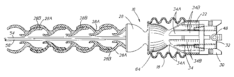
Referring specifically to Figure 1, there is
disclosed a flashlight 10 having a first housing
12 and a second housing 14. Housings 12 and 14
are spaced apart and are connected together
through a flexible core 16. Housing 12 serves as


215S293


--7--
the power end of the flashlight and contains
therewithin batteries 78 and 80 (see Figure 2)
used as the primary source of electrical power for
the flashlight. Batteries 78 and 80 may be
standard C-cells.
Housing 14 functions as the working end of
flashlight 10 and includes a lens 50. As shown in
Figure 2, housing 14 also has mounted therewithin
reflector 90 and bulb 92. A switch 20 is provided
to selectively connect bulb 92 to the source of
electrical power such as batteries 78 and 80.
Housing 14 is generally L-shaped and includes
a generally cylindrically-shaped elongated leg 25
and a somewhat rectangularly-shaped shorter leg 24
extending from leg 25. Leg 24 mounts lens 50,
reflector 90, and bulb 92.
Housing 12 includes a bore 13 and leg 25 of
housing 14 includes a similar bore 15. One end of
flexible core 16 is inserted into bore 15 and the
other end is inserted into bore 13. Each end of
core 16 has an anchor 22 to be more fully
described hereinafter which is inserted into one
of the bores 13, 15 for joining flexible core 18
to housings 12 and 14.
Referring primarily to Figures 2-10,

2 1 5 ~ 2 9 3


additional features of flashlight 10 shall now be
described in detail. Flexible core 16 includes an
outer resilient sleeve 18 made from a resilient
elastomeric material such as a thermoplastic
rubber sold by the Monsanto Corporation under the
trademark "Santoprene." Referring particularly to
Figure 4 a flexible spine 28 is contained within
sleeve 18. Spine 28 comprises a plurality of
interconnected universally rotatable members.
Each universally rotatable member comprises a male
end portion 28A and a female end portion 28B. The
male end portion 28A has an outer surface
comprising a frustum of a sphere and the female
end portion 28B has a mating inner surface
comprising a frustum of a sphere which is
dimensioned so that, when the male end portion 28A
is inserted into the female end portion 28B, there
is frictional contact between the mating outer and
inner surfaces 28A and 28B. These frictional
forces function as retaining means to hold one
member of the flexible spine 28 at any desired
location relative to an interconnected member.
These frictional forces may be overcome which
permits interconnected members to be moved
relative to each other so that their longitudinal


2155293


axes may either be in or out of alignment. The
interconnected segments have relatively
unrestricted rotational movement therebetween.
The segments of the flexible spine 28 are produced
by Lockwood Products, Inc. and are made from
acetal plastic or other suitable material.
Electrical conductors 54 and 56 are disposed
within flexible spine 28. One end of conductors
54, 56 is connected to housing 12 and the other
end of the conductors is connected to working end
housing 14.
Sleeve 18 provides a protective cover over
spine 28. The sleeve maintains an attractive
appearance of the flashlight even when the
individual members of spine 28 are skewed relative
to each other.
An anchor 22 is connected to each end of
flexible core 16. One of the anchors is inserted
into bore 13 of housing 12 and the other of the
anchors is inserted into bore 15 of housing 14.
Anchor 22 includes a ball portion 64, a main body
portion 66 which includes a plurality of
upstanding ribs 34 and a somewhat rectangularly
shaped portion 30. The height of center rib 34A is
somewhat greater when compared to the height of


21~5293


--10--
the other ribs 34 of each anchor 22. As will be
more fully described hereinafter, portion 30 has
an open end facing away from body portion 66 for
receiving strain relief 32 therewithin. Each rib
34 includes a ramp-like leading surface 34B for
expanding the material of sleeve 18 outwardly to
enable each end of the sleeve to be emplaced about
an anchor.
Strain relief 32 includes a pair of
longitudinally spaced slots 47. Strain relief 32
mounted within housing 14 receives contacts 36, 38
in slots 47 while strain relief 32 mounted in
housing 12 receives contacts 42, 46 in slots 47.
The strain relief electrically connects conductors
54,56 to the contacts in each housing 12, 14.
Contact 42 in housing 12 is, in turn, connected to
negative strip conductor 45 while contact 42 is
connected to positive conductor 44. (See Figure 3)
Conductors 44 and 45 are, in turn, connected to
batteries 78 and 80. Housing 12 includes a
removable battery cap 40. Contacts 36, 38 are
connected to conductors 58, 60 in housing 14.
As shown, switch 20 is in series with
conductor 58. As is known to those skilled in the
art, switch 20 is normally open and is closed to


215~29i3


--ll--
connect bulb 92 to batteries 78, 80 via the
various electrical conductors and contacts noted
previously.
Referring specifically to Figures 1 and 6,
one of the housings, for example housing 12
includes an upstanding rib 26. Rib 26 includes a
relatively thin elongated portion 27 connected to
a relatively wide elongated portion 29. The other
of the housings, for example housing 14 includes a
groove 68 whose length is generally coextensive
with the length of upstanding rib 26. Groove 68
is generally U-shaped and includes a pair of
spring clips 52. Spring clips 52 are placed within
groove 68 in a portion which overlies relatively
narrow portion 27 of rib 26. If it is desired to
reduce the overall length of flashlight 10, for
example, for storage purposes, or for holding the
flashlight for use in a conventional hand-held
manner, core 16 is folded so that the core forms a
generally U-shape so that housing 12 lies in the
same vertical plane as housing 14. As shown
specifically in Figure 6, when core 16 is folded
as described, rib 26 underlies U-shaped groove 68.
To join the two housings together, rib 26 is
snapped into groove 68. Relatively narrow portion


21~29~

-12-
27 of rib 26 is inserted between the opposed faces
of spring clips 52 which forces the opposed faces
outwardly. When the rib is inserted into the
groove, the opposed faces of the spring clip are
forced inwardly to lock the rib within groove 68
to positively join the two housings together.
As described previously, each end of flexible
core 16 includes an anchor 22. One of the anchors
is inserted into bore 13 and the other of the
anchors is inserted into bore 15. During testing,
it has been found that twisting or turning the
flexible core to obtain a desired configuration
for the flashlight produces forces which tend to
pull the sleeve from either or both bores of the
housings or twist either end of sleeve 18 relative
to bores 13 or 15. To prevent the undesired
occurrence of the separation of sleeve 18 from one
or both housings and the undesired twisting of
sleeve 18 relative to the housings, grasping
means, to be more fully described hereinafter,
have been added to both bores 13, 15 and anchors
22.
Referring specifically to Figures 11-14, each
bore 13, 15 is provided with a plurality of
circumferentially spaced inwardly extending ridges


21552g3

-13-
respectively 100 and 102. Ridges 100 and 102
extend radially inwardly towards the surface of
sleeve 18. In addition, each bore includes a pair
of 180 degree circumferentially spaced grooves 104
which underly ribs 34A when each anchor 22 is
placed in a respective bore 13, 15.
Housing 14 includes four circumferentially
spaced ridges 100 whereas housing 12 includes 12
circumferentially spaced ridges 102. The length
of each ridge 100 is greater than the length of
each ridge 102. As shown in Figure 13, the
cross-sectional shape of each ridge 100 (or 102)
is similar to a shark's tooth so that the outer
surface of the sleeve engaged by each ridge 100,
102 is firmly grasped to sandwich the sleeve
between the outer surface of anchor 22 and the
outer surface of each ridge. This arrangement
prevents the sleeve from being twisted relative to
each bore 13, 15 and prevents the sleeve from
being separated from one or the other of housings
12, 14.
To further prevent any undesired twisting or
longitudinal movement of the sleeve, ribs 34A act
to force the resilient material of sleeve 18 into
the underlying grooves 104. The combination of


21~529~


-14-
ribs 34A and grooves 104 further prevent twisting
of sleeve 18.
A further feature of the flashlight relates
to strain relief 32. Strain relief 32 includes a
hub portion 48 having a relatively enlarged boss
48A formed at one end of the hub. The other end
of the hub does not have an enlarged boss similar
to boss 48A and the end of the hub lies in the
same vertical plane relative to the vertical plane
of the end face of body portion 30 of anchor 22.
Each housing 12, 14, includes a relatively
large inwardly extending boss 69 and a second
circumferentially spaced relatively smaller boss
69A. When each anchor 22 and its associated strain
relief 32 is inserted into one of the bores 13,
15, enlarged boss 48A of strain relief 32 is
aligned with relatively smaller boss 69A of the
housing and the flat surface 48B of the hub is
aligned with relatively large boss 69 of the
housing. In effect, the strain relief can only be
inserted within the bore in one position due to
the relationships established by bosses 48A, 69A
and 69B and the flat surface 48B of hub 48. The
foregoing enables anchor 22 and strain relief 32
to be used with a polarized plug. A screw 67 or


21~5293


-15-
similar means is inserted through boss 69, hub 48
and boss 69A to affix each anchor 22 to its
respective housing.
While a preferred embodiment of the present
invention has been described and illustrated, the
invention should not be limited thereto but may be
otherwise embodied within the scope of the
following claims.


Dessin représentatif
Une figure unique qui représente un dessin illustrant l'invention.
États administratifs

Pour une meilleure compréhension de l'état de la demande ou brevet qui figure sur cette page, la rubrique Mise en garde , et les descriptions de Brevet , États administratifs , Taxes périodiques et Historique des paiements devraient être consultées.

États administratifs

Titre Date
Date de délivrance prévu 1997-01-21
(22) Dépôt 1995-08-02
Requête d'examen 1995-09-06
(41) Mise à la disponibilité du public 1995-10-06
(45) Délivré 1997-01-21
Expiré 2015-08-03

Historique d'abandonnement

Il n'y a pas d'historique d'abandonnement

Historique des paiements

Type de taxes Anniversaire Échéance Montant payé Date payée
Le dépôt d'une demande de brevet 0,00 $ 1995-08-02
Enregistrement de documents 0,00 $ 1995-11-02
Taxe de maintien en état - brevet - nouvelle loi 2 1997-08-04 100,00 $ 1997-07-16
Taxe de maintien en état - brevet - nouvelle loi 3 1998-08-03 100,00 $ 1998-07-15
Taxe de maintien en état - brevet - nouvelle loi 4 1999-08-02 100,00 $ 1999-07-20
Taxe de maintien en état - brevet - nouvelle loi 5 2000-08-02 150,00 $ 2000-07-20
Taxe de maintien en état - brevet - nouvelle loi 6 2001-08-02 150,00 $ 2001-07-19
Taxe de maintien en état - brevet - nouvelle loi 7 2002-08-02 150,00 $ 2002-07-18
Taxe de maintien en état - brevet - nouvelle loi 8 2003-08-04 150,00 $ 2003-07-21
Taxe de maintien en état - brevet - nouvelle loi 9 2004-08-02 200,00 $ 2004-07-21
Taxe de maintien en état - brevet - nouvelle loi 10 2005-08-02 250,00 $ 2005-07-20
Taxe de maintien en état - brevet - nouvelle loi 11 2006-08-02 250,00 $ 2006-07-17
Taxe de maintien en état - brevet - nouvelle loi 12 2007-08-02 250,00 $ 2007-07-25
Taxe de maintien en état - brevet - nouvelle loi 13 2008-08-04 250,00 $ 2008-07-17
Taxe de maintien en état - brevet - nouvelle loi 14 2009-08-03 250,00 $ 2009-07-21
Taxe de maintien en état - brevet - nouvelle loi 15 2010-08-02 450,00 $ 2010-07-19
Taxe de maintien en état - brevet - nouvelle loi 16 2011-08-02 450,00 $ 2011-07-18
Taxe de maintien en état - brevet - nouvelle loi 17 2012-08-02 450,00 $ 2012-07-17
Taxe de maintien en état - brevet - nouvelle loi 18 2013-08-02 450,00 $ 2013-07-17
Taxe de maintien en état - brevet - nouvelle loi 19 2014-08-04 450,00 $ 2014-07-29
Titulaires au dossier

Les titulaires actuels et antérieures au dossier sont affichés en ordre alphabétique.

Titulaires actuels au dossier
BLACK & DECKER INC.
Titulaires antérieures au dossier
HOLBROOK, PAUL R.
ROUSSO, JOHN G.
Les propriétaires antérieurs qui ne figurent pas dans la liste des « Propriétaires au dossier » apparaîtront dans d'autres documents au dossier.
Documents

Pour visionner les fichiers sélectionnés, entrer le code reCAPTCHA :


Pour visualiser une image, cliquer sur un lien dans la colonne description du document. Pour télécharger l'image (les images), cliquer l'une ou plusieurs cases à cocher dans la première colonne et ensuite cliquer sur le bouton "Télécharger sélection en format PDF (archive Zip)" ou le bouton "Télécharger sélection (en un fichier PDF fusionné)".

Liste des documents de brevet publiés et non publiés sur la BDBC .

Si vous avez des difficultés à accéder au contenu, veuillez communiquer avec le Centre de services à la clientèle au 1-866-997-1936, ou envoyer un courriel au Centre de service à la clientèle de l'OPIC.


Description du
Document 
Date
(yyyy-mm-dd) 
Nombre de pages   Taille de l'image (Ko) 
Abrégé 1997-01-21 1 23
Page couverture 1997-01-21 1 15
Page couverture 1998-08-12 1 15
Description 1997-01-21 15 409
Revendications 1997-01-21 9 316
Dessins 1997-01-21 8 270
Page couverture 1995-12-16 1 30
Abrégé 1995-12-16 1 44
Revendications 1995-12-16 4 157
Dessins 1995-12-16 8 371
Description 1995-12-16 15 639
Dessins représentatifs 1999-07-14 1 23
Correspondance de la poursuite 1995-08-02 6 246
Lettre du bureau 1995-09-25 1 26
Demande d'examen 1995-09-25 2 68
Correspondance de la poursuite 1996-05-07 2 68
Correspondance de la poursuite 1996-05-07 11 532
Demande d'examen 1996-08-20 2 69
Correspondance de la poursuite 1996-09-24 3 127
Correspondance reliée aux formalités 1996-11-15 1 34
Lettre du bureau 1996-03-04 1 33
Correspondance de la poursuite 1995-10-19 2 81
Lettre du bureau 1996-03-04 1 39
Correspondance de la poursuite 1995-09-06 1 43
Correspondance reliée aux formalités 1995-09-06 1 30