Note : Les descriptions sont présentées dans la langue officielle dans laquelle elles ont été soumises.
2157534
i Title: CENTRAL VACUUM INLET MOUNTING PLATE
WITH REMOVABLE PROTECTOR
FIELD OF THE INVENTION
This invention relates generally to the field of central vacuum systems in
which a central
vacuum source is connected by conduits to various valves located inside a
dwelling or other
6 building. In particular this invention relates to a component used in the
valve assemblies
through which portable suction hoses may be attached to the central vacuum
system.
BACKGROUND OF THE INVENTION
In central vacuum systems there are two main types of components, namely built
in
components and portable components. The built in components consist of the
central vacuum
11 motor which is typically installed in a basement or garage of a dwelling,
and plastic conduits
which run under floors and inside walls and are connected to the vacuum motor.
The
conduits are typically provided with wall mounted inlet valves. The portable
components
typically comprise a hose, having a wand at the end, which in turn has a head.
Passive and
active heads are used with active heads such as beater bars being more popular
for carpeted
16 surfaces.
In such central vacuum systems the portable components are connected to the
built in
components at fittings commonly referred to as inlet valves. The valves are
usually mounted
in walls and are provided with a hinged cover which seals a vacuum opening. A
hose cuff is
provided on the hose which mates with and seals with the vacuum opening in the
valve,
21 which becomes exposed when the hinged cover is lifted.
Most usually the valve is comprised of a number of different elements which
are attached
together to form an assembly. In the past there have been many different types
of inlet valve
assemblies for the purpose of providing a convenient hose attachment for
central vacuum
systems. Such assemblies usually comprise a backing or mounting plate, which
is attached
26 to a wall stud or the like and a cover plate or valve which is inserted
into the backing or
mounting plate and which carries the hinged cover for the vacuum opening. The
vacuum
conduit is usually attached to the back of the backing plate and wires may be
run along side
the conduit to pass through the backing plate and to connect to switches or
contacts for
2157534
-3-
1 engaging the vacuum motor. Thus when the hose cuff of the portable hose is
inserted into the
vacuum opening, a low voltage circuit is closed and the vacuum motor is
engaged. An
example of this type of fitting is shown in U.S patent 4,336,427 to Lindsay.
Typically, a rubber seal or gasket is provided between the cover plate and the
backing plate to
ensure a good vacuum tight seal. When the rubber gasket or seal is mounted
inside of the
6 vacuum opening in the backing plate, it becomes partially exposed and thus
is susceptible to
damage during installation of the drywall over or around the fitting.
Typically in new house
installations, the backing plate will be mounted onto the end of the conduit
and then nailed to
an adjacent stud. For backing plates having a perimeter wall, it has been
discovered that it is
common for the drywall installer to use a router to define an opening in over
mounted
11 drywall. As the router is passed across the face of the backing plate, it
may have a tendency
to slip into the vacuum opening in the backing plate and damage the rubber
seal or gasket. A
damaged seal results in a loss of suction which can impair the effectiveness
of the central
vacuum cleaning system. Additionally, there is a risk that blocking debris may
become
lodged in the vacuum tube, since the pipe opening is fully exposed during this
operation.
16 SUMMARY OF THE INVENTION
What is required therefore is a way of protecting the seal from being damaged
during
installation of the drywall over and around the backing plate and for
preventing unwanted
debris from being lodged in the exposed tubing. Preferably such protection
would not
interfere with the ease of use of the backing plate or inlet valve, but would
still prevent the
21 seal from being damaged and requiring replacement. Therefore, according to
the present
invention, there is provided a mounting plate for use in an inlet valve
assembly for a central
vacuum system, the mounting plate comprising a generally rectangular body
having an
elongate tubular section having a seal mounting means located on an interior
surface
therefore, a plurality of fastener openings formed in the body to receive
fasteners, and a
26 removable protector mounted in the elongate tubular section.
BRIEF DESCRIPTION OF THE DRAWINGS
Reference will now be made to the following Figures which describe preferred
embodiments
of the invention and in which
2157534
-4-
1 Figure 1 is a plan view of a vacuum plate according to the present
invention;
Figure 2 is a side view of the vacuum plate of Figure 1;
Figure 3 is a top view of the backing plate of Figure 1;
Figure 4 is an enlarged view from the rear of a tubular section of the backing
plate of
Figure 1;
6 Figure 5 is the view of Figure 4 showing a removable protector;
Figure 6 is a side view of the tubular section of Figure 5;
Figure 7 is a plan view of the tubular section of Figure 5;
Figure 8 is an enlarged of circle 8 of Figure 7;
Figure 9 is a view along lines 9-9 of Figure 8; and
11 Figure 10 is a cross-sectional view of the tubular section of Figure 5.
DETAILED DESCRIPTION OF PREFERRED EMBODIMENTS
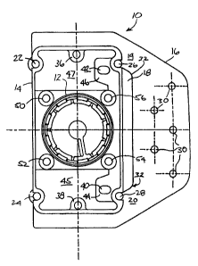
Figure 1 shows a backing plate indicated generally at 10 according to the
present invention.
The backing plate includes a tubular section 12, a continuous perimeter wall
14 and a side
flange 16. An opening 18 separates the side flange 16 from the mounting plate
10 except for
16 lands 19 and 201ocated at the top and the bottom respectively.
Partially formed in the side wall 14 are a plurality of openings 22, 24, 26,
28, 36 and 38
which are intended to accept fasteners such as screws or the like. Wire loop
holes 40 and 42
are provided on flanges 44 and 46 which extend into openings 45 and 47
respectively.
Further, four mounting openings 50, 52, 54 and 56 are shown located around the
perimeter of
21 the tubular portion 12. While any specific configuration of openings 22,
24, 26, 28, 36, 38,
50, 52, 54 and 56 can be used, it has been found that the configuration of the
openings as
shown is preferred, because this configuration is generally universal; a
majority of the inlet
valve cover plates presently in the trade are accommodated by this pattern of
openings.
As can be seen in the side view, in Figure 2, the apertures 22 and 24 include
rearward
26 extensions 58 and 60 which provide enough material for a fastener such a
screw to be firmly
gripped. Also, the tubular portion 12 can be seen extending rearwardly from
the plane of the
plate 10. The tubular portion 12 preferably ends with chamfered end portion
13.
2157534
-5-
1 In Figure 3, it can be seen that the side mounting flange 16 is relatively
thin as compared to
the balance of the backing plate and is attached at the side edge to the
backing plate. The
preferred thickness t for the flange 16 is 0.060 inches, and it is preferred
to form a plurality of
preformed nailing or other fastener holes 30 in the flange to facilitate the
attachment of the
flange to a stud or the like. Further a gentle curve is preferred to define
the lower and upper
6 borders of the opening 18, as shown by arrow 32. This curve, in combination
with a tapering
of thickness as shown at 31 in Figure 3, helps ensure that a break off line
for the flange is
generally parallel to the side edge of the backing plate. It will be
appreciated that scoring or
other techniques could also be used to cause the flange to break along the
desired line
adjacent to the side edge of the backing plate.
11 Turning to Figure 4, the tubular section 12 is shown in larger view with
the vacuum opening
61. The tubular section includes a plurality of forward and rearward
castellations indicated as
62 and 64 respectively. Each castellation is canted slightly towards the
opposing row of
castellations and is preferably placed opposite to a space formed in the
facing row of
castellations. In this manner, the rows of castellations can grip a sealing
member, such an 0-
16 ring 65, securely. Thus, it is unlikely that the sealing 0-ring or gasket
will be accidentally
pulled or sucked out of the castellations. The castellations are preferably
formed with a taper,
so a broader base is adjacent to the 0-ring 65. This is indicated by the
angled lines with
arrows 63. The taper facilitates molding the castellations. The preferred form
of the sealing
ring is a # 130. The castellations may be 0.045 inches thick, and need to
extend out from the
21 tubular section enough to grip the preferred sealing ring. Good results
have been achieved
using nine castellations in each row, evenly spaced about the inside perimeter
of the tubular
section. More or less could be used, however, by varying the length of each
castellation.
Figure 5 shows the same view as Figure 4 except that the removable protective
element 66 is
shown. As can be seen, a plurality of thin webs 68 extend from the main body
of the
26 protective element (which may be referred to as a router disk) across to an
inner surface 69 of
the castellations 62. In the most preferred embodiment, the attachment points
are formed on
the forward, or outward row of castellations. This facilitates the molding, in
one piece, of the
fitting with removable seal protector. In this sense it will be appreciated
that the reference to
the forward or outward position is to the position which the removable
protective element 66
CA 02157534 2006-02-28
-6-
i takes relative to the seal when the backing plate is installed on a stud or
the like. The
requirement is for the protective element 66 to be interposed between the
potential source of
damage (such as a router) and the part needing protection (the seal and
tubular portion).
Figure 6, is a side view of the tubular portion, as well as the castellations
62, 64 in dotted
outline. As can be seen they are formed in two parallel rows in which the
opposed rows are
6 spaced offset from each other. The ideal seal will be flexible and thus will
have a tendency to
be bent around each castellation, in an alternating or wavy pattern. This has
been found
effective to hold the seal in place against forces occurring when the cover
plate of the valve
assembly is inserted and withdrawn from the backing plate.
As can be seen in Figure 7, and in particular Figure 8, each web 68 which
extends between
11 the protective element and the tubular portion narrows or tapers. Good
results have been
achieved with a web that is .07 by .063 inches in cross section at the point
where it emerges
from the protective disk 66, and tapers to a .025 by .025 inch cross sectional
area where the
web joins the surface 69 of the castellations of the tubular portion (shaded
portion of Figure
9). It is preferred to form the taper on the side of the web 68 proximal to
the seal, but other
16 configurations are also possible as will be appreciated by those skilled in
the art. Figure 9
shows that the cross-sectional area of the web is smallest at the contact
point with the
castellation.
By tapering the web 68 as shown, the point of failure of the web 68 will be
adjacent to the top
of the castellation. There is a certain tolerance for there to be
disconformities or vestiges of
21 plastic left on the inner surface of the castellation, once the protective
element 66 has been
torn out. Essentially this tolerance is defined by the difference in height of
the castellations
62, 64, and the thickness of the sealing ring 65. To prevent the vestiges of
plastic from
interfering with the seal, it is most preferred to cause the webs 68 to
separate as close as
possible to the surface of the castellation. It will be appreciated by those
skilled in the art that
26 other configurations can also be used, provided they are sized and shaped
to permit the seal to
function properly.
The removable protective element 66 is shown with a central opening at 84. A
finger tab 86
2157534
-7-
i is provided which allows the removable element 66 to be gripped as shown in
Figure 10. As
the element is gripped and pulled, successive webs of the element are broken
one at a time.
In this manner, the protective element can be easily withdrawn from the
tubular portion 12.
Shown in dotted outline in Figure 10 as 100 is a portion of a cover plate or
valve, which is
inserted into the tubular portion 12, to form a complete assembly. The portion
100 seals
6 against sea165 as shown and may be simply pulled in and out as needed. Also
shown is
conduit 101 which surmounts the tubular portion 12.
Good results have been achieved by forming the router disk 66 from .063 inches
thick
material, and having the central opening about 0.5 inches in diameter. With
these dimensions
it has been found that the router disk 66 may be readily manipulated to pull
the same away
11 from the tubular section 12. Further, by making the finger tab 86 extend
slightly above the
plane defining the opening of the vacuum inlet tubular portion 12, the easy
manipulation of
the finger tab 86 is achieved. It is preferred to avoid projecting the finger
tab too far into the
space where a router might be expected to pass during installation of the
overmounted
drywall. It will be appreciated that what is desired is to position the finger
tab 86 in a manner
16 that balances the risk of it being in the way during installation with the
desire for the finger
tab to be easily accessed for removing the router disk.
In Figure 10, it can now be appreciated how the present invention operates.
Turning to Figure
1, the backing plate 10 can be positioned as necessary on a stud or the like
where the end of
the vacuum conduit is located. In some cases, it may not be necessary to
attach the mounting
21 flange to an adjacent stud, in which case, the flange can simply be broken
off along the line of
the opening 18.
Once the backing plate 10 is secured in position, a drywall installer can
press drywall over the
top of it. Then, using a router, and guided by the inside edge of the
perimeter wall 14, a
drywall installer can form an opening in the drywall which exactly matches the
perimeter
26 wall. During the process, the removable protective cover will be protecting
the damageable
rubber sea165. Further, debris and other blocking material will be prevented
from entering
into the vacuum system through the tubular part 12 of the fitting 10. Once the
drywall is
installed, and it is necessary to insert an inlet valve 100, then the
protective element 66 can
CA 02157534 2006-02-28
-8-
i simply be gripped at 86 and pulled away from the internal surface of tubular
portion 12.
Because the webs 70 will break adjacent to the internal surface of the tubular
element 12, any
disconformities caused or vestiges left will be hidden below the level of the
seal 65, or the
castellations 62, 64 depending where the webs attach. Thus, they will not
interfere in any
way with the ability of a good vacuum seal to be formed between the inlet
valve 100 and the
6 seal 86 mounted in the mounting plate 10.
Although the most preferred form of the invention is to have the removable
cover attach to
the tubular section on the castellations, it will be appreciated that the
attachment could also be
achieved at other points along the tubular portion 12, closer to the outside
edge. However for
maximum protection of the seal 65 and to ensure that the protective element 66
is not
11 prematurely broken or removed, it is preferred to mount it in the tubular
section at or about
the castellations 62, 64, as shown. Also, during molding, the castellation
forming parts of the
molds act as "gates" for the castellation webs which facilitates consistent
molding results.
Of course, if the castellations were to be replaced with a continuous lip, the
protective
element 66 could be anchored to such a continuous lip or anywhere on the
inside tubular
16 portion.
Further, although the most preferred form of the invention is to integrally
form the removable
cover at the time the backing plate is formed, the present invention also
comprehends the
removable cover being separately molded and simply press fit into position.
However this is
less preferred because of the problems of separate assembly being required and
that any such
21 press fit protective element is more likely to become unintentionally
separated leading to a
premature loss of protection for the seal and tubular portion.
It will be appreciated by those skilled in the art that while the foregoing
makes reference to a
preferred embodiment of the invention, various modifications and alterations
can be made
without departing from the spirit or the scope of the invention. For example,
while reference
26 has been made to the removable protective element 66 being attached to the
castellations, it
could be attached anywhere along the tubular portion 12, provided that
protection was
provided to the sea165 and that any plastic vestiges left over when the disk
66 is removed do
not interfere with the ability to form a good seal between seal 65 and tube
100 of the inlet
valve.