Note : Les descriptions sont présentées dans la langue officielle dans laquelle elles ont été soumises.
21608~3
TITLE
Article mounting assembly for a vehicle mounted carrier
v~L.lOR(S)
Ernest Hirschfeld
FIELD OF THE lNv~NllON
The present invention relates to vehicle mounted carriers
having an upright primary support member with a bottom end
adapted for attachment to a square tube trailer hitch on a
vehicle and a top end having means to secure articles to the
primary support member.
BACKGROUND OF THE lNv~..llON
Most vehicle mounted carriers are intended to transport
a particular article. For this reason, patents relating to
vehicle mounted carriers are usually titled as bicycle
carriers, tire carriers, ski carriers and the like. As one
might expect, the bicycle carriers are not particularly suited
for carrying skis, and vice versa.
SUMMARY OF THE lNv~L.llON
What is required is a vehicle mounted carrier that can be
used for a wide variety of articles.
According to the present invention there is provided an
improved article mounting assembly for a vehicle mounted
21608~3
carrier. This particular style of vehicle mounted carrier has
an upright primary support member with a bottom end adapted for
attachment to a square tube trailer hitch on a vehicle and a
top end having means to secure articles to the primary support
member. The improvement includes a tubular primary upright
support member having a top end, a bottom end and an interior
bore. A lower mounting member is provided having a first
portion and a tubular second portion. The first portion has
article receiving means. The second portion has an interior
bore that telescopically receives the top end of the primary
support member. Stop means are provided to limit the relative
telescopic movement of the tubular second portion of the lower
mounting member and the primary support member. An upper
mounting member is provided having a first portion and a second
portion. The first portion has article receiving means that
cooperate with the article receiving means of the lower
mounting portion. The second portion is telescopically
received in the interior bore of the primary support member.
Lock means are provided to lock the second portion in relative
telescopic position within the primary support member.
The vehicle mounted carrier, as described above, is
extremely versatile. The primary support member can be mounted
at the rear of a vehicle with the lower and upper mounting
members oriented away from the vehicle, toward the vehicle, to
the left side of the vehicle or to the right side of the
vehicle. When cylindrical tubing is used, there is a risk of
the lower mounting member rotating relative to the primary
support member. This problem can be avoided when the top end
of the primary upright support member and the second portion
of the lower mounting member are both fabricated from square
tubing.
The upper mounting member and the lower mounting member
can be spaced whatever distance apart is necessary to hold the
article securely. They can also be formed in a variety of
compatible shapes. It is preferred, however, that the lower
~160~6~
-
mounting member i8 a generally "L" shaped bracket with the
article receiving means on the first portion including a
plurality of arcuate depressions. It is, similarly, preferred
that the upper mounting member is a generally "L" shaped
bracket with the article receiving means on the first portion
including a plurality of arcuate depressions.
Although beneficial results may be obtained through the
use of the improved article mounting assembly for a vehicle
mounted carrier as defined above, it is sometimes a problem
getting a profile for one set of depressions that will
accommodate a wide variety of articles. Even more beneficial
results may be obtained when a generally planar resilient
deformable gasket extends along the first portion of the lower
mounting member and the first portion of the upper mounting
member. A gasket, as described, tends to deform to conform to
the shape of an article inserted into one of the arcuate
depressions.
There are a variety of stop means that can be used. The
one that is preferred involves positioning an inwardly
projecting flange in the interior bore of the lower mounting
member which engages a top peripheral edge of the primary
upright support member. There are, similarly, a variety of
lock means that can be used. The one that is preferred
involves positioning an inclined plane wedge member at a lower
end of the second portion of the upper mounting member. A bolt
is provided having a head positioned at a top end of the second
portion of the upper mounting member and a lower end engaging
the inclined plane wedge member. The inclined plane wedge
member is movable into a locking position by rotation of the
bolt.
BRIEF DESCRIPTION OF THE DRAWINGS
These and other features of the invention will become more
2160863
-
apparent from the following description in which reference is
made to the appended drawings, wherein:
FIGURE 1 is an exploded side elevation view of an improved
article mounting assembly for a vehicle mounted carrier
constructed in accordance with the teachings of the present
invention.
FIGURE 2 is a side elevation view of the article mounting
assembly illustrated in FIGURE 1.
FIGURE 3 is a side elevation view of the article mounting
assembly illustrated in FIGURE 1, mounted on a vehicle with the
lower and upper mounting members positioned toward the vehicle.
FIGURE 4 iS a side elevation view of the article mounting
assembly illustrated in FIGURE 1, mounted on a vehicle with the
lower and upper mounting members positioned away from the
vehicle.
FIGURE 5 is a rear elevation view of the article mounting
assembly illustrated in FIGURE 1, mounted on a vehicle with the
lower and upper mounting members positioned toward the left
side of the vehicle.
FIGURE 6 is a rear elevation view of the article mounting
assembly illustrated in FIGURE 1, mounted on a vehicle with the
lower and upper mounting members positioned toward the right
side of the vehicle.
FIGURE 7 is a detailed side elevation view of a gasket
portion of the article mounting assembly illustrated in FIGURE
1.
FIGURE 8 is a detailed side elevation view of a primary
upright support member of the article mounting assembly
illustrated in FIGURE 1.
DE~ATT~n DESCRIPTION OF THE PREFERRED EMBODIMENT
The preferred embodiment, an article mounting assembly for
a vehicle mounted carrier generally identified by reference
numeral 10, will now be described with reference to FIGURES I
2160863
-
through 7.
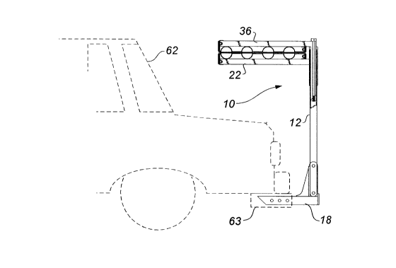
Referring to FIGURE 1, there is illustrated an upright
primary support member 12 with a bottom end 14 and a top end
16. Bottom end 14 has an adaptor 18 which is intended for
insertion into a square tube trailer hitch on a vehicle. Top
end 16 has means to secure articles to primary support member
12, which serve as the subject matter of this invention.
Referring to FI¢URE 2, in accordance with the present
invention top end 16 of primary support member 12 is fabricated
from tubing and, as such, has an interior bore 20. It is
preferred that the tubing be square. Referring to FIGURE 1,
a generally "L" shaped lower mounting member 22 is provided
having a first portion 24 and a second portion 26. First
portion 24 extends substantially horizontally and has a
plurality of arcuate article receiving depressions 28. Second
portion 26 is also fabricated from square tubing and has an
interior bore 30. Interior bore 30 telescopically receives top
end 16 of primary support member 12. An inwardly projecting
flange 32 in interior bore 30 of lower mounting member 22
engages a top peripheral edge 34 at top 16 of primary support
member 12 to limit the relative telescopic movement of second
portion 26 of lower mounting member 22 and primary support
member 12. A generally "L" shaped upper mounting member 36
is provided having a first portion 38 and a second portion 40.
First portion 38 extends substantially horizontally and has a
plurality of arcuate article receiving depressions 42. Arcuate
article receiving depressions 42 of upper mounting member 36
cooperate with arcuate article receiving depressions 28 of
lower mounting member 22 to form generally circular article
receiving cavities, generally indicated in FIGURE 2 by
reference numeral 44. Second portion 40 of upper mounting
member 36 is telescopically received in interior bore 20 of
primary support member 12, as illustrated in FIGURE 2. An
inclined plane wedge member 46 is positioned at a lower end 48
of second portion 40 of upper mounting member 36. Lower end
~1608S3
48 of second portion 40 of upper mounting member is inclined
at an angle. A bolt 50 extends through upper mounting member
36. Bolt 50 has a head 52 positioned at an upper end 54 of
second portion 40 and a lower end 56 engaging inclined plane
wedge member 46. Inclined plane wedge member 46 is movable by
rotation of bolt 50 to lock second portion 40 in relative
telescopic position within interior bore 20 of primary support
member 12. A first generally planar resilient deformable
rubber gasket 58 extends along first portion 24 of lower
mounting member 22. A second generally planar resilient
deformable rubber gasket 60 extends along first portion 38 of
upper mounting member 36 parallel to first deformable ga~ket
58. Referring to FIGURE 7, gaskets 58 and 60 deform to
conform to the ~hape of an article 70 inserted into one of
circular article receiving cavities 44. In this case, article
70 is a pair of skiis. Referring to FIGURE 8, it can be seen
that primary support member 12 is pivotally mounted at bottom
end 14 to adaptor 18. When cotter pin 72 is pulled out of
aperture 74 primary support member 12 pivots about a horizontal
axis defined by pivot pin 76. This feature allows bicycles to
be set onto the ground during loading and unloading, and allows
improved access to the rear or trunk area of the vehicle when
vehicle mounted carrier 10 is in place. An underlying lip 78
projects from adaptor 18 and serves as stop means to limit
pivotal movement of primary support member 12.
The use and operation of vehicle mounted carrier 10 will
now be described with reference to FIGURES 1 through 7.
Referring to FIGURES 3 through 6, vehicle mounted carrier 10
is secured to a vehicle 62 by inserting adaptor 18 into a
square tube trailer hitch 63. When this is done primary
support member 12 is positioned vertically behind vehicle 62.
The versatility of vehicle mounted carrier 10 lies in the
article mounting assembly, as previously described. Referring
to FIGURES 1 and 2, lower mounting member 22 is positioned onto
primary mounting member 12 inserting top 16 of primary mounting
member 12 into interior bore 30 of second portion 26 until top
2160863
peripheral edge 34 engages inwardly projecting flange 32.
Referring to FIGURE 3 lower mounting member 22 can be
positioned toward vehicle 62. Referring to FIGURE 4, lower
mounting member 22 can be positioned extending away from
vehicle 62. Referring to FIGURE 5, lower mounting member 22
can be positioned toward a left side 64 of vehicle 62.
Referring to FIGURE 6 lower mounting member 22 can be
positioned toward a right side 66 of vehicle 62. This
difference in orientation is very important, as it enables the
space requirements of different articles to be accommodated.
In addition, the needs of various vehicles can be accommodated.
For example, a vehicle with a rearwardly facing door requires
lower mounting member 22 to be positioned to either left side
64 or right side 66 in order to permit the door to be opened.
Once lower mounting member 22 is in position on primary support
member 12, an article 70 can be positioned in arcuate article
receiving depressions 28, as illustrated in FIGURE 7. Of
course, article 70 might not maintain its position if vehicle
62 were set in motion, so upper mounting member 36 is
positioned onto primary support member 12. Article 70 is
prevented from coming out of depressions 28 of lower mounting
member 22 by upper mounting member 36. As previously
described, arcuate article receiving depressions 42 of upper
mounting member 36 cooperate with arcuate article receiving
depressions 28 of lower mounting member 22 to form generally
circular article receiving cavities 44. Referring to FIGURES
1 and 2, upper mounting member 36 is positioned on primary
support member 12 by inserting second portion 40 of upper
mounting member 36 into interior bore 20 of primary support
member 12, as illustrated in FIGURE 2. Inclined plane wedge
member 46 is then used to lock upper mounting member 36 in
position. In order to tighten inclined plane wedge member 46
a tool is placed upon head 52 of bolt 50, and bolt 50 is
rotated. The rotation of bolt 50 results in inclined plane
wedge member 46 rotating in relation to lower inclined end 48
of second portion 40 of upper mounting member 36, until
inclined plane wedge member 46 and lower inclined end 48 turn
2160~63
-
sufficiently to wedge second portion 40 of upper mounting
member within interior bore 20 of primary support member 12.
Referring to FIGURE 7, when article 70 is not arcuate in shape,
gaskets 58 and 60 deform to conform to the actual shape of
article 70, thereby adapting circular article receiving
cavities 44 to the required shape. Referring to FIGURE 8, when
access to the rear or trunk area of the vehicle i8 required
primary support member 12 can be pivoted out of the way by
pulling cotter pin 72 out of aperture 74 and pivoting primary
support member 12 about a horizontal axis defined by pivot pin
76.
It will be apparent to one skilled in the art that
modifications may be made to the illustrated embodiment without
departing from the spirit and scope of the invention as defined
by the Claims.