Note : Les descriptions sont présentées dans la langue officielle dans laquelle elles ont été soumises.
2l~2~a
Background of the Invention
This invention relates generally to a reservoir for
holding liquids such as hydraulic fluids and, more
specifically, to a reservoir having an end portion with a
relatively large opening adapted to be mounted to, for
example, a hydraulic manifold.
The invention is especially useful in a hydraulic
power pack of the type having a hydraulic pump located
inside the reservoir. In this instance, the open end
portion of the reservoir is sized to fit over the pump
prior to being secured to the manifold.
A generally cylindrical mounting ring is either
joined to or integrally formed at the open end of the
reservoir. The mounting ring is typically adapted to
receive threaded fasteners for securing the reservoir to
the manifold. An O-ring establishes a circumferential
seal between the internal cylindrical surface of the
mounting ring and an upwardly projecting cylindrical
portion of the manifold to seal the open end of the
reservoir.
Either plastic or steel reservoirs can be used for
storing hydraulic fluid in a hydraulic power pack.
Plastic reservoirs, however, offer several advantages
over comparable steel reservoirs. Plastic reservoirs are
relatively lightweight and will not corrode. In addi-
tion, plastic reservoirs can be made from a translucent
material to permit a quick visual check of the level of
oil in the reservoir. Despite these advantages, plastic
reservoirs have not been widely accepted for use in prior
hydraulic power packs.
The mounting ring of the reservoir is subjected to
continuous forces that tend to expand the cylindrical
portion of the mounting ring. Specifically, the radial
squeeze on the O-ring causes an outwardly directed force
on the cylindrical portion of the mounting ring. While
this force is relatively low, over time, the continuous
~162~0~
nature of the force caused by the 0-ring, combined with
the heating cycles experienced during normal operation of
the power pack, will cause a mounting ring which has been
made from a common plastic compound to relax and deform
outwardly. In those instances where the reservoir is
either above or horizontally level with the manifold, at
least a portion of the mounting ring is subjected to
additional outwardly acting forces due to hydrostatic
pressure caused by the weight of the fluid in the
reservoir. Eventually, relaxation of the mounting ring
will result in failure of the circumferential seal and
leakage of hydraulic fluid from the reservoir. For this
reason, prior mounting rings are typically made from a
metal having sufficient strength and stiffness to with-
stand the continuous forces of the open end of thereservoir.
Steel mounting rings are easily integrated with
steel reservoirs. For example, a steel mounting ring can
be welded to a steel body. Alternately, a steel mounting
ring may be integrally formed at the open end portion of
a steel reservoir. It is difficult, however, to secure a
steel mounting ring to a plastic body without the use of
an additional sealing arrangement between the body and
the mounting ring. As a result of the need for a steel
mounting ring and the difficulty in securing a steel
mounting ring to a plastic body, prior reservoirs for
power packs are typically made from steel or other suit-
able metal.
Summary of the Invention
The general aim of the present invention is to pro-
vide a new and improved plastic reservoir for use in a
hydraulic power pack.
A more detailed objective is to achieve the fore-
going by providing a mounting ring having a plastic por-
tion which is capable of being bonded to a plastic reser-
2l~2~a
voir body and having a metal reinforcing ring which is
encapsulated in the plastic portion. The metal ring
stiffens the plastic portion of the mounting ring to
prevent the mounting ring from deforming outwardly so as
to maintain the integrity of a circumferential seal esta-
blished at the internal periphery of the mounting ring.
Another detailed objective of the invention is to
provide outwardly extending metal projections which are
formed integrally with the metal ring and which are
encapsulated in substantially plastic mounting tabs for
reinforcing the mounting tabs.
These and other objects and advantages of the inven-
tion will become more apparent from the following
detailed description when taken in conjunction with the
accompanying drawings.
Brief Description of the Drawings
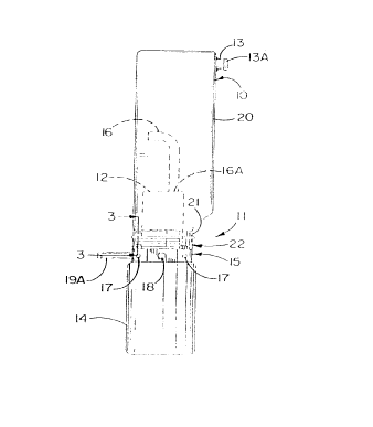
FIGURE 1 is a side view of a typical hydraulic power
pack equipped with a new and improved plastic reservoir
incorporating the unique features of the present inven-
tion.
FIG. 2 is an exploded perspective view of certain
parts of the hydraulic power pack.
FIG. 3 is an enlarged fragmentary cross-sectional
view taken substantially along the line 3-3 of FIG. 1.
FIG. 4 is an enlarged cross-sectional view taken
substantially along the line 4-4 of FIG. 1.
While the invention is susceptible of various modi-
fications and alternative constructions, a certain illus-
trated embodiment hereof has been shown in the drawings
and will be described below in detail. It should be
understood, however, that there is no intention to limit
the invention to the specific form disclosed, but on the
contrary, the intention is to cover all modifications,
alternative constructions and equivalents falling within
the spirit and scope of the invention.
~1~2DOO
Detailed Description of the Preferred Embodiment
For purposes of illustration, the present invention
is shown in the drawings as embodied in a plastic reser-
voir 10 (FIG. 1) which is especially suitable for use in
a hydraulic power pack 11.
The hydraulic power pack 11 includes the reservoir
10, a rotary-type hydraulic pump 12, an electric motor 14
and a manifold 15. The reservoir and the pump are
secured to the manifold, the pump being located inside
the reservoir. The motor is secured to the manifold
oppositely of the pump. The output shaft (not shown) of
the motor extends through an opening 16 (FIG. 2) in the
manifold and is coupled to the input shaft (not shown) of
the pump. Threaded openings 17 are spaced around the
outer periphery of the manifold and are adapted to
receive threaded fasteners for mounting the hydraulic
power pack to a machine or other support member.
During normal operation of the hydraulic power pack
11, the pump 12 is operable to draw hydraulic fluid from
the reservoir 10 and to deliver a supply of pressurized
hydraulic fluid to a hydraulic circuit. Specifically,
electric power is supplied to the motor 14 which, in
turn, drives the pump. The pump draws fluid from the
reservoir through an inlet opening 16A. The pump
delivers pressurized fluid to a port formed in the mani-
fold 15 whereupon the fluid flows through internal
passages formed in the manifold and to an outlet port 19.
A hydraulic line l9A which is connected to the outlet
port 19 delivers the pressurized hydraulic fluid to the
hydraulic circuit.
The reservoir 10 is filled with hydraulic fluid
through a fill port 13 and stores the supply of hydraulic
fluid for the pump 12. The volumetric capacity of the
reservoir is greater than the volumetric capacity of the
closed hydraulic system to insure that, assuming that the
reservoir was full before the motor was started, there is
2~20~
an adequate supply of fluid available for use by the pump
to pressurize and fill the system. The reservoir is
initially filled by simply pouring fluid into the reser-
voir through a fill port 13. The reservoir is vented to
ambient through the breather cap 13A which closes the
fill port.
Typically, the power pack 11 is used in a closed
hydraulic system where a limited volume of hydraulic
fluid is needed in the system. For example, the power
pack may be utilized to extend a hydraulic cylinder.
When the electric motor 14 is turned on, the hydraulic
pump 12 pressurizes the cylinder. Hydraulic fluid then
flows from the power pack to the cylinder as the cylinder
extends. When the cylinder reaches the end of its
stroke, hydraulic fluid stops flowing from the power
pack. A release valve is typically located in a return
line connecting the cylinder to the return port 18 of the
power pack to release the pressure from the cylinder.
The hydraulic fluid is then returned to the reservoir by
way of the return port and internal passages in the mani-
fold 15.
The power pack 11 is illustrated in a vertical posi-
tion with the reservoir 10 above the manifold 15 and the
pump 12, including the inlet to the pump 16A, is immersed
in hydraulic fluid. In many cases, however, the power
pack may be mounted in a generally horizontal position
with the pump only partially immersed in hydraulic fluid.
In this instance, a pipe or tubing 16 is secured to the
inlet 16A of the pump and bent in a manner so that the
open end of the tubing is always immersed in the hydrau-
lic fluid. Alternately, the reservoir may be located
below the manifold and the tubing will extend generally
downwardly so that, again, the open end of the tubing is
immersed in the fluid. Advantageously, the fill port 13
for filling the reservoir with hydraulic fluid is located
on the reservoir according to the intended orientation of
the reservoir. Specifically, an opening is formed in the
2`16~U00
reservoir in a location that will always be above the
level of the fluid in the reservoir. The fill port is
then welded or otherwise secured to that opening. In
this way, the fill port is always positioned above the
maximum level of fluid in the reservoir.
The reservoir 10 is formed with a body 20 and an
open end portion 21 in the form of a generally cylin-
drical neck. A generally cylindrical mounting ring 22
having an internal cylindrical surface 23 projects
axially from the neck portion 21 of the reservoir. The
mounting ring is normally bonded or welded to the neck
portion 21. Alternately, the mounting ring may be inte-
grally formed at the lower end portion of the reservoir.
The mounting ring and the neck portion of the reservoir
are adapted to fit over the pump so that the mounting
ring may be located adjacent the manifold 15.
Typically, the mounting ring 22 is formed with
integral and angularly spaced ears or mounting tabs 24
for securing the reservoir 10 to the manifold 15. The
mounting tabs are adapted to mate with a mounting flange
25 of the manifold. The tabs extend generally radially
relative to the neck portion 21 and are formed with open-
ings 27 which align with threaded openings 28 in the
mounting flange 25. The reservoir is secured to the mani-
fold by threaded fasteners 26 which are slidably received
in the openings 27 and which are threaded into the open-
ings 28. Alternately, the reservoir may be secured to
the manifold by any suitable means such as by forming an
internal thread on the mounting ring to mate with an
external thread on the cylindrical portion 31 of the
manifold or by providing for fasteners inserted radially
inwardly through the mounting ring and received in
threaded openings in the cylindrical portion of the
manifold.
A resilient preformed gasket or 0-ring seal 29 pre-
vents leakage of hydraulic fluid from the reservoir 10.
The 0-ring is located in a circumferentially extending
0 ~ ~
groove 30 formed in an upwardly extending cylindrical
portion 31 of the manifold 15. The external cylindrical
surface 33 of the portion 31 is slidably received into
the cylindrical portion or neck ring 22A of the mounting
ring 22 so that the O-ring establishes a radial seal
against the internal cylindrical surface 23 of the neck
ring.
Prior neck rings 22A made from common plastic com-
pounds are generally unable to withstand the outwardly
directed forces acting on the neck ring. Specifically,
prior plastic neck rings tend to expand due to the radial
force of the O-ring resulting from the radial squeeze on
the O-ring. Eventually, the radial squeeze between the
neck ring and the O- ring is reduced and hydraulic fluid
leaks from the reservoir. Relaxation of the neck ring is
accelerated by the normal heating of the fluid in the
reservoir when the pump is running and by the hydrostatic
pressure head that develops when at least a portion of
the neck ring is located below the fluid in the reser-
voir. As a result, prior mounting rings 22 and priorreservoirs are typically made from a suitable metal.
In accordance with the present invention, a metal
ring 36 (FIG. 4) is encapsulated in a substantially plas-
tic neck ring 22A. The metal ring reinforces the plastic
portion of the mounting ring 22 so that the substantially
plastic neck ring has sufficient stiffness and hoop
strength to withstand long term exposure to normally
encountered radially directed forces in the reservoir 10
and to repeated heating cycles of the fluid in the reser-
voir. Further, the plastic portion of the mounting ringmay be easily bonded or secured to the neck portion 21 of
a plastic reservoir. As a result, a plastic reservoir
may be used in the hydraulic power pack 11. Preferably,
the plastic reservoir is made from a translucent plastic
so that the level of the fluid can be visually monitored.
This obviates the need for a dipstick arrangement or for
~162~00
a visual sight-glass to check the fluid level in the
reservoir.
More specifically, the metal reinforcing ring 36 is
formed as a continuous ring. Preferably, the metal ring
is completely encapsulated in plastic. In this way, the
plastic portion of the mounting ring 22 protects the
metal ring from corrosion. Further, the plastic internal
periphery of the mounting ring 22 defines the smooth
cylindrical surface 23 which engages the O-ring 29.
The upper plastic portion 39 of the mounting ring 22
is joined to the neck portion 21 of the plastic reservoir
10 by heat bonding, ultrasonic bonding or welding, adhe-
sive bonding, or any other suitable means.
When the reservoir 10 is secured to the manifold 15,
the metal reinforcing ring 36 is axially aligned with the
O-ring 29 and extends axially, in both directions, beyond
the O-ring. The reinforcing ring is sized to insure that
the hoop strength and stiffness of the mounting ring 22
will withstand the weight of hydraulic fluid in the
reservoir without substantial deformation. In this way,
the reinforcing ring maintains the integrity of the
radial seal between the manifold lS and the mounting
ring .
Preferably, the metal ring 36 is formed having inte-
gral and radially outwardly extending metal projections
37 which are completely encapsulated in plastic. The
plastic-encapsulated metal projections 37 define the
mounting tabs 24. The metal projections are formed with
openings 38 that align with the openings 27 in the mount-
ing tabs for slidably receiving the fasteners 26. In
this way, the fasteners 26 will clamp onto the encapsu-
lated metal projections when the reservoir is secured to
the manifold 15 so that the metal projections reinforce
the mounting tabs.
From the foregoing, it will be apparent that the
present invention brings to the art a new and improved
plastic reservoir 10 having a substantially plastic
~1~20Q~
mounting ring 22 capable of being welded or bonded to the
neck portion 21. By virtue of an encapsulated metal
reinforcing ring 36, the strength and stiffness of the
substantially plastic mounting ring are significantly
enhanced. The mounting ring is capable of withstanding
long term exposure to outwardly directed radial forces
and to the normal heating of the hydraulic fluid in the
reservoir 10 so as to maintain the integrity of a circum-
ferential seal at the internal surface of the mounting
ring.