Sélection de la langue

Search

Sommaire du brevet 2163142 

Énoncé de désistement de responsabilité concernant l'information provenant de tiers

Une partie des informations de ce site Web a été fournie par des sources externes. Le gouvernement du Canada n'assume aucune responsabilité concernant la précision, l'actualité ou la fiabilité des informations fournies par les sources externes. Les utilisateurs qui désirent employer cette information devraient consulter directement la source des informations. Le contenu fourni par les sources externes n'est pas assujetti aux exigences sur les langues officielles, la protection des renseignements personnels et l'accessibilité.

Disponibilité de l'Abrégé et des Revendications

L'apparition de différences dans le texte et l'image des Revendications et de l'Abrégé dépend du moment auquel le document est publié. Les textes des Revendications et de l'Abrégé sont affichés :

  • lorsque la demande peut être examinée par le public;
  • lorsque le brevet est émis (délivrance).
(12) Brevet: (11) CA 2163142
(54) Titre français: APPAREIL D'ECLAIRAGE MURAL
(54) Titre anglais: WALL MOUNTABLE LIGHTING FIXTURE
Statut: Réputé périmé
Données bibliographiques
(51) Classification internationale des brevets (CIB):
  • F21V 7/09 (2006.01)
  • F21S 8/00 (2006.01)
  • F21V 7/00 (2006.01)
  • F21V 21/02 (2006.01)
(72) Inventeurs :
  • JOHNSON, DENNIS E. (Etats-Unis d'Amérique)
  • SMITH, DEAN R. (Etats-Unis d'Amérique)
(73) Titulaires :
  • SPI LIGHTING, INC. (Etats-Unis d'Amérique)
(71) Demandeurs :
(74) Agent: BORDEN LADNER GERVAIS LLP
(74) Co-agent:
(45) Délivré: 1999-09-21
(22) Date de dépôt: 1995-11-17
(41) Mise à la disponibilité du public: 1997-05-02
Requête d'examen: 1997-01-10
Licence disponible: S.O.
(25) Langue des documents déposés: Anglais

Traité de coopération en matière de brevets (PCT): Non

(30) Données de priorité de la demande:
Numéro de la demande Pays / territoire Date
08/551,386 Etats-Unis d'Amérique 1995-11-01

Abrégés

Abrégé anglais


Disclosed herein is a light unit for narrow hallways
A reflector housing is provided to project light from a
vertically extending bulb in an indirect manner, so as to
provide a substantially laterally extending light
pattern. The reflector has internal reflecting surface
surrounding the longitudinal axis of the bulb.

Revendications

Note : Les revendications sont présentées dans la langue officielle dans laquelle elles ont été soumises.


- 9 -
CLAIMS

We claim:

1. A lighting fixture mountable on a support,
comprising:
a reflector housing having an internal cavity
defined by at least two frontal lateral lobes, a rear
wall, a bottom wall and an upper opening; and
an electrical lamp extending primarily
vertically in the cavity;
the bottom wall having a reflector surface
positioned to reflect light from said electric lamp at
least partially upwards;
the rear wall having a reflector surface
positioned to reflect light from said electric lamp at
least partially forward; and
the frontal lateral lobes having reflector
surfaces positioned to reflect light from said electric
lamp upward, rearward, and laterally.


2. The fixture of claim 1, wherein the rear wall
has at least two sets of reflector segments, one set
being suitable to reflect light laterally outward from
said electric lamp and a second set being suitable to
reflect light from said electric lamp laterally inward
across the electric lamp.

3. The fixture of claim 1, wherein the bottom wall
has a hole for receiving a light socket, and there is a
frontal lower reflector surface on the reflector housing


- 10 -
adjacent and below the lamp for reflecting light
upwardly.

4. The fixture of claim 1, wherein the electric
lamp has a longitudinal axis in an essentially vertical
plane.

5. The fixture of claim 1, where the fixture is
mounted on and at least partially in the support such
that the reflector rear wall is positioned at least
partially behind a portion of the front surface of the
support adjacent the fixture.


6. The fixture of claim 1, further comprising a
decorative shade mountable forward and under the
reflector housing, the shade also having an upper
opening.

Description

Note : Les descriptions sont présentées dans la langue officielle dans laquelle elles ont été soumises.

2163142
-


WALL h~uNlABLE LI~llN~ ~l~-lUKE

Technical Field

The present invention relates to indirect lighting
fixtures. It appears to be especially well suited for
use in lighting narrow hallways.

Backqround Art

The art has developed a variety of systems for
lighting narrow hallways. One system uses overhead
downlights. However, this solution may be difficult to
implement in narrow hallways that already have low
ceilings, and/or where it is desired to keep the space
between floors to the minimum (for cost or other reason).
Another common system mounts lighting fixtures along
the sides walls of the hallways. However, in order to
obtain adequate light, such fixtures have in the past
often projected significantly out from the wall. This
system must now be changed due to laws and regulations
(the American Disabilities Act) which limit the placement
of lighting fixtures in narrow hallways where the
fixtures project out more than four inches from the side
walls.
If one uses conventional side wall fixtures that
extend out four inches or less from the wall, one needs
to use more fixtures along the wall. This increases the
installation and maintenance cost, and leads to energy
inefficiency. As such, a need exists for an improved
lighting fixture for use in narrow hallways which does
not project out more than four inches into the hallway,
yet efficiently provides adequate light along the
hallway.

2163142 -)
-

.


Disclosure Of The Invention

In one aspect, the invention provides a lighting
fixture mountable on a support. There is a reflector
~ housing having an internal cavity defined by at least two
frontal lateral lobes, a rear wall, a bottom wall and an
upper opening, and an electrical lamp extending primarily
vertically in the cavity.
The reflector housing bottom wall has a reflector
surface positioned to reflect light from the electric
lamp at least partially upward. The rear wall has a
reflector surface positioned to reflect light from the
electric lamp forward and also laterally. The frontal
lateral lobes both have reflector surfaces positioned to
reflect light from the electric lamp upward, rearward,
and also laterally. Preferably, the rear wall has at
least two sets of reflector segments, one set for
reflecting light laterally outward, and a second set for
reflecting light laterally inward across the electric
lamp.
In an especially preferred form the bottom wall has
an opening therethrough that is suitable to receive a
light socket for accommodating a metal halide,
fluorescent, or incandescent lamp, and the top of the
lamp is below the top edge of the reflector housing that
is directly in front of the lamp.
In other embodiments, the electric lamp has a
longitudinal axis which is in an essentially vertical
plane, the rear wall of the reflector is at least
partially behind the front of the portion of the hallway
adjacent the fixture, and the electrical lamp is linked
to an electrical control such as a magnetic ballast or
the like.

2163142


--3--
The fixture provides an indirect lighting system
which efficiently projects a predominantly lateral
lighting pattern to illuminate narrow hallways.
Importantly, even light initially rearwardly or
downwardly directed from the bulb is reflected out and
efficiently used.
In another aspect there is also a decorative shade
in front of and under the reflector, and neither the
shade nor the reflector projects out into the hallway
more than four inches.
Using one example form of the invention, two or more
foot candles of light can be achieved all the way across
a hallway for twelve lateral feet in both directions.
Thus, a hallway can be illuminated with a reduced number
of fixtures, without violating ADA requirements. Also,
the lighting is inviting and warm, and it gives the
aesthetic feel of a secure area.
The objects of the present invention therefore
include providing a lighting fixture of the above kind
which:
(a) has a wide, indirect light pattern whose main
distribution is emitted at 115~ from vertical and at + -
67.5~ laterally;
(b) provides for spacing distances much greater
than those typical with ADA compliant wall sconces;
(c) provides evenly balanced uniform lighting
consistent with Illuminating Engineering Society Of North
America reco~men~tions; and
(d) efficiently uses energy.
These and still other objects and advantages of the -
present invention will be apparent from the description
which follows. The following description is merely an
example of the present embodiment. The claims should be

2163142


looked to in order to appreciate the full scope of the
invention.

Description Of The Drawinqs

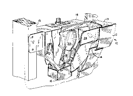
Fig. 1 is a frontal, left, perspective view of a
wall mountable lighting fixture embodying the present
invention;
Fig. 2 is an enlarged, fragmented, perspective view
thereof;
Fig. 3 is a reflector portion of the present
invention, together with an electric light;
Fig. 4 is a top plan view, in partial section, of a
portion of the fixture mounted on and in a hallway wall
albeit with a different rear reflector;
Fig. 4A is a view similar to Fig 4, but with the Fig
3 rear reflector;
Fig. 5 is a front elevational view of a box for
connecting electrical components;
Fig. 6 is a partial sectional view taken along line
6-6 of Fig. 4;
Fig. 7 is a front elevational view of the Fig. 3
reflector;
Fig. 8 is a top plan view of the Fig. 3 reflector;
Fig. 9 is a sectional view taken on line 9-9 of Fig.
8;
Fig. 10 is a rear elevational view of the Fig. 3
reflector;
Fig. 11 is a top plan ~iew of a rearward portion of
the Fig. 3 reflector;
Fig. 12 is a chart showing candle power distribution
of the invention for one embodiment;

2163142


Fig. 13 is an isocandle curve for the Fig. 12
embodiment.

Best Modes For CarrYinq Out The Invention

As shown in Figs. 1, 2 and 4, there is a lighting
fixture (generally 10) mounted against (and partially in)
a wall support 11. Outer decorative shade 12 has an
upper opening 13 and a lower slot 14.
There are the usual wall studs 15 on to which is
mounted a recessed housing 18 via brackets 17 as best
seen in Figures 2 and 5. A conventionai ballast/control
16 is mounted into the housing and provides the
electrical characteristics to operate metal halide,
fluorescent, or incandescent lamps or bulbs 20.
The socket 19 and bulb 20 extend into the internal
cavity of reflector housing 24. The reflector is
preferably made of aluminum and can be manufactured in
one or two pieces. In the two piece embodiment (as
shown), it consists of a front wall 25 having two opposed
frontal, lateral reflecting lobes 26 and 27. In
addition, there is a rear wall 29 which has a series of
rear reflector lobes 30, 31, 32, and 33 (see Fig 4).
Light behind bulb 20 is reflected laterally outward from
lobes 31 and 32 and laterally inward across the bulb from
lobes 30 and 33.
Also, in the Fig 4 embodiment reflector segments 34-
39 reflect some light laterally outward and some across
in front of the bulb when directing light forward. The
Fig 4A reflector has a somewhat simpler shape in this
region.
The bulb 20 is tilted forward 15~ from vertical and
is essentially vertical (e.g. its longitudinal axis 23 is

2163142


substantially in a vertical plane and it is tilted less
than 45~, e.g. perferably 15~, from up or down). The top
of the reflector 28 directly in front of the bulb 20
extends higher than the bulb. Thus, those walking down a
hallway will not normally see a glare from the bulb as
the top of the fixture is typically positioned at about
6'6". The system is thus an indirect lighting system.
There is also a bottom wall 40 with segments 41-46
and hole 47. As noted in Fig. 6, adjacent the bulb 20
the light is reflected up and forward. Light reaching
the front lobes 26, 27 is reflected so that some of the
light reflects up onto the wall, albeit most projects
laterally.
Slot 14 also permits some light to be reflected down
from the ceiling back through the fixture along the
support.
With respect to the chart of Fig 12, the axes are
light intensities measured in candela from 90~ (level
with the light) to 180~ (up). The patterns are 0~
(dotted line) which depicts the light directed forward
from the front of the fixture, 45~ (solid line)
representing the light projected laterally out into the
hallway, 90~ (medium dashed line) indicating the light
projected laterally along the wall, and 180~ (long
dashes) which is the back light. It can be seen that the
light with greatest intensity occurs at a lateral angle
out into the hallway.
Fig. 13 is a top plan view with axis 2-10 being
distance (feet) in a direction perpendicular across the
hall and axis 2-14 being distance (feet) laterally along
the hallway. Note the footcandle level twelve feet down
the hallway and eight feet away from the wall. As a

-
2163142


result, such fixtures can be positioned 24 feet apart or
more, in a conventional hallway.
It will therefore be appreciated that the present
invention provides a unique solution for lighting narrow
S hallways without the need for overhead lights,
substantial projections into the hallways, or an
unacceptable number of fixtures. While particular
embodiments of the present invention have been described,
it should be appreciated the invention is not to be
limited to just these versions. Rather, other
embodiments are intended to be within the scope of the
invention.
For example, while the reflector and shade are shown
as having an upwardly open end, a glass lens can be
placed over the top of the fixture to prevent dust from
entering the reflector cavity. Further, while a
particular size of reflector has been shown, the upper
rear edge of the reflector (along the wall) can be
extended up a greater distance to provide a surface which
further reflects heat and light away from the wall
adjacent to the top of the reflector. This is preferred
for halide bulbs of 70 watts or more.
In another alternative, the ballast system used with
the lamp can have an emergency power supply which
2S operates the lamp (e.g. for ninety minutes) on battery
power if the AC power is shut off. Further, various
holes can be provided in the decorative shade which can
then be covered by transparent red or green inserts so as
to provide a visual indication to people walking down the
hallways regarding a proper emergency evacuation route.
Also, the system can be provided with a start-up
lighting option, such as a 25 watt quartz lamp, that
provides temporary lighting until the halide lamp reaches

2163142


thirty percent of its lighting output when the system is
first turned on.
It should also be appreciated that other forms of
electrical light such as fluorescent bar lamps, halogen
lamps or incandescent lamps can also be used. However,
substantially vertically disposed bulbs are desired as
primarily horizontal bulbs can yield dark spots
corresponding to the location of the light socket (or
require two bulbs to avoid such dark spots).
Industrial Applicability

This invention is useful in lighting narrow
hallways.

Dessin représentatif
Une figure unique qui représente un dessin illustrant l'invention.
États administratifs

Pour une meilleure compréhension de l'état de la demande ou brevet qui figure sur cette page, la rubrique Mise en garde , et les descriptions de Brevet , États administratifs , Taxes périodiques et Historique des paiements devraient être consultées.

États administratifs

Titre Date
Date de délivrance prévu 1999-09-21
(22) Dépôt 1995-11-17
Requête d'examen 1997-01-10
(41) Mise à la disponibilité du public 1997-05-02
(45) Délivré 1999-09-21
Réputé périmé 2009-11-17

Historique d'abandonnement

Il n'y a pas d'historique d'abandonnement

Historique des paiements

Type de taxes Anniversaire Échéance Montant payé Date payée
Le dépôt d'une demande de brevet 0,00 $ 1995-11-17
Enregistrement de documents 0,00 $ 1996-02-08
Taxe de maintien en état - Demande - nouvelle loi 2 1997-11-17 100,00 $ 1997-10-31
Taxe de maintien en état - Demande - nouvelle loi 3 1998-11-17 100,00 $ 1998-10-21
Taxe finale 300,00 $ 1999-06-22
Taxe de maintien en état - brevet - nouvelle loi 4 1999-11-17 100,00 $ 1999-11-12
Taxe de maintien en état - brevet - nouvelle loi 5 2000-11-17 150,00 $ 2000-10-24
Taxe de maintien en état - brevet - nouvelle loi 6 2001-11-19 150,00 $ 2001-11-02
Taxe de maintien en état - brevet - nouvelle loi 7 2002-11-18 150,00 $ 2002-10-29
Taxe de maintien en état - brevet - nouvelle loi 8 2003-11-17 150,00 $ 2003-10-22
Taxe de maintien en état - brevet - nouvelle loi 9 2004-11-17 200,00 $ 2004-10-15
Taxe de maintien en état - brevet - nouvelle loi 10 2005-11-17 250,00 $ 2005-11-09
Taxe de maintien en état - brevet - nouvelle loi 11 2006-11-17 250,00 $ 2006-11-07
Taxe de maintien en état - brevet - nouvelle loi 12 2007-11-19 250,00 $ 2007-11-07
Titulaires au dossier

Les titulaires actuels et antérieures au dossier sont affichés en ordre alphabétique.

Titulaires actuels au dossier
SPI LIGHTING, INC.
Titulaires antérieures au dossier
JOHNSON, DENNIS E.
SMITH, DEAN R.
Les propriétaires antérieurs qui ne figurent pas dans la liste des « Propriétaires au dossier » apparaîtront dans d'autres documents au dossier.
Documents

Pour visionner les fichiers sélectionnés, entrer le code reCAPTCHA :


Pour visualiser une image, cliquer sur un lien dans la colonne description du document. Pour télécharger l'image (les images), cliquer l'une ou plusieurs cases à cocher dans la première colonne et ensuite cliquer sur le bouton "Télécharger sélection en format PDF (archive Zip)" ou le bouton "Télécharger sélection (en un fichier PDF fusionné)".

Liste des documents de brevet publiés et non publiés sur la BDBC .

Si vous avez des difficultés à accéder au contenu, veuillez communiquer avec le Centre de services à la clientèle au 1-866-997-1936, ou envoyer un courriel au Centre de service à la clientèle de l'OPIC.


Description du
Document 
Date
(yyyy-mm-dd) 
Nombre de pages   Taille de l'image (Ko) 
Abrégé 1996-04-04 1 10
Page couverture 1996-04-04 1 15
Description 1996-04-04 8 305
Revendications 1996-04-04 2 51
Dessins 1996-04-04 6 213
Dessins représentatifs 1998-03-25 1 32
Dessins représentatifs 1999-09-14 1 23
Page couverture 1998-07-08 1 15
Page couverture 1999-09-14 1 41
Correspondance 1999-06-22 1 51
Taxes 1998-10-21 1 54
Taxes 1997-10-31 1 56
Taxes 1999-11-12 1 51
Taxes 2006-11-07 1 50
Correspondance 2007-11-06 2 70
Correspondance 2007-11-19 1 12
Correspondance 2007-11-19 1 15
Cession 1995-11-17 6 216
Cession 1996-01-11 2 67
Correspondance 1995-12-20 1 27
Correspondance 1996-06-03 1 14
Poursuite-Amendment 1997-01-10 1 59