Note : Les descriptions sont présentées dans la langue officielle dans laquelle elles ont été soumises.
RD 23657
CA 02163629 2002-05-02
-1-
This application is related to Canadian patent
application Serial No.2,163,626, entitled "Apparatus and Method
for Detecting Defective Conditions in Railway Vehicle Wheels and
Railtracks," filed concurrently with the present application and
assigned to the assignee of the present invention.
to Bac round Of The Invention
The present invention relates to a mobile tracking
unit capable of detecting defective conditions in railway vehicle
wheels and railtracks and, more particularly, to a mobile tracking
unit employing a motion sensor for sensing such defective
conditions.
Wear on the treads of railway vehicle wheels is a
well-known phenomenon which can cause any given wheel to
have a pronounced flat section. A defective railway vehicle wheel
condition, as characterized by a wheel having such flat section, is
a o referred herein as a "flat wheel" condition. The occurrence in a
rail or train vehicle of such "flat wheel" condition or defect is
undesirable due to potential for cargo damage as well as increased
operating costs and reduced safety while the railway vehicle is
WO 95/31053 PCT/US95/05620
_2_
25 travelling. Wear on bearings which support the railway vehicle
wheels can induce similar undesirable results. It is desirable to
provide a technique which allows for determining the presence of
such defects in a manner which uses relatively few components so
as to enhance operational reliability and minimize electrical
30 power consumption and weight requirements. Further, it is
desirable to provide a technique which allows for detecting
defective conditions associated with the railtrack upon which a
given railway vehicle travels. This information is particularly
useful to those responsible for maintaining the railtracks of the
35 nation in good operating condition. In addition, it is desirable to
provide a mobile tracking unit which is capable of implementing
the foregoing techniques and which can readily provide the
location of the railway vehicle. Typically, the mobile tracking
unit includes a navigation set, such as a Global Positioning System
40 (GPS) receiver or other suitable navigation set, responsive to
navigation signals transmitted by a set of navigation stations
which can be either space- or earth-based. In each case, the
navigation set is capable of providing data indicative of the
vehicle location based on the navigation signals. The mobile
45 tracking unit can include a suitable electromagnetic emitter for
transmitting the vehicle position data and other data acquired with
sensing elements in the vehicle to a remote location. It will be
appreciated that the mobile tracking unit advantageously allows
for determining the location at which any particular defect
50 occurs.
PCTIUS95/05620
ENO 95/31053
-3-
ummary of the Invention
Generally speaking, the present invention fulfills the
foregoing needs by providing a mobile tracking unit having the
capability of detecting defective conditions associated with a set of
55 railway vehicle wheels and with a railtrack upon which a given
railway vehicle travels. The mobile tracking unit comprises a
rotation measurement unit for generating data indicative of
rotational rate of the set of wheels; a motion sensor, such as an
accelerometer or vibration sensor, for generating data indicative
60 of motion at least along a generally vertical axis relative to the
railtrack; a data processor coupled to the motion sensor and to the
rotation measurement unit for receiving the rotational rate and
motion data; a navigation set for generating data corresponding to
a respective railway vehicle position thereby allowing for
65 determination of the location at which any respective defective
condition occurs; and a transmitter or emitter for transmitting
predetermined data associated with the railway vehicle to a
remote location where the transmitted data can be processed. The
data processor is conveniently designed for detecting, based on
70 the received rotational rate and motion data, a defective condition
associated with at least one wheel of the wheel set. The data
processor is further designed for detecting, based on the received
motion data, a defective condition associated with at least a
portion of the railtrack.
WO 95/31053 PCT/US95/05620 --
-4-
?5 A method for detecting defective conditions
associated with a set of railway vehicle wheels and with a
railtrack upon which a given railway vehicle travels comprises
the steps of generating data indicative of rotational rate of the set
of wheels; generating data indicative of motion at least along a
80 generally vertical axis relative to the railtrack; processing the
rotational rate and motion data for detection of a defective
condition associated with at least one wheel of the wheel set; and
processing the motion data for detection of a defective condition
associated with at least a portion of the railtrack. The additional
85 step of generating data substantially corresponding to a respective
railway vehicle position conveniently allows for substantially
determining the location at which any respective defective
condition occurs.
j3RIEF DESCRIPTION OF THE
90 DRAWINGS
The features of the invention believed to be novel are
set forth with particularity in the appended claims. The invention
itself, however, both as to organization and method of operation,
together with further objects and advantages thereof, may best be
95 understood by reference to the following description in
conjunction with the accompanying drawings in which like
numbers represent like parts throughout the drawings, and in
which:
~»'O 95/31053 ~'~ . PCT/US95/05620
-5~
Fig. 1 is a block diagram of an exemplary vehicle
100 tracking system which can employ a mobile tracking unit capable
of detecting defective conditions in accordance with the present
invention;
Fig. 2 is a block diagram illustrating further details
of the mobile tracking unit including apparatus for detecting
105 defective conditions in accordance with the present invention;
Figs. 3A and 3B illustrate an exemplary embodiment
of the apparatus shown in Fig. 2 being used for detecting a
defective condition associated with a railway vehicle wheel and
with a railtrack, respectively;
110 Figs. 4A and 4B illustrate, respectively, an
exemplary accelerometer output signal in the time domain and
corresponding power spectral density in the frequency domain
under no defective conditions;
Figs. SA and SB illustrate, respectively, an
115 exemplary accelerometer output signal in the time domain and
corresponding power spectral density in the frequency domain
under a "flat wheel" defective condition; and
Figs. 6A and 6B illustrate, respectively, an
exemplary accelerometer output signal in the time domain and
I20 corresponding power spectral density in the frequency domain
RD 23657
CA 02163629 2002-05-02
-6-
under both a "flat wheel" defective condition and a defective
railtrack condition.
The present invention provides a mobile tracking
s unit capable of detecting respective defective conditions associated
with a set of railway vehicle wheels, such as a "flat wheel" and/or
damaged bearing condition, and with a railtrack upon which a
given railway vehicle travels. The mobile tracking unit is readily
capable of operating in a power-starved environment, as
described in Canadian application Serial No. 2,163,628 filed
April 24,1995 and assigned to the assignee of the present
application. The mobile tracking units can be conveniently
employed for a vehicle tracking or monitoring system which at
least provides vehicle location information using navigation
is data derived from an existing navigation system, such as the
Global Positioning System (GPS) satellite constellation, thereby
providing highly accurate, real-time, vehicle tracking capability.
It will be appreciated that such tracking units are not limited
to GPS navigation, being that vehicle tracking systems that
2o use other navigation systems such as Loran, Omega, Transit
and the like, or even satellite range measurement techniques
(as respectively described in U.S. patent No. 4,161,730 and
U.S. patent No. 4,161,734, both by R. E. Anderson, issued
July 17, 1979, both assigned to the present assignee) can
"~WO 95/31053 : PCTIUS95/05620
X29
_, _
advantageously benefit from the use of a mobile tracking unit that
employs an apparatus for detecting defective conditions associated
with a set of railway vehicle wheels and with a railtrack upon
which a given railway vehicle travels. The tracking system is
150 particularly useful in fleet vehicle management, railcar tracking,
cargo location and the like. For the purposes of this invention the
term "vehicle" includes onboard shipping containers and other
such means of carrying or transporting goods onboard a train or
rail vehicle.
155 Fig. 1 shows, by way of example, mobile tracking
units which employ navigation signals from a GPS satellite
constellation, although as suggested above, other navigation
systems can be used in lieu of GPS. Figure 1 shows a set of
mobile tracking units l0A-lOD which are installed in respective
160 vehicles 12A-12D which are to be tracked or monitored. A
multiple communication link 14, such as a satellite communication
link using a communication satellite 16, can be provided between
each mobile tracking unit (hereinafter collectively designated as
10) and a remote control station 18 manned by one or more
165 operators and having suitable processing equipment and display
devices and the like for displaying location and status information
for each vehicle equipped with a respective mobile tracking unit.
A constellation of GPS satellites, such as GPS satellites 20A and
ZOB, provides highly accurate navigation signals which can be
170 used to determine vehicle position and velocity when acquired by
~~6'~'~
WO 95/31053 PCT/US95/05620
_8_
a suitable GPS receiver. Briefly, the GPS was developed by the
U.S. Department of Defense and gradually placed into service
throughout the 1980's. The GPS satellites constantly transmit
radio signals in L-Band frequency using spread spectrum
175 frequency techniques. The transmitted radio signals carry pseudo-
random sequences which allow users to determine location
relative to the surface of the earth (within approximately 100 ft),
velocity (within about 0.1 MPH), and precise time information.
GPS is a particularly attractive navigation system to employ,
180 being that the respective orbits of the GPS satellites are chosen so
as to provide substantially world-wide coverage and being that
such highly-accurate radio signals are available free of charge to
users. Communication link 14 can be conveniently used for
transmitting vehicle conditions or events measured with suitable
185 sensing elements, as will be explained shortly hereafter. For
instance, in the case of a railcar vehicle having a wheel set 24, it
is particularly useful to provide the capability of detecting a "flat
wheel" and/or damaged ball bearing condition. Similarly, in the
case of a railcar vehicle, it is also useful to provide the capability
190 of detecting defects associated with railtrack 26 upon which the
railway vehicle travels.
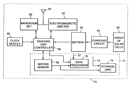
Fig. 2 shows in block diagram form an exemplary
embodiment of a mobile tracking unit 10 with an apparatus 9 for
detecting respective defective conditions associated with a set of
195 railway vehicle wheels and with the railtrack upon which a given
RD 23657
CA 02163629 2002-05-02
-9-
railway vehicle travels. It should be appreciated that although
apparatus 9 is shown in Fig. 2 as being operatively combined or
integrated with mobile tracking unit 10, such combination or
integration is only optional, being that apparatus 9 can easily be
s designed to function independently from mobile tracking unit 10.
The key advantages of the present invention are achieved by
employing a motion sensor 56, such as a low power
accelerometer, vibration sensor, shock sensor or combination
thereof for generating data indicative of motion at least along a
to generally vertical axis 28 (Figs. 1 and 3) relative to the railtrack.
For the purpose of optionally enhancing versatility of use, a set of
three accelerometers or motion sensors individually integrated
with suitable signal conditioning circuitry in a respective single
monolithic integrated circuit, such as accelerometer model
15 ADXL50 available from Analog Devices, Norwood, MA, or
similar accelerometers and motion sensors, can be conveniently
mounted in the vehicle or in the tracking unit to provide triaxial
sensing along three mutually orthogonal axes 28, 30 and 32 (Fig.
1) wherein one of the three axes is the generally vertical axis 28.
z o The vertical motion data and horizontal motion data measured
with such accelerometer or motion sensor set can be conveniently
used for various other purposes, such as for allowing electrical
power reduction under predetermined conditions, as described in
the aforementioned Canadian patent application, Serial No.
25 2,163,628. Rotational measurement data 72 indicative of rotational
rate w of the wheel set can be conveniently generated using any
PCT/US95I05620
WO 95131053 2 ~l 6~3 6 ~ 9
- lU -
one of various rotation measurement techniques. For example,
the rotational rate data can be generated with a suitable rotation
measurement unit 80 (Fig. 3A), such as a wheel rotation counter,
225 wheel tachometer and similar devices. Alternatively, the wheel
rotational rate data can be generated or computed by simply
dividing the railcar velocity (available from navigation set 50) by
the respective wheel set circumference. In each case, the
rotational rate data and the motion sensor data indicative of
230 motion at least along the generally vertical axis is supplied to a
data processor ?0 or suitably designed circuitry devoted to
assessing or detecting the presence of the foregoing respective
defective conditions. For example, the "flat wheel" and/or
damaged bearing condition is detected based on the rotational rate
235 data and motion data being supplied to processor 70. Similarly,
the railtrack or railbed defective condition can be determined
simply based on the motion data received by data processor ?0.
As should be apparent to those skilled in the art, the data
processing may include a variety of processing techniques such as
240 Fourier analysis, matched filtering, autocorrelation and
thresholding techniques and similar processing techniques.
Additional processing of the motion sensor data can conveniently
provide additional information about the railcar status such as the
loading status of the railcar. For example, measuring the
245 frequency of sway motion (i.e., sway or roll motion about the
longitudinal axis of the rail vehicle) and the vertical bounce
frequency of the railcar c:an provide substantially accurate
~O 95/31053 PCT/L1S95/05620
'~l ~'3
-"-
information regrading the loading status of the railcar. For
example, such information is useful for deternlining whether the
250 rail vehicle is being loaded beyond its maximum loading capacity.
Fig. 2 also shows that mobile tracking unit 10
includes a navigation set 50 capable of generating data
substantially corresponding to the vehicle position. The
navigation set is chosen depending on the particular navigation
255 system used for supplying navigation signals to a given mobile
tracking unit. Preferably, the navigation set is a GPS receiver
such as a multichannel receiver. However, it should be apparent
that other receivers designed for acquiring signals from a
corresponding navigation system can also be employed. For
260 example, the navigation set, depending on the vehicle position
accuracy requirements, can be chosen as a Loran-C receiver or
other such less highly-accurate navigation receiver than a GPS
receiver. Mobile tracking unit 10 may include a suitable
electromagnetic radiation emitter 52 functionally independent
265 from the navigation set. Emitter 52 is capable of at least
transmitting the vehicle position data by way of communication
link 14 (Fig. 1) to the control station. If a GPS receiver is used,
the GPS receiver and the emitter can be conveniently integrated
as a single integrated unit for maximizing efficiency of
270 installation and operation. An example of one such integrated
unit is the commercially available Galaxy Inmarsat-C/GPS
integrated unit available from Trimble Navigation, Sunnyvale,
WO 95131053 , PCT/US95/05620
- 12-
California which is conveniently designed for data communication
and position reporting between the control station and the mobile
275 tracking unit. A single, low profile antenna 54 can be
conveniently used for both GPS signal acquisition and satellite
communication. A tracking unit controller 58 can conveniently
provide for controlling operation of the various components in
the mobile tracking unit. The tracking unit controller may
280 comprise a conventional multi-bit single chip digital
microcontroller suitably programmed to control operation of
navigation set 50, emitter 52 and apparatus 9. A real-time clock
module 60 can be connected to tracking unit controller 58 so as to
periodically enable the controller to resume operation after the
285 controller is in a "sleep-mode" associated with a low power mode
of operation. Preferably, tracking unit controller 58 includes
sufficient memory and throughput capability to process data
acquired from additional sensing elements (not shown) in the
vehicle. A power source such as battery 62 is used to enable
290 operation of mobile tracking unit 10. As shown in Fig. 2, battery
62 can be a rechargeable battery, such as a nickel-cadmium
battery or a similar rechargeable battery, coupled to a suitable
charging circuit 64 which receives electrical power from an array
of solar cells 66 or other such electrical power transducer. The
295 charging circuitry typically includes suitable charging regulators
and voltage and current sensors (not shown) monitored by the
controller for determining the condition of the battery. A backup
battery (not shown) can be conveniently provi3ed to enhance
PCT/US95/05620
°-~rJO 95/31053
-13-
reliable operation of the mobile tracking unit. Alternatively,
300 battery 62 can be a nonrechargeable battery replaced at
preestablished time intervals. Those skilled in the art will
appreciate that the data from the motion sensor and rotation
measurement data 72 can be handled in a variety of ways. For
example, raw or unprocessed data can be stored in a storage unit
305 74 to be retrieved and processed at a later time. Conversely, such
raw data can be supplied via tracking unit controller 58 to
electromagnetic transmitter 52 so that such raw data be processed
by a suitable data processor at the remote control station 18 (Fig.
1), thus reducing the weight and electrical power consumption of
310 the mobile tracking unit. In either case, the apparatus of the
present invention, singly or in combination with a mobile
tracking unit, conveniently provides useful data indicative of
~spective defective conditions associated with railway vehicle
wheels and railtracks. It should be understood that in lieu of a
315 navigation set, such as a GPS or a LORAN receiver, other
alternative techniques can be used for determining, for example,
the location of a defective railtrack. For example, if the time at
which detection of such defective condition occurs is recorded,
then simply knowing the schedule of travel (i.e., the travel history
320 of the railway vehicle as a function of time) allows for estimating
the location of the railway vehicle when the defective railtrack
was detected (i.e., the location of the defective railtrack).
Alternatively, a wheel tachometer or similar device can be used to
count wheel revolutions under predetermined events. For
WO 95!31053 PCTIUS95/05620 -
- 14-
325 instance, counting the number of revolutions occurring from
detection of a damaged railtrack to a given destination point
allows for estimating the distance from the damaged railtrack to
such destination point (the distance is computed by multiplying
wheel circumference by the wheel rotation count). In this case,
330 by simply knowing the route travelled (and without time
information, i.e., travel schedule) allows for determining the
location of the defective railtrack. Thus, it should now be
apparent that use of a navigation set for determining the location
of a defective condition, such as the location of a bad railtrack, is
335 only optional in view of the above-described alternative
techniques.
It should be appreciated from Fig 3A that if the
wheel exhibits a defective region such as substantially flat region
24A, then motion sensor 56 will sense mechanical energy in a
340 frequency region substantially corresponding to the wheel
rotation frequency (i.e., wheel rotation rate w) and harmonics
thereof as measured in the wheel rotational rate data 72 from
rotational measurement unit 80. The data processor can be
readily designed to incorporate a digital signal processor module
345 comprising, by way of example and not of limitation, a discrete
Fourier processor 76 which processes the wheel rotational rate
data 73 and the motion sensor data so as to determine the
condition generally referred as "flat wheel" condition which can
be associated with at least one wheel of the wheel set. Although
°
-rv0 95/31053 PCT/US95/05620
-15-
350 Fig. 3A specifically depicts a defornlity associated with a "flat
wheel" condition, in a more general case, Fig. 3A can be used to
conceptualize other deformities such as can develop in the
bearings (not shown) which supports a wheel 24 that may not
have a flat region. As is generally known by those skilled in the
355 art, a respective wheel set comprises, for example, two wheels
which are rotatively coupled to the opposite ends of a rigid axle
by suitable bearings having balls or rollers confined between
outer and inner races. These bearings typically exhibit
predetermined mechanical characteristics as a function of wheel
360 rotation rate, i.e., a generally constant number of balls or rollers
passes over the top of the axle for each revolution since the top of
the axle is typically the region where the balls or rollers
experience maximum loading. It can be shown that when either
the outer or inner race (or the balls or rollers) are damaged, then
365 for a given wheel rotation rate, there is generation of respective
frequency components or beat frequencies predeterminedly
situated above and below the wheel rotation frequency. Processor
70 can readily be designed to detect such frequency components
in the same manner that such processor detects the "flat wheel"
370 condition. In each case, discrete Fourier processing module 76
can be integrated in a single integrated circuit chip or in a
processing module such as processing module TMS320 available
from Texas Instruments.
W0 95/31053 PCT/US95/05620 -
- 16-
Fig. 3B shows that when the railway vehicle passes
375 over a railtrack 26 that has a portion 26A that substantially sags
or drops under the weight of the railway vehicle, then motion
sensor 56 will sense mechanical energy having a predetermined
signature which characterizes such undesirable railtrack
condition. It should be appreciated that the mechanical energy
380 signature corresponding to a given defective track condition is
generally independent from the wheel rotation rate and, hence,
for the purpose of determining a defective railtrack condition,
rotational rate data 72 (Fig. 3A) is not necessary.
Fig. 4A is an exemplary simulation plot of a typical
385 vertical accelerometer output signal in the time domain in the
absence of a defective condition, that is, the railway vehicle
wheels and/or bearings are substantially undeformed and the
railtrack does not exhibit any significant drop or sag under the
weight of the railway vehicle. Fig. 4B is the power spectral
390 density in the frequency domain for the accelerometer output
signal corresponding to the condition shown in Fig. 4A.
Fig. SA is an exemplary simulation plot of a typical
vertical accelerometer output signal in the time domain when
sensing a "flat wheel" condition. Those skilled in the art will
395 appreciate that the periodicity of the impulse-like spikes seen in
Fig. SA directly correspond to the wheel rate rotation to. Fig. SB
shows the power spectral density in the frequency domain for the
~v 0 95/31053 . PCT/US95/05620
21 ~3" 6
2~
accelerometer output signal corresponding to the condition shown
in Fig. SA. It is seen that the periodic impulse-Iike spikes in the
400 frequency domain reveal the presence of the "flat wheel"
condition. This exemplary power spectral density was obtained
using a conventional unwindowed Fourier transform processing
technique. As previously suggested, other processing techniques
in lieu of a Fourier transform can be effectively used to detect the
405 presence of a "flat wheel" condition.
Fig. 6A is an exemplary simulation plot of a typical
vertical accelerometer output signal when sensing both a "flat
wheel" condition characterized by the impulse-like spikes and a
defective railtrack condition characterized by the down-up
410 waveshape. Fig. 6B shows the power spectral density in the
frequency domain for the accelerometer output signal shown in
Fig. 6A. Again, it is seen that the periodic impulse-like spikes in
the frequency domain reveal the presence of the "flat wheel"
condition. Further, the railtrack defective condition, i.e., the
415 railtrack sag or drop, is revealed in the frequency domain by the
dramatic relative increase in the low frequency components.
A method for detecting defective conditions
associated with a set of railway vehicle wheels and with a
railtrack upon which a given railway vehicle travels comprises
420 the steps of generating data indicative of rotational rate of the set
of wheels; generating data indicative of motion at least along a
generally vertical axis relative to the railtrack; processing the
WO 95/31053 PCTIUS95I05620
2163
- is -
rotational rate and motion data for detection of a defective
condition associated with at least one wheel of the wheel set; and
425 processing the motion data for detection of a defective condition
associated with at least a portion of the railtrack. The additional
step of generating data substantially corresponding to a respective
railway vehicle position conveniently allows for substantially
determining the location at which any respective defective
430 condition occurs. This is especially useful in the case of
establishing the location of a defective railtrack portion over a
known route. One simple way to determine the location of such
defect is counting the number of wheel revolutions upon detection
of the defective railtrack portion; and then measuring distance
435 traveled over the known route from a current railway vehicle
location (e.g., any destination of the railway vehicle over the
known route). The distance traveled over the known route upon
detection of the defective railtrack portion is simply calculated by
multiplying the wheel revolution count by the wheel set
440 circumference. This conveniently allows for substantially and
economically determining the location of the defective railtrack
portion over the known route at least with respect to the current
railway vehicle location.
While only certain features of the invention have
445 been illustrated and described herein, many modifications,
substitutions, changes, and equivalents will now occur to those
skilled in the art. It is, therefore, to be understood that the
""~WO 95131053 216 3 62 ~ PCTIUS95/05620
-19-
appended claims are intended to cover all such modifications and
changes as fall within the true spirit of the invention.