Note : Les descriptions sont présentées dans la langue officielle dans laquelle elles ont été soumises.
WO 95/01831 PCT/FI94/00304
1
METHOD FOR POLYMERIZING OLEFINS IN A Ft,ttTn-B~:D REACTOR.
The invention relates to a method of polymerizing and copolymerizing olefins
in a
fluidized-bed reactor suited for the polymerization of olefins in gas phase
and
equipped with a stirrer.
Gas-phase polymerization of olefins is conventionally performed in a fluidized
bed, where the polymerization reaction occurs in a bed comprised of particles
formed during polymerization. The heat generated in the polymerization is
removed by circulating through the reactor and the fluidized bed such a
circulating
gas that, besides the monomers to be polymerized, also frequently contains
hydrogen, inert diluents or inert gases. The circulating gas is cooled in a
cooler
placed outside the reactor and is then passed back to the lower part of the
reactor.
The circulating gas rising through the reactor keeps the fluidized bed in
fluidized
~5 state maintaining efficient stirring in the bed. The larger the reactor,
the more
difficult it is to maintain homogeneous fluidization and stirring throughout
the
entire volume of the fluidized bed. In fact, it has been found that
particularly the
lower corners of the reaction space may contain zones with insufficient
fluidization and stirring, which causes inferior heat transfer. This in turn
may
2o cause local overheating, whereby the temperature of the polymer particles
reaches
the softening point thus initiating the growth of adhering agglomerated clumps
which then stick to the reactor walls. When such agglomerated polymer clumps
later detach from the reactor walls, they deteriorate the quality of the
product.
25 Remedy to the above-described problem in fluidized-bed reactors has been
attempted through complementing the reactor with different types of mechanical
agitator elements which augment the stirring action. A typical agitator device
used
is an anchor agitator having a pair or greater number of support arms attached
to a
vertical drive shaft with the ends of the arms carrying vertically aligned
agitator
3o blades at equal distances from the vertical drive shaft. A disadvantage of
such a
stirrer is that the polymer particles driven by the centrifugal force imposed
by the
CA 02166486 2004-03-02
30320-3
2
stirrer tend to travel toward the inside surface of the
walls of the reactor. Consequently, agglomerated polymer
clumps begin to adhere to the reactor walls. If the
agitator arms are relatively short, a vortex is
simultaneously induced in the center zone of the reactor,
whereby the circulating gas introduced to the lower part of
the reactor preferentially seeks toward this vortex zone. A
solution to this problem has been attempted through
providing the stirrer with a number of agitator arms of
difference lengths.
US patent 4,366,123 discloses an anchor agitator
with the main agitator arms designed so long that the
agitator blades attached to the ends of the arms move very
close to the vertical inside surface wall of the reactor.
Additionally, the agitator has shorter agitator arms
carrying agitator blades that move closer to the drive
shaft. Furthermore, at least the main agitator blades have
a triangular cross section. This design aims at achieving a
sufficient stirring efficiency and avoiding vibration
effects induced by the rotational movement of the agitator.
US patent 4,188,132 discloses a spiral stirrer of
a fluidized bed reactor comprising the stirrer attached to
the end of a drive shaft only at the lower part of the
spiral stirrer which at its lower end over the length of the
first turn of the spiral is provided with a separate
distributor spiral element. Fresh gas acting as a cooling
medium is introduced to the reactor via an inlet channel of
the drive shaft. The purpose of said distribution spiral
element is to reverse the direction of the gas flow entering
the reactor and thus prevent the formation of agglomerated
clumps on the bottom of the reactor.
CA 02166486 2004-03-02
30320-3
3
However, the above-cited US patents fail to cure
the insufficient fluidization at the reactor corners and
inside surface of the walls and the adherence of the polymer
particles to the inside surface of the walls of the reactor,
which typically occur in large-diameter reactors. The
present invention is especially related to the elimination
of these problems.
SUMMARY OF THE INVENTION
The method according to the present invention
achieves simultaneously both an efficient stirring action
and improvement of fluidization in the critical zones and
prevention of polymer particle adherence to the reactor
inner surfaces. Hence, the invention is related to a method
of polymerizing olefins in a fluidized-bed polymerization
reactor in which olefin monomers are polymerized in a
fluidized bed formed by polymerizing particles containing
the polymerization catalyst, said fluidized bed being
maintained in fluidized state by introducing to the reactor
at least one circulating gas flow containing polymerizable
monomers and optionally hydrogen, inert gases or a diluent
gas, and said fluidized bed being stirred by virtue of at
least one agitator means which is attached to an essentially
vertical drive shaft and is suited for stirring a fluidized
bed. The method according to the invention is characterized
in that at least a portion of the gas flow introduced to the
reactor is passed to the reactor via at least one flow
channel provided to the inside of said shaft and said
agitator means and extending close to the reactor wall.
Accordingly, in the method according to the
invention is employed a flow channel via which a gaseous
medium can be passed at a high velocity directly to such
reactor vessel zones where the action of the conventional
CA 02166486 2004-03-02
30320-3
4
fluidizing gas flow is weakest. In this fashion a flushing
action is achieved that significantly reduces the
agglomeration and adherence of polymer particles to the
lower edge and inside surface of walls of the reactor vessel
bottom part.
According to a preferred embodiment of the
invention, the stirrer drive shaft, agitator arms attached
to said mixer drive shaft and agitator blades connected to
said arms are hollow and form a continuous flow channel via
which the stirring gas can be introduced to the reactor
through holes of the agitator blades. The gas ejected from
the holes flushes the reactor walls and improves the
fluidization and the stirring of the particles contained in
the bed, simultaneously improving cooling in such zones
where overheating otherwise occurs readily.
The agitator blades are advantageously, whilst not
necessarily, vertically extending paddles connected to the
agitator arms attached to the drive shaft of the stirrer.
The agitator arms are advantageously, whilst not
necessarily, horizontally extending arms with a freely
selectable cross section. However, as a rule the cross
section of the arms is designed for minimum agitation
resistance. The length of the agitator arms is
advantageously designed such that permits the agitator
blades connected to the ends of the agitator arms to extend
as close as possible to the inside surface of the walls of
the reactor vessel where the fluidization action is
inherently weakest.
According to a further embodiment of the invention
described herein a method is provided wherein said portion
of the gas flow is passed to the reactor via at least one
horizontal agitator arms and agitator blades attached to the
CA 02166486 2004-03-02
30320-3
end thereof, said agitator blades being adapted to reach
close to the reactor wall.
According to an embodiment of the invention, the
stirrer may include at least one auxiliary arm with agitator
5 blades, whereby the length of the auxiliary arm may be
shorter than that of the main agitator arm. Also here the
auxiliary arm and the agitator blades attached thereto may
be hollow so as to form a flow channel for the introduction
of the stirring gas to the reactor. Typically, a pair of
auxiliary arms is sufficient to achieve a satisfactory
stirring effect.
The gaseous medium passed via the stirrer can be
any of the gases normally introduced to the reactor.
Accordingly, the desired action can be attained by using the
monomer or comonomer feedstock, hydrogen, an inert gas or
inert gaseous diluents in combination or separately as the
stirring gas. The stirring gas flow passed via the stirrer
may also comprise a side stream taken from the circulating
gas flow passed through the reactor. Since the circulating
gas may, however, contain fine polymer particles escaped via
the reactor top, the stirring gas passed via the stirrer is
advantageously a catalyst- and polymer-free gas formed by,
e.g., an inert medium, monomers or mixtures thereof.
The proportion of the gaseous medium passed via
the stirrer can be varied in the range of 0.1-30 wt-%. The
actual proportion of the stirring gas sufficient for
attaining a satisfactory flushing effect may, however, be
selected appreciably lower than the upper limit given above,
whereby the amount of the stirring gas typically is
0.1-10 wt-%, advantageously 0.3-5 wt-%, of the total gas
flow introduced to the reactor. Given the volumes of
CA 02166486 2004-03-02
30320-3
6
industrial-scale fluidized-bed reactors, cited proportions
correspond to stirring gas flows of several tons per hour.
A polymerization reactor equipped with a stirrer
according to the invention can be used for gas-phase
fluidized-bed polymerization or copolymerization of any
polymerizable monomer. Suitable monomers are, e.g., olefins
such as ethene, propene, butene, pentenes, hexenes, etc.,
and any other monomers.
BRIEF DESCRIPTION OF THE DRAWINGS
The invention is next examined with reference to
annexed drawings in which:
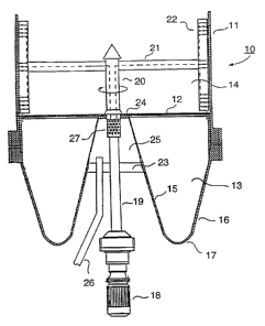
Fig. 1 is a sectional side view of the bottom of a
fluidized-bed reactor equipped with a stirrer designed to
implement the method according to the invention; and
Fig. 2 is cross-sectional view of an agitator
blade of a stirrer according to the invention.
DETAILED DESCRIPTION OF THE PREFERRED EMBODIMENTS
With reference to Fig. 1, the fluidized-bed
reactor is denoted by a general reference numeral 10. The
reactor vessel has a cylindrical outer wall 11. A
perforated gas distribution plate 12 divides the reactor 10
into an infeed portion 13 of the circulating gas and a
fluidized-bed portion 14. The bottom part of the reactor 10
is comprised of two concentric conical shaped surfaces of
revolution, having an inner wall surface 15 and an outer
wall surface 16. Surfaces 15 and 16 are joined to each
other by a smooth annular section 17 which forms the
lowermost part of the reactor vessel bottom. The wall
section formed by the inner surface 15 is shaped at its
upper rim into a horizontal support plane 24.
CA 02166486 2004-03-02
30320-3
7
The circulating gas flow is passed to the infeed
portion 13 of the reactor 10 via at least one circulating
gas pipe (not shown) and further via the gas sparger
plate 12 to the fluidized-bed portion 14.
According to the invention, the stirrer comprises
an electric motor 18 rotating a vertical connecting shaft 19
which further extends into the reactor as a stirrer drive
shaft 20 having agitator arms 21 attached to it with
agitator blades 22 connected to the arm ends. The electric
motor 18 with its bearings for rotating the stirrer drive
shaft 20 is advantageously sited within or under the bell-
shaped recess formed by the inner wall surface 15 of the
reactor bottom. The shaft 19 is advantageously taken by
means of a rotary seal through a horizontal auxiliary
wall 23, whereby the auxiliary wall 23, the inner wall
surface 15 and the horizontal support plane 24 together
enclose an infeed chamber 25 for the feed of the stirring
gas. By mounting the shaft 19 and the stirrer drive
shaft 20 in bearings on the auxiliary wall 23 and the
horizontal support plane 24, a rigid support is
advantageously provided for the shafts, and by the same
token, the gas sparger plate 12 can be supported to the
horizontal support plane 24.
The method according to the invention employs a
stirrer having a hollow connecting shaft 20 through which
gaseous or liquid substances can be passed. Similarly, the
agitator arm 21 is made hollow and its hollow inner channel
communicates with the hollow inner channel of the mixer
drive shaft 20. Furthermore, the agitator blades 22 are
made hollow and their hollow inner cavities are adapted to
communicate with the inner hollow channel of the agitator
arm 21. Hence, a continuous channel is formed extending
from the stirrer drive shaft 20 to the agitator blades 22.
CA 02166486 2004-03-02
30320-3
8
The gaseous medium is passed to the stirrer
advantageously via a chamber 25. The gas is first passed
via a pipe 26 to the chamber 25 and therefrom further via an
optional strainer 27 into the hollow stirrer drive shaft 20.
The gas pumped to the stirrer may comprise a side stream
taken from the circulating gas flow passed to the bottom
part of the reactor 10, whilst more advantageously the
stirring gas is fresh catalyst- and polymer-free gas such as
a monomer, comonomer, hydrogen or an inert medium.
With reference to Fig. 2, the agitator blades 22
are provided with flow openings (ejection holes) 28 via
which the stirring gases can be introduced to the
reactor 10. The flow openings 28 may comprise, e.g.,
perforated holes which may be made to the entire length of
the agitator blade 22, or alternatively, only over a portion
thereof. According to the invention described herein, the
gas flow is passed to the reactor 10 via ejection holes (28)
drilled to agitator blades 22.
Whilst the method according to the invention is
herein described applied to the use of a combination of
horizontal agitator arms with vertically aligned agitator
blades, the stirrer may equally well comprise a spirally-
shaped hollow agitator element in which the outer edge of
the spiral is provided with perforation for ejecting the
stirring gas.