Sélection de la langue

Search

Sommaire du brevet 2166978 

Énoncé de désistement de responsabilité concernant l'information provenant de tiers

Une partie des informations de ce site Web a été fournie par des sources externes. Le gouvernement du Canada n'assume aucune responsabilité concernant la précision, l'actualité ou la fiabilité des informations fournies par les sources externes. Les utilisateurs qui désirent employer cette information devraient consulter directement la source des informations. Le contenu fourni par les sources externes n'est pas assujetti aux exigences sur les langues officielles, la protection des renseignements personnels et l'accessibilité.

Disponibilité de l'Abrégé et des Revendications

L'apparition de différences dans le texte et l'image des Revendications et de l'Abrégé dépend du moment auquel le document est publié. Les textes des Revendications et de l'Abrégé sont affichés :

  • lorsque la demande peut être examinée par le public;
  • lorsque le brevet est émis (délivrance).
(12) Demande de brevet: (11) CA 2166978
(54) Titre français: PILES A COMBUSTIBLE
(54) Titre anglais: FUEL CELLS
Statut: Morte
Données bibliographiques
(51) Classification internationale des brevets (CIB):
  • G01N 27/26 (2006.01)
  • G01N 27/403 (2006.01)
  • G01N 27/49 (2006.01)
  • H01M 8/00 (2006.01)
(72) Inventeurs :
  • CRIDDLE, WILLIAM JAMES (Royaume-Uni)
  • HANSEN, NEILS RICHARD STEWART (Royaume-Uni)
(73) Titulaires :
  • LION LABORATORIES PLC (Royaume-Uni)
(71) Demandeurs :
(74) Agent: OSLER, HOSKIN & HARCOURT LLP
(74) Co-agent:
(45) Délivré:
(86) Date de dépôt PCT: 1994-07-08
(87) Mise à la disponibilité du public: 1995-01-26
Licence disponible: S.O.
(25) Langue des documents déposés: Anglais

Traité de coopération en matière de brevets (PCT): Oui
(86) Numéro de la demande PCT: PCT/GB1994/001489
(87) Numéro de publication internationale PCT: WO1995/002817
(85) Entrée nationale: 1996-01-10

(30) Données de priorité de la demande:
Numéro de la demande Pays / territoire Date
9314609.0 Royaume-Uni 1993-07-14
9315388.0 Royaume-Uni 1993-07-24

Abrégés

Abrégé français

Sonde (10) de cellule électrochimique comprenant un corps principal (11) dans lequel sont montés des électrodes actives (12), des contre-électrodes (13) et des contacts respectifs (14 à 17). Les électrodes actives (12) sont montées l'une en face de l'autre de manière à définir entre elles un espace pour les échantillons. Les électrodes (12) sont électriquement interconnectées en parallèle comme les deux contre-électrodes (13). Cette configuration avantageuse assure une très grande aire de surface à l'électrode active pour un espace (22) d'un faible volume pour les échantillons.


Abrégé anglais


A fuel cell sensor (10) comprises a main body (11) in which are mounted working electrodes (12), counter electrodes (13) and
respective contacts (14 to 17). The working electrodes (12) are mounted facing each other to define a sample space between them. The
electrodes (12) are electrically interconnected in parallel as are the two counter electrodes (13). This arrangement makes it possible to
provide a very large working electrode surface area for a small volume sample space (22).

Revendications

Note : Les revendications sont présentées dans la langue officielle dans laquelle elles ont été soumises.


6

Claims
1. A fuel cell for detecting oxidisable fuel components in
a gas or vapour including a pair of working electrodes
facing each other to define a sample receiving space between
them.
2. A fuel cell as claimed in Claim 1, wherein the working
electrodes are electrically connected.
3. A fuel cell as claimed in Claim 1 or claims further
including a counter electrode for each working electrode.
4. A fuel cell as claimed in Claim 3, wherein the counter
electrodes are electrically connected.
5. A fuel cell as claimed in Claim 3 or Claim 4, wherein
the sets of electrodes are connected in parallel or in
series.
60 A fuel cell as claimed in any one of Claim 3 to Claim
5, wherein the electrodes in each working counter electrode
pair are separated by an electrolytically impregnated body.
7. A fuel cell as claimed in any one of the preceding
Claims, wherein the spacing between the working electrodes
is between 0.5mm and 5mm.
8. A fuel cell as claimed in Claim 7, wherein the spacing
is between 1mm and 2mm.
9. A fuel cell as claimed in any one of the preceding
Claims, wherein the net load for the sensor is approximately
equal to 10.OMEGA..
10. A fuel cell as claimed in any one of Claims 1 to 8,
wherein the fuel cell includes a load resistor across its
output which is approximately equal to its impedance.

7

11. A fuel cell as claimed in any one of the preceding
Claims, having a closed loop electrical contact for at least
one of its electrodes, the loop being substantially
circumjacent the operative surface of the electrode.
12. A fuel cell having a closed loop electrical contact for
at least one of its electrodes, the loop being substantially
circumjacent the operative surface of the electrode.


Description

Note : Les descriptions sont présentées dans la langue officielle dans laquelle elles ont été soumises.

WO g5/02817 2 ~
~ PCT/GB94/01~9


Fuel Cells


This invention relates to fuel cells and in particular,
but not exclusively, such cells which act as sensors for
oxidisable components in gases.
Fuel cells were first invented by Sir William Grove in
1839 and in recent years have been used in many arrangements
for the detecting of oxidisable components of gases or
vapours, for example in breath testing equipment.
Essentially the fuel cell comprises a working electrode or
anode and a counter electrode or cathode which are separated
by an electrolyte, usually by a porous disc impregnated with
an acidic electrolyte. The electrochemical oxidation of the
fuel component in the gas results in the development o~ an
electrical potential difference resulting in a flow of
electrons from the anode to the cathode and this current
and/or potential difference can be detected. One such fuel
cell is made by Lion Laboratories Plc.
Although these fuel cells have been successful in a

limited field, considerable problems have been experienced
both in the time taken for the fuel cell to consume the
oxidisable component in the sample and in the time taken for
the cell to clear so that it is ready to sense a further
sample.
From one aspect of the invention there is provided a
sensor for detecting oxidisable fuel components in a gas or
vapour including a pair of working electrodes facing each
other to define a sample receiving space between them.


WO95~U2817 PCT/GB94/01489
2~6~7g

This arrangement of facing working electrodes
substantially increases the surface area of the working
electrode for a given cross-sectional dimension and hence
significantly reduces the time taken for a fuel component to
contact and hence react with the working electrode. It
further enables the working electrodes to be placed very
close to one another hence reducing the length of the mean
free path available to any fuel component molecule injected
into the sample space before it strikes a working electrode.
In traditional designs there can be a significant dead space
above the single working electrode.
In a preferred embodiment the working electrodes are
electrically connected. Further it is preferred that there
is a counter electrode for each working electrode and they
will be separated from each other by a suitable
electrolytically impregnated body. The counter electrodes
should also be electrically connected, when this is true of
the working electrodes. The respective sets of electrodes
can be connected in parallel or in series. In the former
arrangement the electrodes could be viewed as being a single
cell in a bent configuration, and such an arrangement is
included in the invention and indeed other wrapped around
arrangements may be possible although these may introduce
constructional complexities which limit the closest approach
of the two working electrode sections.
Preferably the spacing between the working electrodes
is between 0.5mm and 5mm and a spacing of lmm to 2mm has
been found to be a good compromise between cell efficiency


wo gS/02817 ~ 9 ~ ~ PCT/GB94/01~9
. .
.~ . .


and constructional simplicity.
The rate of clearing of the cell may be a function of
the net load and it has been found convenient to have a net
load of approximately 10 ohms. The sensor may thus have a
load resistor across its output which is approximately equal
to its impedance.
From another aspect the invention consists in a fuel
cell having a closed loop electrical contact for at least
one of its electrodes, the loop being substantially
circumjacent the operative surface of the electrode.
Traditionally single wire contacts have been used and
these can cause local resistance problems and manufacturing
difficulties. The use of a closed loop, and preferably
annular, contact ensures that there is electrical contact
between the electrode and the contact at at least some parts
of the contact and removes many localised affects.
The invention also consists in a sensor as described
above with the closed loop contact set out above.
~ lthough the invention has been defined above it
is to be understood that it includes any inventive
combination of the features set out above or in the
following description.
The invention may be performed in various ways and a
specific embodiment will now be described by way of example,
with reference to the accompanying drawings, in which:
Figure 1 is an exploded view of one version of a sensor
according to the invention;
Figure 2 is a diagrammatic vertical cross-sectional

~i :
WO95/02817 PCT/GB94/01489
2 ~ 7 8


view of the electrodes of the fuel cell illustrating their
electrical connections; and
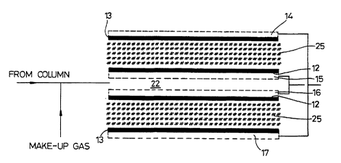
Figure 3 is the same as Figure 2, but shows an
alternative arrangement of electrical connections.
A fuel cell sensor lO comprises a main body 11 in which
are mounted working electrodes 12, counter electrodes 13 and
respective contacts 14 to 17. The main body is closed off
by a top cover 18 and a bottom cover 19 and sealed by
respective O rings 20 and 21.
The working electrodes 12 are mounted facing each other
to define a sample space 22 between them and a sample inlet
23 debouches into this space and in outlet 24 is also
connected into it. Each of the electrodes 12,13 comprises
a platinum black layer on a micro-porous PVC body and the
two bodies 25 in each working/counter electrode pair
together contain an acidic electrolyte such as H2SO4.
As can be seen from Figure 2 the two working electrodes
12 are electrically interconnected in parallel, as are the
two counter electrodes 13. These connections take place
through the respective contacts 15 to 17 which are each in
the form of gold plated stainless steel annulus which
extends around the peripheral margin of its respective
electrode.
As has been explained above this configuration allows
the working electrodes 12 to be brought very close to each
other so that the sample space 22 has a very small volume
but a very large working electrode surface area. This
results in a sensor which is extremely sensitive, fast to

WO9S/0~17 21 6 ~ 9 7 ~ PCT/GB94/01489


react and which can also clear rapidly.
These characteristics not only mean that a highly
sensitive fuel cell is available for traditional existing
uses, but also that it can be used for less common purposes
such as in gas chromatography (as for example shown in
Figure 2). In that case the cell is designed to perform
best with a carrier or make up gas flow through the cell;
the sample gas being introduced into this flow. Preferably
the make up gas has a 50%-60% relative humidity to prevent
drying out of the cell and conveniently it may be nitrogen.
As previously stated, the electrode pairs are connected
in parallel and this configuration maximises the current
generated.
` An alternative series connection is shown in Figure 3.
This arrangement minimises current but maximises the
electrical potential of the cell. The configuration chosen
would then depend on whether the cell is to be used in
either a voltage or current measuring device.


Dessin représentatif
Une figure unique qui représente un dessin illustrant l'invention.
États administratifs

Pour une meilleure compréhension de l'état de la demande ou brevet qui figure sur cette page, la rubrique Mise en garde , et les descriptions de Brevet , États administratifs , Taxes périodiques et Historique des paiements devraient être consultées.

États administratifs

Titre Date
Date de délivrance prévu Non disponible
(86) Date de dépôt PCT 1994-07-08
(87) Date de publication PCT 1995-01-26
(85) Entrée nationale 1996-01-10
Demande morte 2001-07-09

Historique d'abandonnement

Date d'abandonnement Raison Reinstatement Date
2000-07-10 Taxe périodique sur la demande impayée

Historique des paiements

Type de taxes Anniversaire Échéance Montant payé Date payée
Le dépôt d'une demande de brevet 0,00 $ 1996-01-10
Taxe de maintien en état - Demande - nouvelle loi 2 1996-07-08 100,00 $ 1996-07-03
Enregistrement de documents 0,00 $ 1996-09-19
Taxe de maintien en état - Demande - nouvelle loi 3 1997-07-08 100,00 $ 1997-07-04
Taxe de maintien en état - Demande - nouvelle loi 4 1998-07-08 100,00 $ 1998-06-30
Taxe de maintien en état - Demande - nouvelle loi 5 1999-07-08 150,00 $ 1999-07-07
Titulaires au dossier

Les titulaires actuels et antérieures au dossier sont affichés en ordre alphabétique.

Titulaires actuels au dossier
LION LABORATORIES PLC
Titulaires antérieures au dossier
CRIDDLE, WILLIAM JAMES
HANSEN, NEILS RICHARD STEWART
Les propriétaires antérieurs qui ne figurent pas dans la liste des « Propriétaires au dossier » apparaîtront dans d'autres documents au dossier.
Documents

Pour visionner les fichiers sélectionnés, entrer le code reCAPTCHA :


Pour visualiser une image, cliquer sur un lien dans la colonne description du document. Pour télécharger l'image (les images), cliquer l'une ou plusieurs cases à cocher dans la première colonne et ensuite cliquer sur le bouton "Télécharger sélection en format PDF (archive Zip)" ou le bouton "Télécharger sélection (en un fichier PDF fusionné)".

Liste des documents de brevet publiés et non publiés sur la BDBC .

Si vous avez des difficultés à accéder au contenu, veuillez communiquer avec le Centre de services à la clientèle au 1-866-997-1936, ou envoyer un courriel au Centre de service à la clientèle de l'OPIC.


Description du
Document 
Date
(yyyy-mm-dd) 
Nombre de pages   Taille de l'image (Ko) 
Abrégé 1995-01-26 1 53
Description 1995-01-26 5 191
Page couverture 1996-05-14 1 16
Revendications 1995-01-26 2 48
Dessins 1995-01-26 3 83
Dessins représentatifs 1997-06-12 1 15
Taxes 1999-07-07 1 55
Taxes 1998-06-30 1 57
Taxes 1997-07-04 1 50
Rapport d'examen préliminaire international 1996-01-10 13 361
Lettre du bureau 1996-02-13 1 21
Taxes 1996-07-03 1 53