Sélection de la langue

Search

Sommaire du brevet 2168493 

Énoncé de désistement de responsabilité concernant l'information provenant de tiers

Une partie des informations de ce site Web a été fournie par des sources externes. Le gouvernement du Canada n'assume aucune responsabilité concernant la précision, l'actualité ou la fiabilité des informations fournies par les sources externes. Les utilisateurs qui désirent employer cette information devraient consulter directement la source des informations. Le contenu fourni par les sources externes n'est pas assujetti aux exigences sur les langues officielles, la protection des renseignements personnels et l'accessibilité.

Disponibilité de l'Abrégé et des Revendications

L'apparition de différences dans le texte et l'image des Revendications et de l'Abrégé dépend du moment auquel le document est publié. Les textes des Revendications et de l'Abrégé sont affichés :

  • lorsque la demande peut être examinée par le public;
  • lorsque le brevet est émis (délivrance).
(12) Brevet: (11) CA 2168493
(54) Titre français: VENTILATION D'AVANT-TOIT
(54) Titre anglais: EAVE VENT
Statut: Périmé
Données bibliographiques
(51) Classification internationale des brevets (CIB):
  • E04D 13/17 (2006.01)
  • E04D 13/152 (2006.01)
  • F24F 7/02 (2006.01)
  • F24F 13/08 (2006.01)
(72) Inventeurs :
  • ANDERSON, CHARLES B. (Etats-Unis d'Amérique)
  • KENRICK, CHARLES R. (Etats-Unis d'Amérique)
(73) Titulaires :
  • BUILDER'S BEST, INC. (Etats-Unis d'Amérique)
(71) Demandeurs :
  • BUILDER'S BEST, INC. (Etats-Unis d'Amérique)
(74) Agent: BORDEN LADNER GERVAIS LLP
(74) Co-agent:
(45) Délivré: 2001-06-12
(22) Date de dépôt: 1996-01-31
(41) Mise à la disponibilité du public: 1996-08-22
Requête d'examen: 1997-12-10
Licence disponible: S.O.
(25) Langue des documents déposés: Anglais

Traité de coopération en matière de brevets (PCT): Non

(30) Données de priorité de la demande:
Numéro de la demande Pays / territoire Date
08/391,539 Etats-Unis d'Amérique 1995-02-21

Abrégés

Abrégé français

Une ventilation d'avant-toit pour évacuer des gaz d'une habitation, comprenant un boîtier présentant un bord de montage périphérique horizontal ayant des ouvertures pour recevoir un élément de fixation à cet égard, et définissant une sortie de débit d'air provenant du boîtier, une paroi verticale perpendiculaire au bord et présentant une partie supérieure, un raccord de tuyau s'étendant à partir de la paroi verticale et définissant une entrée de débit de gaz sur le boîtier, une paroi diagonale présentant une jointure avec et à un angle d'environ 45.degrés. par rapport à la partie supérieure de la paroi verticale, au bord horizontal, et deux parois d'extrémités opposées triangulaires joignant la paroi verticale, le bord horizontal et la paroi diagonale pour envelopper le boîtier, et un clapet de fermeture rectangulaire monté de façon pivotante sur un axe horizontal à la jointure, dépendant de la sortie de débit d'air, du pivotement à l'encontre de la paroi diagonale avec un débit d'air de sortie sortant pour une position d'affleurement contre la paroi diagonale, et du pivotement à l'encontre de la paroi verticale sous un débit d'air inversé.


Abrégé anglais

An eave vent for discharge of gases from a dwelling, comprising a housing havinga lower horizontal peripheral mounting rim having fa stener receiving openings therein, and defining an air flow outlet from the housing, a vertical wall normal to the rim and having a top portion, a hose connector extending from the vertical wall and defining a gas flow inlet to the housing, a diagonal wall having a juncture with and at an angle of about 45° to the vertical wall top portion, to the horizontal rim, and a pair of triangular opposite end walls joining the vertical wall, the horizontal rim and the diagonal wall to enclose the housing, and a rectangular closure flapper pivotally mounted on a horizontal axis at the juncture, depending over the air flow outlet, pivotal out against the diagonal wall with air flow out the outlet to lie flush against the diagonal wall, and pivotal against the vertical wall under reverse air flow.

Revendications

Note : Les revendications sont présentées dans la langue officielle dans laquelle elles ont été soumises.


The embodiments of the invention in which an exclusive property or privilege is
claimed are defined as follows.

-1-

An eave vent for discharge of gases from a dwelling, comprising:
a housing having a lower horizontal peripheral mounting rim having fastener
receiving openings therein, and defining an air flow outlet from said housing, a vertical
wall normal to said rim and having a top portion, a hose connector extending from said
vertical wall and defining a gas flow inlet to said housing, a diagonal wall having a
juncture with and extending from said vertical wall top portion to said horizontal rim, and
a pair of triangular opposite end walls joining said vertical wall, said horizontal rim and
said diagonal wall to enclose said housing; and
a closure flapper pivotally mounted on a horizontal pivot axis at said juncture,depending over said air flow outlet, and pivotal out against said diagonal wall with air
flow out said outlet.

2. The eave vent in claim 1 wherein said pivot axis is immediately adjacent saiddiagonal wall such that said flapper will lie flush against said diagonal wall with air flow
out said outlet.

3. The eave vent in claim 1 wherein said inlet is circular and said flapper is
rectangular.

4. The eave vent in claim 1 wherein said diagonal wall is at an angle of about 45° to
said vertical wall.

5. The eave vent in claim 4 wherein said angle is at least about 45°.

-5-

Description

Note : Les descriptions sont présentées dans la langue officielle dans laquelle elles ont été soumises.

2168~
EAVE VENT
BACKGROUND OF THE INVENTION
This invention relates to eave vents for housing, and particularly to an eave vent
for mounting in the horizontal eave of a dwelling, for discharge of vented gas such as air
from a clothes dryer, exhaust gas from a gas heater or furnace, or the like.
Vents for appliances such as clothes dryers usually are of the type that extend
through the vertical side wall of the house or apartment dwelling, with a hood on the
exterior and a vertical flapper inside the hood to prevent reverse air flow. There are
known difficulties with this arrangement. Specifically, forced air or other gas flowing
down out of the hood tends to cling to the dwelling side wall due to the Bernoulli effect,
llltim~tely striking the ground and leve~ g to create a back pressure on the vent. This
tends to prevent effective flow. Tn~t~ tion instructions typically advise to allow a certain
t~nre between the vent hood and the ground to lessen this action, but still a reverse
flow effect is noted. Also, there is normally created a negative gas ples~ure zone at a
location down the wall some di~t~n~e from the vent so that lint and other debris in the
ah~Ll.,~ll or disturbed from the ground gets deposited on the wall in an unsightly manner.
An all~ live to this type of vent is a roof jack where the gas is con-lucted up
through the rooftop. That type of structure, however, involves ullwallled added structural
alterations, leak potential, etc.
SUMMARY OF THE INVENTION
An object of this invention is to provide an eave vent for appliances such as
clothes dryers, gas heaters and the like, cor~lgurated such that when installed the
discharged gas is immediately removed from the vicinity of the dwelling wall. The
device employs the Bernoulli effect advantageously, along the underside of the horizontal
eave, to discharge the ejected gas in a fashion avoiding creation of backdraft ples~ule on
the vent, preventing debris collection on the side wall, and yet being relatively simple and
low cost to m~nllf~ctllre, and easy to install.
The eave vent has a housing with a lower horizontal peripheral mounting rim
having fastener receiving orifices, and defining a gas flow outlet, a vertical wall normal
to the rim and having a top portion, a hose connector exten-ling from the vertical wall and
defining a gas flow inlet, a diagonal wall having a jull~;lu~ with and extending from the
vertical wall top portion to the horizontal rim, a pair of triangular opposite end walls
joining the vertical wall, the horizontal rim and the diagonal wall to enclose the housing,

2168493

and a closure flapper pivotally mounted on a horizontal hinge axis, depending over the air
flow outlet, pivotal out against the diagonal wall under the inflllenre of gas flowing out
the outlet, and pivotal against the vertical wall under reverse air flow. The hinge axis is
imm~ tely adjacent the diagonal wall such that the flapper will lie flush against the
diagonal wall with gas flow out the outlet. The eave vent is circular and the flapper is
rectangular, thereby p~velllillg air flow behind the flapper, resulting in decreased
turbulence and lower pressure drop by elimin~ting back ples~ule on the flapper, thereby
increasing the overall dirrelelllial pressure on the flapper to keep it open. The diagonal
wall is at an angle of about 45 to the vertical wall.
These and other objects, advantages and fealul~s of the invention will become
a~alelll upon studying the following specification in conjunction with the drawings.
BRIEF DESCRIPTION OF THE DRAWINGS
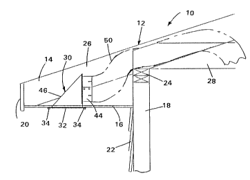
Fig. 1 is a sectional view of a portion of a dwelling, showing the novel eave vent
installed;
Fig. 2 is an enlarged side elevational view of the eave vent;
Fig. 3 is a top view of the novel eave vent;
Fig. 4 is a side elevational view from the left side of the structure in Fig. 2;Fig. 5 is a perspective view of the novel structure; and
Fig. 6 is a side elevational view of a prior art through-wall vent structure.
DESCRIPTION OF THE PREFERRED EMBODIMENT
Referring now specifically to the drawings, the structure depicted in Fig. 1
colllplises a dwelling 12, such as a house or an apartment, having an ove.l~ngi~-g
roofline 14 with a horizontal eave 16 therebeneath extending from the upright structural
wall 18 and the outer facia board 20 of the eave and roofline. Wall 18 is shown to have
a suitable exterior siding 22 and is typically formed of a plurality of spaced upright studs
having a plate 24, e.g., of nominal 2" x 4" material, across the top of the studs. The
roof typically will include a plurality of spaced rafters 26, e.g., of nominal 2" x 8"
material. A plurality of joists 28 will typically extend from the underside of the roof and
on top of plate 24 to the opposite side of the building and/or to an interior supporting
30 wall, in conventional fashion.
Mounted to the underside eave 16 is the novel eave vent 30 which fits into an
opening in the eave. More specifically, the eave vent includes a housing having a lower
horizontal peripheral mounting rim 32 which has fasteners 34 extending through a

2168493

plurality of fastener receiving openings 36 (Fig. 3) shown here to be at the corners. This
eave vent is preferably formed of sheet metal. This peripheral rim defines a gas flow
outlet 38 (Fig. 3) of generally rectangular configuration and shown here to be square to
have more volume to push air through. Extending vertically upwardly from rim 32 is a
5 vertical wall 40 comprising a sheet metal panel having a circular opening 42 therein (Fig.
5). Extending around opening 42 is a cylindrical hose connector 44 slotted as at 44a to
allow slight radial adjustability of this connector for oy~ lum connection to a typical
flexible hose 50. Hose 50 can extend from the inlet connector of eave vent 30 upbetween the rafters and joists in the fashion depicted in Fig. 1 and eventually to the
10 source of the gases, e.g., a clothes dryer or furnace. A diagonal wall 46 extends from
the top portion of vertical wall 40, diagonally away from vertical wall 40, to join
horizontal rim 32. Integrally connPcte~l to all three of these walls, namely the horizontal
rim 32, vertical wall 40, and diagonal wall 46, are a pair of triangular end panels 48 to
close the housing. A closure flapper 54 of square configuration and normally of sheet
15 metal is pivotally mounted along its upper horizontal edge by an integral pivot sleeve 56
adjacent the juncture of diagonal wall 46 with vertical wall 40 such that pivotal movement
from the vertical closed position (Fig. 2) to the diagonal open position will cause the flap
to lie flush against the inside surface of diagonal wall 46 when gas is being forcefully
discharged through the vent. The sleeves 56 (Figs. 2 and 4) extend through slots 54a in
20 flapper 54 and curl upwardly to provide the pivotal connection. It has been found that the
square configuration of this flapper fitted within the parallel vertical side walls or end
walls 48 assures minim~l air flow behind the flapper when air is being discharged, to
prevent back pressure on the flapper tending to close it and thus ullw~nt~d ylcs~urc drop.
The edges of the flapper are preferably closely adjacent the triangular end walls 48. The
25 diagonal wall 46 is at an angle of about 45, preferably at least 45 to vertical wall 40, to
take m~ximllm advantage of the Bernoulli effect of gas flow along the underside of the
eave.
When gas such as hot air or exhaust gas is forced through duct 50 and connector
44 into inlet 42 of the housing, it forces flapper 54 to an open position flush against
30 diagonal wall 46, causing the air or other gas to change direction from the horizontal to a
diagonal flow along the flapper and diagonal wall 46 to outlet 38, where it tends to flow
horizontally along the underside of eave 16 due to the Bernoulli effect, jettisoning
generally horizontally, or at least diagonally ou~waldly, away from the dwelling, for rapid

216~4$3
-


dissipation thel~rlulll. This alleviates back flow and back pressure problem reslllting
from the usual dowllw~rd flow and Bernoulli effect along the outside vertical wall
surface, to cause the gas to strike the ground and reverse. It also elimin~tes debris
collection along the side wall of the structure, characteristic of prior units.
Various minor changes could conceivably be made in the appal~lus within the
illv~lllive concept, which is intended to be limited only by the scope of the appended
claims and the reasonably equivalent structures to those defined therein.

Dessin représentatif
Une figure unique qui représente un dessin illustrant l'invention.
États administratifs

Pour une meilleure compréhension de l'état de la demande ou brevet qui figure sur cette page, la rubrique Mise en garde , et les descriptions de Brevet , États administratifs , Taxes périodiques et Historique des paiements devraient être consultées.

États administratifs

Titre Date
Date de délivrance prévu 2001-06-12
(22) Dépôt 1996-01-31
(41) Mise à la disponibilité du public 1996-08-22
Requête d'examen 1997-12-10
(45) Délivré 2001-06-12
Expiré 2016-02-01

Historique d'abandonnement

Il n'y a pas d'historique d'abandonnement

Historique des paiements

Type de taxes Anniversaire Échéance Montant payé Date payée
Le dépôt d'une demande de brevet 0,00 $ 1996-01-31
Enregistrement de documents 0,00 $ 1996-04-25
Requête d'examen 400,00 $ 1997-12-10
Taxe de maintien en état - Demande - nouvelle loi 2 1998-02-02 100,00 $ 1997-12-30
Taxe de maintien en état - Demande - nouvelle loi 3 1999-02-01 100,00 $ 1998-12-17
Taxe de maintien en état - Demande - nouvelle loi 4 2000-01-31 100,00 $ 1999-12-08
Taxe de maintien en état - Demande - nouvelle loi 5 2001-01-31 150,00 $ 2000-12-21
Taxe finale 300,00 $ 2001-03-12
Taxe de maintien en état - brevet - nouvelle loi 6 2002-01-31 150,00 $ 2001-12-19
Taxe de maintien en état - brevet - nouvelle loi 7 2003-01-31 150,00 $ 2002-12-17
Taxe de maintien en état - brevet - nouvelle loi 8 2004-02-02 150,00 $ 2003-12-16
Taxe de maintien en état - brevet - nouvelle loi 9 2005-01-31 200,00 $ 2004-12-16
Taxe de maintien en état - brevet - nouvelle loi 10 2006-01-31 250,00 $ 2005-12-14
Taxe de maintien en état - brevet - nouvelle loi 11 2007-01-31 250,00 $ 2006-12-15
Taxe de maintien en état - brevet - nouvelle loi 12 2008-01-31 250,00 $ 2007-12-13
Taxe de maintien en état - brevet - nouvelle loi 13 2009-02-02 250,00 $ 2008-12-15
Taxe de maintien en état - brevet - nouvelle loi 14 2010-02-01 250,00 $ 2009-12-15
Taxe de maintien en état - brevet - nouvelle loi 15 2011-01-31 450,00 $ 2010-12-17
Taxe de maintien en état - brevet - nouvelle loi 16 2012-01-31 450,00 $ 2011-12-16
Taxe de maintien en état - brevet - nouvelle loi 17 2013-01-31 450,00 $ 2012-12-20
Taxe de maintien en état - brevet - nouvelle loi 18 2014-01-31 450,00 $ 2013-12-19
Taxe de maintien en état - brevet - nouvelle loi 19 2015-02-02 450,00 $ 2014-12-22
Titulaires au dossier

Les titulaires actuels et antérieures au dossier sont affichés en ordre alphabétique.

Titulaires actuels au dossier
BUILDER'S BEST, INC.
Titulaires antérieures au dossier
ANDERSON, CHARLES B.
KENRICK, CHARLES R.
Les propriétaires antérieurs qui ne figurent pas dans la liste des « Propriétaires au dossier » apparaîtront dans d'autres documents au dossier.
Documents

Pour visionner les fichiers sélectionnés, entrer le code reCAPTCHA :


Pour visualiser une image, cliquer sur un lien dans la colonne description du document. Pour télécharger l'image (les images), cliquer l'une ou plusieurs cases à cocher dans la première colonne et ensuite cliquer sur le bouton "Télécharger sélection en format PDF (archive Zip)" ou le bouton "Télécharger sélection (en un fichier PDF fusionné)".

Liste des documents de brevet publiés et non publiés sur la BDBC .

Si vous avez des difficultés à accéder au contenu, veuillez communiquer avec le Centre de services à la clientèle au 1-866-997-1936, ou envoyer un courriel au Centre de service à la clientèle de l'OPIC.


Description du
Document 
Date
(yyyy-mm-dd) 
Nombre de pages   Taille de l'image (Ko) 
Dessins représentatifs 2001-05-17 1 7
Page couverture 2001-05-17 1 36
Abrégé 1996-05-28 1 23
Page couverture 1996-05-28 1 16
Description 1996-05-28 4 195
Revendications 1996-05-28 1 33
Dessins 1996-05-28 3 49
Dessins représentatifs 1999-08-10 1 9
Correspondance 2001-03-12 1 31
Cession 1996-01-31 8 284
Poursuite-Amendment 1998-01-06 1 28
Poursuite-Amendment 1997-12-10 1 35