Sélection de la langue

Search

Sommaire du brevet 2169017 

Énoncé de désistement de responsabilité concernant l'information provenant de tiers

Une partie des informations de ce site Web a été fournie par des sources externes. Le gouvernement du Canada n'assume aucune responsabilité concernant la précision, l'actualité ou la fiabilité des informations fournies par les sources externes. Les utilisateurs qui désirent employer cette information devraient consulter directement la source des informations. Le contenu fourni par les sources externes n'est pas assujetti aux exigences sur les langues officielles, la protection des renseignements personnels et l'accessibilité.

Disponibilité de l'Abrégé et des Revendications

L'apparition de différences dans le texte et l'image des Revendications et de l'Abrégé dépend du moment auquel le document est publié. Les textes des Revendications et de l'Abrégé sont affichés :

  • lorsque la demande peut être examinée par le public;
  • lorsque le brevet est émis (délivrance).
(12) Brevet: (11) CA 2169017
(54) Titre français: EXCAVATEUR A BENNE, A DEGAGEMENT IMPORTANT ENTRE LES STRUCTURES HAUTE ET BASSE
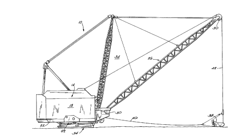
(54) Titre anglais: DRAGLINE WITH HIGH HEADROOM BETWEEN UPPER AND LOWER STRUCTURES
Statut: Périmé
Données bibliographiques
(51) Classification internationale des brevets (CIB):
  • E02F 3/48 (2006.01)
  • E02F 9/12 (2006.01)
(72) Inventeurs :
  • KALLENBERGER, HARVEY J. (Etats-Unis d'Amérique)
(73) Titulaires :
  • HARNISCHFEGER TECHNOLOGIES, INC. (Etats-Unis d'Amérique)
(71) Demandeurs :
  • HARNISCHFEGER CORPORATION (Etats-Unis d'Amérique)
(74) Agent: RIDOUT & MAYBEE LLP
(74) Co-agent:
(45) Délivré: 1999-11-16
(22) Date de dépôt: 1996-02-07
(41) Mise à la disponibilité du public: 1997-03-30
Requête d'examen: 1996-02-07
Licence disponible: S.O.
(25) Langue des documents déposés: Anglais

Traité de coopération en matière de brevets (PCT): Non

(30) Données de priorité de la demande:
Numéro de la demande Pays / territoire Date
08/536,701 Etats-Unis d'Amérique 1995-09-29

Abrégés

Abrégé français

De la machinerie lourde comprenant une structure de support inférieure ayant une surface supérieure et une structure supérieure ayant une surface inférieure généralement horizontale faisant face à la face supérieure de la structure inférieure, la structure supérieure étant soutenue au-dessus de la structure inférieure pour une rotation sur un axe généralement vertical par rapport à la structure inférieure, et la surface inférieure de la structure supérieure comportant une cavité qui se prolonge vers le haut autour de l'axe pour fournir de l'espace pour une personne travaillant sur la machine, la cavité étant définie au moins en partie par une paroi supérieure en dessus et généralement parallèle à la face inférieure, et par plusieurs facettes généralement planes entourant l'axe, chacune des facettes s'étendant transversalement à la paroi supérieure et à la face inférieure.


Abrégé anglais

Heavy machinery comprising a lower support structure having an upper surface, and an upper structure having a generally horizontal lower surface facing the upper surface of the lower structure, the upper structure being supported above the lower structure for rotation relative to the lower structure about a generally vertical axis, and the lower surface of the upper structure having therein an upwardly extending recess surrounding the axis to provide space for a person working on the machinery, the recess being defined at least in part by an upper wall above and generally parallel to the lower surface, and by a plurality of generally planar facets surrounding the axis, each of the facets extending transversely to the upper wall and to the lower surface.

Revendications

Note : Les revendications sont présentées dans la langue officielle dans laquelle elles ont été soumises.


THE EMBODIMENTS OF THE INVENTION IN WHICH AN EXCLUSIVE
PROPERTY OR PRIVILEGE IS CLAIMED ARE DEFINED AS FOLLOWS:

1. A dragline comprising
a lower support structure having a generally horizontal
upper surface, and
an upper structure having a generally horizontal lower
surface facing said upper surface of said lower structure, said
upper structure being supported above said lower structure for
rotation relative to said lower structure about a generally
vertical axis, and said lower surface of said upper structure
having therein an upwardly extending recess surrounding said axis
to provide space for a person working on the machinery, said
recess being defined at least in part by an upper wall above and
generally parallel to said lower surface, and by a plurality of
generally planar facets surrounding said axis, each of said
facets extending transversely to said upper wall and to said
lower surface.
2. A dragline as set forth in claim 1 wherein said recess is
also defined by an outwardly facing inner wall extending between
said upper wall and said lower surface, and by an inwardly facing
outer wall extending between said upper wall and said lower
surface, and wherein said facets form one of said inner and outer
walls.
-8-


3. A dragline as set forth in claim 2 wherein the other of
said inner and outer walls is also formed by a plurality of
generally planar facets surrounding said axis and each extending
transversely to said upper wall and to said lower surface.
4. A dragline as set forth in claim 1 wherein each of said
facets has opposite side edges each having a generally linear
junction with an abutting one of said facets.
5. A dragline as set forth in claim 4 wherein each of said
facets has an upper edge having a generally linear junction with
said upper wall, and has a lower edge having a generally linear
junction with said lower surface.
6. A dragline as set forth in claim 5 wherein said junctions
are supported by respective support plates each having a lower
edge abutting the associated facets at the associated junction,
said support plates extending generally perpendicular to said
lower surface.
7. A dragline as set forth in claim 6 wherein said upper
structure also includes a generally horizontal upper plate spaced
above said lower surface, and wherein each of said support plates
has an upper edge abutting said upper plate.
-9-


8. A dragline as set forth in claim 7 wherein each of said
support plates has opposite generally vertical edges each having
a generally linear junction with an abutting one of said support
plates.

9. A dragline as set forth in claim 1 wherein each of said
facets is a plate.

10. A dragline as set forth in claim 1 wherein each of said
facets is inclined upwardly from said lower surface to said upper
wall.
-10-


11. A dragline comprising
a lower support structure having a generally horizontal
upper surface, and
an upper structure having a generally horizontal lower
surface facing said upper surface of said lower structure, said
upper structure being supported above said lower structure for
rotation relative to said lower structure about a generally
vertical axis, and said lower surface of said upper structure
having therein an upwardly extending recess surrounding said axis
to provide space for a person working on the machinery, said
recess being defined by an upper wall above and generally
parallel to said lower surface, by an outwardly facing inner wall
extending between said upper wall and said lower surface, and by
an inwardly facing outer wall extending between said upper wall
and said lower surface, each of said inner and outer walls being
formed by a plurality of generally planar facets surrounding said
axis, each of said facets being formed by a plate inclined
upwardly from said lower surface to said upper wall.
12. A dragline as set forth in claim 11 wherein each of said
facets has opposite side edges each having a generally linear
junction with an abutting one of said facets.
-11-


13. A dragline as set forth in claim 12 wherein each of said
facets has an upper edge having a generally linear junction with
said upper wall, and has a lower edge having a generally linear
junction with said lower surface.
14. A dragline as set forth in claim 13 wherein said
junctions are supported by respective support plates each having
a lower edge abutting the associated facets at the associated
junction, said support plates extending generally perpendicular
to said lower surface.
15. A dragline as set forth in claim 14 wherein said upper
structure also includes a generally horizontal upper plate spaced
above said lower surface, and wherein each of said support plates
has an upper edge abutting said upper plate.
16. A dragline as set forth in claim 15 wherein each of said
support plates has opposite generally vertical edges each having
a generally linear junction with an abutting one of said support
plates.
-12-


17. A dragline comprising
a lower support structure having a generally horizontal
upper surface, and
an upper structure having a generally horizontal lower
surface facing said upper surface of said lower structure, said
upper structure being supported above said lower structure for
rotation relative to said lower structure about a generally
vertical axis, and said lower surface of said upper structure
having therein an upwardly extending recess surrounding said axis
to provide space for a person working on the machinery, said
recess being defined at least in part by an upper wall above and
generally parallel to said lower surface, and by a plurality of
generally planar facets surrounding said axis, each of said
facets extending transversely to said upper wall and to said
lower surface,
a boom extending from said upper structure, said boom having
thereon a sheave,
a bucket,
a hoist rope extending over said sheave to said bucket for
causing vertical movement of said bucket, and
a drag rope connected to said bucket for causing horizontal
movement of said bucket.
-13-


18. A dragline as set forth in claim 17 wherein said recess
is also defined by an outwardly facing inner wall extending
between said upper wall and said lower surface, and by an
inwardly facing outer wall extending between said upper wall and
said lower surface, and wherein said facets form one of said
inner and outer walls.
19. A dragline as set forth in claim 18 wherein the other
of said inner and outer walls is also formed by a plurality of
generally planar facets surrounding said axis and each extending
transversely to said upper wall and to said lower surface.
20. A dragline as set forth in claim 17 wherein each of
said facets has opposite side edges each having a generally
linear junction with an abutting one of said facets.
21. A dragline as set forth in claim 20 wherein each of
said facets has an upper edge having a generally linear junction
with said upper wall, and has a lower edge having a generally
linear junction with said lower surface.
-14-


22. A dragline as set forth in claim 21 wherein said
junctions are supported by respective support plates each having
a lower edge abutting the associated facets at the associated
junction, said support plates extending generally perpendicular
to said lower surface.
23. A dragline as set forth in claim 22 wherein said upper
structure also includes a generally horizontal upper plate spaced
above said lower surface, and wherein each of said support plates
has an upper edge abutting said upper plate.
24. A dragline as set forth in claim 23 wherein each of
said support plates has opposite generally vertical edges each
having a generally linear junction with an abutting one of said
support plates.
25. A dragline as set forth in claim 17 wherein each of
said facets is a plate.
26. A dragline as set forth in claim 17 wherein each of
said facets is inclined upwardly from said lower surface to said
upper wall.
-15-

Description

Note : Les descriptions sont présentées dans la langue officielle dans laquelle elles ont été soumises.


2169017 HARN9116

DRAGLINE WITH HIGH HEADROOM
BETWEEN UPPER AND LOWER STRUCTURES


BACKGROUND OF THE INVENTION
Field of the Invention
The invention relates to large machines having relatively
rotatable upper and lower structures. More particularly, the
invention relates to draglines.


Discussion of Prior Art
A walking dragline typically includes an upper structure and
a boom which extends upwardly and outwardly from the upper
structure and which has thereon a sheave for supporting a hoist
rope. The hoist rope extends over the sheave to a bucket for
causing vertical movement of the bucket. A drag rope is
connected to the bucket for causing horizontal movement of the
bucket. The upper structure is supported by a tub that sits on
the ground when the dragline is engaged in digging operations.
The upper structure is rotatable relative to the tub about a
vertical pivot axis. A pair of walking mechanisms are mounted on
the opposite sides of the upper structure and are operable ~or
moving the dragline over the ground between digging operations.
Historically, heavy equipment such as draglines with
rotating upper structures have had minimal clearance between the
upper rotating structure and the top of the lower support
structure when employing a flat top for the lower structure.


2 1 690 1 7
HARN91 16
This has made maintenance of equipment in that area, such as the
mechanical and electrical equipment involved with rotating the
upper structure relative to the lower structure, a difficult
task. Improving human access in this area would allow the user
of the equipment to more easily inspect, maintain, and repair the
rotating machinery and any other equipment that may be located in
the area. Some machines have structural elements added to the
bottom surface of the upper deck. These elements often result in
cracking problems with the main structure due to the method of
attachment.

SUMMARY OF THE INVENTION
The invention provides, on the bottom surface of the upper
structure, a contour that greatly enhances accessibility between
the upper and lower structures, without sacrificing the
structural integrity of the upper structure and its ability to
carry the dead weight of the equipment and designed operating
loads, and without increasing the depth of the upper structure or
its total weight. Any change in depth would unnecessarily add to
the size of the structure, presenting manufacturing and shipping
difficulties and increasing cost.
More particularly, the bottom surface of the upper structure
has a circular relief cavity or recess centered on the pivot
axis. The upper wall of the cavity is preferably parallel to the
bottom surface of the upper structure. The inner and outer walls


2 1 690 1 7 HARN9116
of the cavity are formed by multiple planar facets. The number
of facets on the inner and outer walls do not have to be the
same. The structural integrity of the upper structure is
maintained by having all facets inclined relative to the bottom
surface of the upper structure. Each juncture line formed by the
intersection of a facet plane with any adjacent plane (the bottom
surface of the upper structure, the upper wall of the cavity or
an adjacent facet plane) is structurally supported by an internal
support diaphragm or plate normal to the bottom surface of the
upper structure. These diaphragms become integral structural
members of the overall upper structure.
The height provided by the relief cavity provides additional
clearance necessary for improved access between the upper and
lower structures.
Other features and advantages of the invention will become
apparent to those skilled in the art upon review of the following
detailed description, claims and drawings.


216qO17
~9116
DESCRIPTION OF THE DRAWINGS
Figure 1 is a side elevational view of a dragline embodying
the invention.
Figure 2 is a partial vertical cross-sectional view of the
dragline.
Fig. 3 is a partial perspective view of the top of the deck
with the upper plate removed.
Fig. 4 is a partial perspective view of the bottom of the
deck showing the circular recess therein.
Fig. 5 is a top plan view of the portion of the deck shown
in Fig. 3.
Fig. 6 is Fig. 3 enlarged.
Before one embodiment of the invention is explained in
detail, it is to be understood that the invention is not limited
in its application to the details of the construction and the
arrangements of components set forth in the following description
or illustrated in the drawings. The invention is capable of
other embodiments and of being practiced or being carried out in
various ways. Also, it is to be understood that the phraseology
and terminology used herein is for the purpose of description and
should not be regarded as limiting.


2169017 HARN9116
DESCRIPTION OF THE PREFERRED EMBODIMENT
A dragline 10 embodying the invention i8 illustrated in the
drawings. The dragline 10 comprises (Fig. 1) an upper structure
14 including a main housing 18 mounted on top of a deck 22. The
dragline 10 also includes, inside the main housing 18, a bucket
hoist mechanism (not shown) and a bucket drag mechanism (not
shown). A boom 26 extends upwardly and outwardly from the upper
structure 14. The upper end of the boom 26 has thereon a sheave
30. The boom 26 is supported relative to the upper structure 14
by conventional supporting structure 34. The dragline 10 also
includes a bucket 38, a hoist rope 42 extending between the
bucket hoist mechanism and the bucket 38 and over the sheave 30
for causing vertical movement of the bucket 38, and a drag rope
46 extending between the bucket drag mechanism and the bucket 38
for causing horizontal movement of the bucket 38. An operator's
cab 50 is mounted on the upper structure 14.
The dragline 10 further includes a lower structure or tub 54
which sits on the ground and supports the upper structure 14
during digging operations. The tub 54 has an upper surface 56.
The tub 54 is described below in greater detail. The upper
structure 14 is rotatable relative to the tub 54 about a vertical
axis 58 (see Fig. 2) . More particularly, the deck 22 rotates
about a center pintle 62 which is mounted on the lower structure
54 and which is centered on the pivot axis 58. A lifting pin 66
extends along the axis 58 and connects the upper structure 14 to


2 1 6 9 0 1 7 HARN9116
the lower structure 54. ~ bearing assembly 70 supports the upper
structure 14 above the lower structure 54. The bearing assembly
70 includes a circular lower rail 74 on the lower structure 54, a
circular upper rail 78 on the upper structure 14, and a plurality
of rollers 82 between the rail~ 74 and 78. The upper structure
14 is rotated relative to the lower structure 54 by a gear drive
86 which is mounted on the upper structure 14 and which engages a
circular ring gear 90 mounted on the lower structure 54. The
dragline 10 also comprises (see Fig. 1) a pair of walking
mechanisms 92 (only one is shown) which move the dragline 10 over
the ground between digging operations.
The deck 22 has (see Figs. 2 and 4) a lower plate 98
defining a generally horizontal lower surface 102 facing the
upper surface 56 of the tub 54. The deck 22 also includes (see
Fig. 2) a generally horizontal upper plate 106 which is spaced
above the lower surface 102. To provide access for a person
working on the machinery, the lower sur~ace 102 of the deck 22
has therein (see Figs. 2 and 4) an upwardly extending recess 110
surrounding the pivot axis. The recess 110 is defined by a
generally horizontal upper wall 114 above the lower surface 102,
by an outwardly facing inner wall 118 extending between the upper
wall 114 and the lower surface 102, and by an inwardly facing
outer wall 122 extending between the upper wall 114 and the lower
surface 10 2.


21 5 9 0 1 7 ~9116

Each of the walls 118 and 122 is defined by (see Fig. 4) a
plurality of planar facets or plates 126 surrounding the axis.
Each facet 126 is inclined upwardly from the lower surface 102 to
the upper wall 114 and has opposite side edges 130 and opposite
upper and lower edges 134 and 138. Each side edge 130 has a
linear junction with the side edge 130 of an abutting facet 126.
Each upper edge 134 has a linear junction with the upper wall
114, and each lower edge 138 has a linear junction with the lower
surface or plate 98. Each junction is supported by (see Figs. 2,
3 and 5) a respective support plate 142 which extends vertically
and has a lower edge 146 (see Fig. 2) abutting the facets 126
forming the junction. Each support plate 142 also has an upper
edge 150 abutting the upper plate 106, and opposite vertical
edges (not numbered) each having a linear junction with an
abutting support plate 142. All of the plates 98, 106, 126 and
142 are preferably welded to all abutting plates. This
construction maximizes the structural integrity of the deck 22.
As shown in Figs. 5 and 6, additional support plates (not
numbered) are preferably also provided where desirable to
increase the structural integrity of the deck 22.
Various features of the invention are set forth in the
following claims.


Dessin représentatif
Une figure unique qui représente un dessin illustrant l'invention.
États administratifs

Pour une meilleure compréhension de l'état de la demande ou brevet qui figure sur cette page, la rubrique Mise en garde , et les descriptions de Brevet , États administratifs , Taxes périodiques et Historique des paiements devraient être consultées.

États administratifs

Titre Date
Date de délivrance prévu 1999-11-16
(22) Dépôt 1996-02-07
Requête d'examen 1996-02-07
(41) Mise à la disponibilité du public 1997-03-30
(45) Délivré 1999-11-16
Expiré 2016-02-08

Historique d'abandonnement

Il n'y a pas d'historique d'abandonnement

Historique des paiements

Type de taxes Anniversaire Échéance Montant payé Date payée
Le dépôt d'une demande de brevet 0,00 $ 1996-02-07
Enregistrement de documents 0,00 $ 1996-05-02
Taxe de maintien en état - Demande - nouvelle loi 2 1998-02-09 100,00 $ 1997-12-04
Taxe de maintien en état - Demande - nouvelle loi 3 1999-02-08 100,00 $ 1999-01-25
Enregistrement de documents 50,00 $ 1999-08-16
Taxe finale 300,00 $ 1999-08-16
Taxe de maintien en état - brevet - nouvelle loi 4 2000-02-07 100,00 $ 2000-01-14
Taxe de maintien en état - brevet - nouvelle loi 5 2001-02-07 150,00 $ 2001-01-29
Taxe de maintien en état - brevet - nouvelle loi 6 2002-02-07 150,00 $ 2002-01-18
Enregistrement de documents 50,00 $ 2002-06-17
Taxe de maintien en état - brevet - nouvelle loi 7 2003-02-07 150,00 $ 2003-01-21
Taxe de maintien en état - brevet - nouvelle loi 8 2004-02-09 200,00 $ 2004-02-03
Taxe de maintien en état - brevet - nouvelle loi 9 2005-02-07 200,00 $ 2005-01-18
Taxe de maintien en état - brevet - nouvelle loi 10 2006-02-07 250,00 $ 2006-02-01
Taxe de maintien en état - brevet - nouvelle loi 11 2007-02-07 250,00 $ 2007-01-23
Taxe de maintien en état - brevet - nouvelle loi 12 2008-02-07 250,00 $ 2008-01-23
Taxe de maintien en état - brevet - nouvelle loi 13 2009-02-09 250,00 $ 2009-01-26
Taxe de maintien en état - brevet - nouvelle loi 14 2010-02-08 250,00 $ 2010-01-22
Taxe de maintien en état - brevet - nouvelle loi 15 2011-02-07 450,00 $ 2011-01-31
Taxe de maintien en état - brevet - nouvelle loi 16 2012-02-07 450,00 $ 2012-01-17
Taxe de maintien en état - brevet - nouvelle loi 17 2013-02-07 450,00 $ 2013-01-17
Taxe de maintien en état - brevet - nouvelle loi 18 2014-02-07 450,00 $ 2014-01-17
Taxe de maintien en état - brevet - nouvelle loi 19 2015-02-09 450,00 $ 2015-02-02
Titulaires au dossier

Les titulaires actuels et antérieures au dossier sont affichés en ordre alphabétique.

Titulaires actuels au dossier
HARNISCHFEGER TECHNOLOGIES, INC.
Titulaires antérieures au dossier
HARNISCHFEGER CORPORATION
KALLENBERGER, HARVEY J.
Les propriétaires antérieurs qui ne figurent pas dans la liste des « Propriétaires au dossier » apparaîtront dans d'autres documents au dossier.
Documents

Pour visionner les fichiers sélectionnés, entrer le code reCAPTCHA :


Pour visualiser une image, cliquer sur un lien dans la colonne description du document. Pour télécharger l'image (les images), cliquer l'une ou plusieurs cases à cocher dans la première colonne et ensuite cliquer sur le bouton "Télécharger sélection en format PDF (archive Zip)" ou le bouton "Télécharger sélection (en un fichier PDF fusionné)".

Liste des documents de brevet publiés et non publiés sur la BDBC .

Si vous avez des difficultés à accéder au contenu, veuillez communiquer avec le Centre de services à la clientèle au 1-866-997-1936, ou envoyer un courriel au Centre de service à la clientèle de l'OPIC.


Description du
Document 
Date
(yyyy-mm-dd) 
Nombre de pages   Taille de l'image (Ko) 
Dessins représentatifs 1999-12-21 1 15
Page couverture 1999-11-08 1 45
Page couverture 1999-12-21 1 44
Page couverture 1996-05-27 1 16
Abrégé 1996-05-27 1 23
Description 1996-05-27 7 243
Revendications 1996-05-27 8 223
Dessins 1996-05-27 5 218
Revendications 1999-02-24 8 208
Dessins représentatifs 1999-11-08 1 16
Dessins représentatifs 1997-10-23 1 35
Page couverture 1999-12-20 2 76
Cession 1999-08-16 41 1 598
Correspondance 1999-08-16 1 40
Cession 2002-06-17 10 859
Taxes 1999-01-25 1 33
Taxes 1997-12-04 1 32
Correspondance 1999-12-03 2 86
Poursuite-Amendment 1999-12-20 2 46
Correspondance 1996-05-02 1 26
Correspondance 1996-02-07 1 28
Cession 1996-02-07 5 196
Correspondance 1996-02-29 3 115
Poursuite-Amendment 1998-07-14 1 42
Poursuite-Amendment 1999-01-13 1 40
Poursuite-Amendment 1996-05-15 1 34