Note : Les descriptions sont présentées dans la langue officielle dans laquelle elles ont été soumises.
2171054
This invention relates to a display element which
may be used alone as an indicator but will be more commonly
used as a pixel in an array of such elements to form a
changeable display sign. The invention will be found parti-
cularly useful for signs and displays which must be viewed
over wide angles such as bus destination signs. (As distinct
from signs for narrow angle viewing suchas road signs).
The display element is of the type using a rotor
disk defining a median plane, having opposed sides which
respectively contrast and conform with their background
and which is rotatable about a rotation axis approximately
parallel to said median plane to display the bright or
dark sides of the disk in a viewing direction which is
considered the axis of a viewing cone (not necessarily a
surface of revolution) which surrounds the viewing direction.
The stator which forms the background to each disk is
coloured darkly to contrast with the disk bright side; and
conform to the disk dark side. The bright and dark sides
are displayed in the ON and OFF respective positions.
A light emitting diode (LED) corresponding to each
disk is positioned to form part of the disk's pixel when
the bright side is displayed (called the ON position) the LED
being positioned and directed to illuminate the bright
side of the disk when oriented to ON position. The LED is
permanently on so must be masked to the viewer in the OFF
position of the disk.
'Forward' and 'rearward' are respectiveIy, the
1327-129
2171054
directions from the display element toward the viewer, and
the opposite direction.
An 'array' is the entire bus sign or other sign,
composed of 'sub arrays' which are each made up of a
column of individual display elements, or of individual
elements.
Reference to an ~LED' herein is intended to include
a cluster of such LED's.
The 'viewing direction' is the general centre of
the locations (projected on a plane perpendicular to the
viewing direction) from which the display element, or any
array thereof, is intended to be viewed.
The 'viewing cone' surrounds the viewing direction
and includes the projections on such plane of the positions
from which the display element, or an array thereof is
intended to be viewed.
In a preferred aspect of the invention herein
the angle through which the illuminated disks (in plan
view) may be viewed is about 150~ approximately symmetrically
disposed about the longitudinal axis of a bus on which the
array is disposed. However, the direct light from the LEDs
may be viewed over an arc of about 75~ from the longitll~;n~l
axis on the side of the bus toward which the light from the
LED is directed. This is useful since a bus sign is often
viewed from the sidewalk. Thus, for buses for use in mDst c3untries
other than England and Australia, the 75~ sector will be on
the right of the bus center line, and in England and Australia on the left.
1327-129
217105~
It is known to use such a disk augmented by the
end of an optic fibre. See for example patents :
U.S. 4,974,353 dated 04DEC90, Norfolk
U.S. 5,022,171 dated llJUN91, Norfolk, et al
U.S. 5,055,832 dated 08JUN91, Browne
However, optic fibres while suitable for relatively narrow
angle viewing are not so suitable for viewing over wide
angles, as are LED's. Moreover, LED's are cheaper to a
sufficiently marked degree, that a display application with
LED's may be practical where a similar application with
fibres would be impractical.
Other patents have used LED's with a rotating disk.
See for example, U.S. Patent 5,050,325 dated 24SEP91. However
this patent does not provide for masking of the LED by the
disk per se~nor for wide angle viewing. Hence the LED had
to be switched off in OFF state. The design of the present
display element assumes that the LED will be continuously on
while the disk switches between ON and OFF positions, thus
avoiding the cost of individual switching circuitry for each
LED. Such switching requires design complexity and expense.
Accordingly, it is an object of this invention to
provide a display element, for use alone or in an array of
such elements, wherein the appearance of a rotatable flip
disk is augmented in ON orientation by an LED, which LED must
be masked by the disk, to the viewer, in OFF orientation and
wherein the rays from the LED are directed to illuminate only
the bright side of the disk with which it is associated~ and
to be viewed directly.
1327-129
217105~
It is an object of this invention to provide a
display element or an axray thereof allowing, in ON
position, viewing over a wide angular range and in OFF
position masking the rays over a wide angular range, and
preferably. where the rays reflectant from an disk
illuminated by the LED are visible through a sector in
plan view which is symetric with regard to the forward
direction in plan view.
By 'disk viewing direction' herein I mean the
direction approximately perpendicular to the average
attitude of the illuminated disk in ON and OFF position
and perpendicular to its rotary axis. This will not be
parallel to the disk in ON and OFF position since the ON
and OFF disk orientations are slightly offset from each
other to reduce rotation below 180~ where a magnetic
drive is used)for reasons associated with the drive. Where
an array of display elements is used, the viewing direction
is taken as perpendicular to the plane approximating the
locus of the array.
By 'plan view' I mean the view in the direction
perpendicular to the viewing direction and parallel to
the median plane of an array. Plan view in relation to a
bus will therefore be approximately a vertical view but in
other applications it may have any real orientation.
It will be realized from what has already been
said that for a bus destination sign~the plan view will be
in, approximately, a horizontal plane and that the viewing
locations for viewing directly LED light will be all on one side of the
light viewing direction for the illuminated disks.
--4--
1327-129
217105~
It lS an object of this invention to provide a
display element wherein the light source used is markedly
maintenance free and inexpensive in contrast to alternate
designs.
It is an object of this invention to provide a
display element for forming a pixel which is suitable
for relatively large multiple pixel arrays (for example,
of 20 by 40 pixels) to provide good definition in the
sense of providing a small pixel relative to the size
of the array and a pixel having a relatively large
effective area.
By 'effective area' I mean the percentage of the
sign area which is occupied by the bright areas of the
disks when all are ON. This is a measure of the sign's
efficiency even though it may not be strictly accurate
in view of the effects of the light effects of the LED's
and the preferred angle of the disk bright panels to
the viewing direction. The need to have as large an
effective surface as possible renders preferable the use
of rectilinear elements since these tend to have the best
'packing factor' and hence provide the largest ON area in
a display. The nèed to supply pixels, small in area
relative to the size of the array, suggests, therefore the
use of square pixels.
'LED' herein refers to the chip which is mounted
in a lens, although the chip plus lens is elsewhere fre-
quently calledlcollectivelylan LED.
The invention therefore provides, in one aspect,
a display element, or a column or array thereof where the
stator is preferably an open front housing, usually of
1327-129
21710S~
approximately square shape, and a disk designed to rotate
about an axis to display a bright or dark side in the
viewing direction. (The background to the disk, when viewed
in the viewing direction is typically coloured to contrast
with the brignt disk side and to match the dark disk side).
An LED associated with the stator is located and provided
with shroud means so that the LED rays illuminate the bright
side of the disk for viewers on each side of the viewing
directions. Means prevents the escape of LED rays in
directions transverse to the viewing direction.
The preferred drive for the disk is electromagnetic
in accord with techniques well known to those skilled in
the art. However, other drives may be used within the
scope of the invention.
In a preferred form of the invention, a printed
circuit board ('PCB') is mounted on one side of the disk
and an LED mounted so that its rays will illuminate the
bright side of the disk when the latter is in the ON position.
This will depend on the attitude of the disk when ON.
Preferably in ON position, the bright side of the disk is
tilted slightly toward the LED and the LED rays are directed
traverse to the viewing direction. Means, preferably a
housing on the sides of the T.~n lens~(relative to the desired direction
of LED rays); and the PCB on the back, prevent the escape of
rays diverging very much from the desired LED ray direction.
Sufficient divergence of LED rays from the desired LED ray
disk-illuminating direction,exists that viewers on a side-
1327-129
2171054
walk in front of the bus (on one selected side) may view
the direct rays from the LEDs) when the disk is in ON position.
The wall need not be a PCB, within the scope of
the inventiDn. However, it is considered most suitable
since it is then convenient to provide metal strips on the
PCB board, to provide the LED leads.
Preferably, only one side wall is provided rather
than two for each element or column thereof. The opposed
wall is then provided by the adjacent element or columns
thereof in the direction of LED radlation.
In drawings which illustrate a preferred embodi-
ment of the invention :
Figure 1 is a partial view of a column of display
elements in accord with the invention ,
Figure 2A shows an LED, lens and housing assembly
in accord with the invention,
Figure 2B shows a detail of the LED housing and
the PCB,
Figure 3A is a section along the line 3A-3A of
Figure 1 showing section of a disk in ON position displaying
its bright side,
Figure 3B is a second along the lines 3B-3B of
Figure 1 showing a section of a disk in OFF position,
displaying its dark side,
Figure 4 is a front view of a column of display
elements,
Figure S is a schematic view of the front of a
bus with its destination sign formed by an array in accord
--7--
1327-129
2171051
with the invention,
Figure 6 is a schematic section of part of the
bus and sign taken on a vertical plane along the longitudinal
axis of the bus,
F~gure 7 is a view showing the viewing angles
for the illuminated dot and for the LED directly.
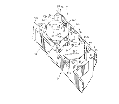
In the drawings Figure 1 shows a portion of a
column of display elements in accord with the invention.
The stator 10 of each element shows an open front housing
with base 12 side walls 14S end walls 14E extending for-
wardly from the base to define a square display element
having a good packing factor and making efficient use of
the display area.
At diame~rically opposed corners of the element
square, towers 16 have wells 18 to receive the spindles
20 of a display disk having a dark side 22D and a bright
side 22B. The disk is notched at 31 to allow it to rotate
past the then adjacent core 26 in moving between limiting
positions.
The drive is, preferably magnetic and a magnet 24
has its N-S axis transverse to the rotation axis of the
disk and is driven by the switching of the cores 26B and 26D which
are always of opposite polarity but switched to cause the
disk to rotate. A permanent magnet 29 with its polar axis
in the viewing direction, V is provided, centered in base 12,
to modify the field provided by cores 26 to provide a
1327-129
CA 021710~4 1998-01-20
hetter starting torque. The drive is preferably in accord
with the teachings of Patent 3,518,664 to MK Taylor, of
June 30/ 1970. The cores' polarities are switched by
surrounding coils 28 from a current source, not shown.
(A magnetically driven disk typically rotates
160~ to <180~ between ON and OFF limiting positions since
a full 180~ rotation is difficult because of lack of
starting (magnetic) torque).
The magnet 24 is preferably contained in the
central layer of a layered disk in accord with the teaching
of U.S. Patents 3,953,274 and 3,871,945, both to Winrow
et al. However, the magnet may be otherwise installed or
mounted.
A different magnetic drive may be used, or a non-
magnetic drive, all within the scope of the invention.
On one side of each element, a side wall 30 is
provided extending forwardly of walls 22E and walls 22S.
As indicated in Figure 4 all the walls 30 of a column of
individual elements 10 can be combined in a single wall
and the elements 10 combined in a single molding. The
wall 30 is preferably a PCB. On the wall facing the disk
is mounted an LED chip (not shown) and lens 32 in a
housing-34. The LED is mounted on the board 30 by its
anode and cathode 36 and 38 with foil conductors 40. The
housing 34 is apertured to allow the rays from the LED
to be emitted in a s~all cone oentered about an LED ray axis A
transverse to the viewing direction and directed at the
217105'1
disk. The disk (in ON position) is tilted slightly toward
the LED (by adjustment of the length of core 26B), whose
end acts as the stop in the ON limiting position Figure 3A
so that the bright surface 22B of the disk is illuminated
by the cone of LED rays about the LED ray axis. The
escape of rays in undesired directions is prevented in
transverse direction by the opaque walls of housing 34
(which has an open rear for the LED connections) and rear-
wardly by wall 30.
The LED ray axis direction is interdependant with
the disks attitude in ON orientation so that it iswithin the
scope of the invention to change the angle of the disk and
its bright side 22B but in such case the housing 34 should
be redirected so that the rays on axis A will illuminate the
bright side 22B.
It should also be noted that some rays from the
LED may pass in front of the disk bright side, (in ON
position only) to reach viewers directly. (See arc DIR in
Figure 7 (about 75~)).
On the other hand the disk bright faces illuminated
by the LED may be seen about the symmetrical arc I. DISk of
about 150~.
The LED lens may be designed, in a manner well
known to those skilled in the art to provide a range of
viewing angles DIR of about 75~ to the right, of the
longitudinal axis of the bus tFigure 9) and to provide a
range of viewing angles I.DISK of about i50O approximately
symmetrical about the longitudinal axis.
--10--
1327-129
217105~
It will be noted that the disk masks, in its
OFF position to a suffi~ier.t degree,the escape of light in the
viewing-dir~ction or in the viewing cone. The end of core 26D
stops the disk in OFF position. The PCB wall 30 prevents the
sideways escape of rays from the LED in both disk attitudes.
Although a wall could be supplied on the other
side of the element it is preferred to have only one wall
30 so that the escape of light is avoided by the wall 30A
(Figures 1 and 6), shown in dotted form, being the wall 30
of the next adjacent element on the side of the element
opposite wall 30.
Figure 4 shows a seven element column with five
of the elements showing the bright side 22B and two of
the elements showing the dark side 22D. Figure 6 also
shows the wall 30A of the next element in the array.
Figu~e S shows a bus carrying an array showing a
destination. The schematic Figure 7 is not indicative
of pixel to array size. In fact the destination sign
could be, for example, 20 pixels high and, for example 40
pixels wide.
Figure 6 is demonstrative of how close the array
A may be to the windshield C in the bus B. This can be
achieved because of the lighting provided intrinsically of
the element by the LEDs. This is in contrast to the larger
array windshield spacing of a prior art array which had to
be set back from the windshield to allow for the presence of
1327-129
.. .. . . .. . .. . . . ...
CA 021710~4 1998-01-20
bus mounted lighting to shine rearward on the array.
Because the inventive array may be placed close
to the windshield it must frequently be curved in plan
view to fit the curving contour of the windshield. Hence
the array is preferably composed of columns which are only
one element wide, as in Figure 6, and of single elements
to the extent necessary to complement the modules.
Figure 9 indicates preferred range of viewing
angles DISK of about 150~ for the illuminated disks
and an asymmetric range of viewing angles DIR of about 75~
for direct viewing of the LEDs.
The assymetry shown will be applied where the
adjacent sidewalk is to the right of the bus, that is most
countries other than U.K. or Australia. Buses for U.K. or
Australia may be produced with the elements ' mirror image'
reversed from left to right. In some cases the elements
as shown may simply be inverted.
There is no limitation on the shape of the disk
but square or rectangular provides a more efficient use
of the space.
Although the rotation axes of the disk are shown
as diagonal, vertical or horizontal axes may be used within
the scope of the invention. Thus, the invention may for
example,be used with disks having vertical axes and elongated
shapes are shown in U.S. Patent 4,577,427 to John Browne
dated March 25, 1986
-12-
2171054
Although the ends of cores 26B and 26D act as the
stops for the disk in ON and OFF position, respectively,
determining the disks attitude in these positions, the
stops may be otherwise provided and the cores used only
for magnetic drive.
1327-129