Note : Les descriptions sont présentées dans la langue officielle dans laquelle elles ont été soumises.
X171380
A POLYMER ELECTROLYTE FUEL CELL AND A POLYMER ELECTROLYTE FUEL
CELL SYSTEM WHICH SUPPLY ANODE-SIDE CHANNELS WITH A GAS-LIQUID
MIXTURE
BACKGROUND OF THE INVENTION
(1) Field of the invention
The present invention is related to a polymer electrolyte
fuel cell and a polymer electrolyte fuel cell system.
(2) Description of the Related Art
A,polymer electrolyte fuel cell is made up of a unit cell
composed of an anode layer, a cathode layer, and a solid-
polymer film disposed therebetween, a member which has channels
facing the anode layer, and~a member which has channels facing
the cathode layer.
The polymer electrolyte fuel cell is supplied with fuel
gas, for example, hydrogen-rich fuel gas through the anode-
side channels, and with oxidizer gas, such as air, through the
cathode-side channels, thereby generating electricity through
an electro-chemical reaction.
Most polymer electrolyte fuel cells in a current use are
composed of a plurality of separators and a plurality of unit
cells which are stacked alternately in order to obtain a higher
voltage. Here, each of the separators has fuel gas channels
and oxidizer gas channels.
A problem faced by such polymer electrolyte fuel cells
is that the heat generated during operation must be partially
1
2111380
removed. Since heat radiation is not enough to maintain a
predetermined temperature of between about 50°C and 100°C, most
polymer electrolyte fuel cells have to be provided with cooling
channels per several unit cells.
As another problem, while a polymer electrolyte fuel cell
is in operation, its solid-polymer film must be kept moist to
maintain its ion conductivity. The water to be generated from
the reaction between the fuel gas and the oxidizer gas
contributes to the moistening of the solid-polymer film to some
extent, although since it is not sufficient, additional water
must be supplied from outside the cell main body.
In view of these problems, most polymer electrolyte fuel
cells are provided with a~.humidifier outside the cell main
body to humidify the fuel gas and the oxidant gas, and further
provided with cooling channels within the cell main body.
In contrast, Japanese Patent Publication No. 1-140562
(U. S. Serial No. 076,970) discloses~a polymer electrolyte fuel
cell which moistens the solid-polymer film by supplying the
fuel gas with water spray using an aspirator, and cools the
cell main body by having the supplied water evaporate from the
cathode layers.
However, the cooling performance of the water evaporation
from the cathode layers is not sufficient for polymer
electrolyte fuel cells which are large-sized or have a high
output density.
2
2171380
SUMMARY OF THE INVENTION
In view of these problems, the object of the present
invention is to provide a polymer electrolyte fuel cell and a
polymer electrolyte fuel cell system which moisten the solid-
polymer film without providing a humidifier which humidifies
the fuel gas or the oxidizer gas, and which cools down the cell
main body without providing cooling channels.
The object of the present invention is achieved by a
polymer electrolyte fuel cell which comprises the following
components:
a cell main body which includes a unit cell composed of
an anode layer, a cathode layer, and a solid-polymer film
disposed between the anodelayer and the cathode layer, and a
member which is provided with a plurality of channels facing
the anode layer;
a mixture supply unit which supplies the plurality of
channels with a gas-liquid mixture which essentially consists
of fuel gas and water; and
an oxidant gas supply unit which supplies the cathode
layer with oxidant gas.
The object of the present invention is also achieved by
a polymer electrolyte fuel cell system which comprises the
following units:
a cell main body which includes a unit cell composed of
an anode layer, a cathode layer, and a solid-polymer film
disposed between the anode layer and the cathode layer, and a
3
2171380
member which is provided with a plurality of channels facing
the anode layer;
a mixture generator which generates a gas-liquid mixture
by mixing water with fuel gas which is supplied from a fuel gas
supply source;
a mixture supply unit which supplies the plurality of
channels with the gas-liquid mixture which has been generated
by the mixture generator; and
an oxidant gas supply unit which supplies the cathode
layer with oxidant gas.
The polymer electrolyte fuel cell and the polymer
electrolyte fuel cell system which have the above-explained
construction have no need of providing a humidifier and
internal cooling channels. This is because the channels are
supplied with the gas-liquid mixture, so that the dispersion
performance of the fuel gas onto the anode layers can be
improved, and the water can function to cool down the cell main
body.
By dispersing the fuel gas in the gas-liquid mixture into
the water, the dispersion performance of the fuel gas onto the
anode layers can be further improved, and the water can
function to cool down the cell main body efficiently.
By forming the cell main body into the alternate stack of
the plurality of unit cells and the plurality of plates, the
cell main body can be cooled down without a cooling plate.
By bubbling the fuel gas into the water which has been
4
- 2171380
supplied to a manifold, the gas-liquid mixture can be generated
within the manifold, and since the gas-liquid mixture is
directly distributed among the channels, each channel can be
supplied with a well-balanced gas-liquid mixture.
By recovering a gas-liquid mixture which has been used in
the cell main body for reproduction, the utilization of fuel
gas can be improved because the fuel gas supplier has only to
supply the exact amount of gas which has been consumed by the
cell reaction.
By separating a recovered gas-liquid mixture into fuel gas
and water, the water can be used to generate a new gas-liquid
mixture.
By using hydrogen as the fuel gas, the system can perform
a stable operation for a long time period because the
composition of the fuel gas never changes.
By recycling water which has been obtained in the gas-
liquid separator, only the exact amount of water which has been
lost mainly in evaporation through the solid-polymer film can
be supplied.
By generating a gas-liquid mixture by bubbling fuel gas
into the water which is reserved in a water tank, the
dispersion performance of the fuel gas and the cooling effects
can be both improved because the gas-liquid mixture includes
fuel gas which is finely dispersed into the water.
By positioning the exit of each channel as high as or
higher than the opening, and by providing the water tank lower
5
CA 02171380 2003-04-17
than the opening of each channel, the gas-liquid mixture
which has been generated by the mixture generator can be
supplied to each channel due to the pressure and buoyancy
of the gas phase. Consequently, there is no need of
providing a pump which supplies the gas-liquid mixture.
In addition, by recovering the gas-liquid mixture from the
exit of each channel and separating it into fuel gas and
water, the fuel gas can be reused. consequently, the fuel
gas which has been used in the cell main body is
circulated to generate electricity, so that the
utilization of fuel gas can be improved because the fuel
gas supplier has only to supply the exact amount of gas
which has been consumed.
By connecting the gas-liquid separation tank and the
water tank, water can be circulated for recycle.
In another aspect, the present invention provides a
solid-polymer fuel cell system, comprising:
a cell main body comprising:
a plurality of unit cells, each of the plurality
of unit cells comprising an anode layer, a cathode
layer and a solid-polymer film disposed between the
anode layer and the cathode layer; and
a plurality of plates, each provided with a
plurality of channels facing a respective anode
layer, the plurality of unit cells and the plurality
of plates being accumulated alternately, the cell
main body being provided with a manifold in
6
CA 02171380 2003-04-17
communication with each channel of the plurality of
plates;
a gas-liquid mixture generator, which is located
in the manifold and is supplied with liquid water and
fuel gas separately, for internally generating a gas-
liquid mixture and for supplying the plurality of
channels with the generated gas-liquid mixture; and
an oxidizing gas supply in communication with
the cathode layers for supplying the cathode layers
with oxidizing gas.
BRIEF DESCRIPTION OF THE DRAWINGS
These and other objects, advantages and features of
the invention will become apparent form the following
description thereof taken in conjunction with the
accompanying drawings which illustrate a specific
embodiment of the invention. In the drawings:
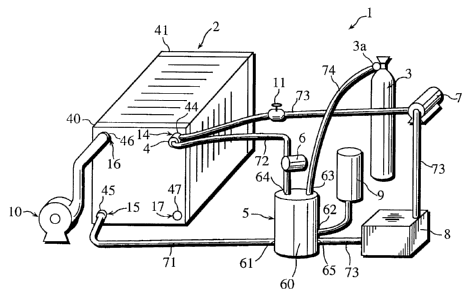
FIG. 1 is a perspective view of the entire
construction of the polymer electrolyte fuel cell system
of the first embodiment.
FIG. 2 is a schematic diagram of the polymer
electrolyte fuel cell system shown in FIG. 1.
6a
2171380
FIG. 3 is an exploded perspective view of the construction
of the cell main body 2 and the gas-liquid mixture unit 4.
FIG. 4 is a sectional view of the upper manifold 14 and
the gas-liquid mixture unit 4.
FIG. 5 is a perspective view of the entire construction
of the polymer electrolyte fuel cell system of the second
embodiment.
FIG. 6 is a schematic diagram of the system shown in FIG.
5.
DESCRIPTION OF THE PREFERRED EMBODIMENTS
<EMBODIMENT 1>
(The entire construction of the polymer electrolyte fuel cell
system 1 of the present embodiment)
FIG. 1 is a perspective view of the entire construction
of the polymer electrolyte fuel cell system 1 of the present
embodiment, and FIG. 2 is a schematic diagram thereof.
As shown in these drawings, the polymer electrolyte fuel
cell system 1 is composed of a cell main body 2 which generates
electricity with air and a gas-liquid mixture, a fuel gas tank
3 as a fuel gas supplier, a gas-liquid mixture unit 4 attached
to the cell main body 2 to generate a gas-liquid mixture from
fuel gas and water, a gas-liquid separator 5 which recovers the
gas-liquid mixture from the cell main body 2 and separates it
into a fuel gas layer and a water layer, a fuel gas pump 6
7
2171380
which supplies the gas-liquid mixture unit 4 with fuel gas, a
circulating water pump 7 which circulates water within the
system 1, a heat exchanger 8 which cools down the circulating
water, a water supply tank 9 to supply water, and an air supply
fan 10 which supplies the cell main body 2 with air.
In the present embodiment, a hydrogen cylinder is used as
the fuel gas tank 3.
FIG. 3 is an exploded perspective view of the construction
of the cell main body 2 and the gas-liquid mixture unit 4.
The cell main body 2 is composed of a plurality of unit
cells 20 and a plurality of separators 30 stacked alternately,
and a pair of end boards 40 and 41 shown in FIG. 4, which
sandwich the alternately,stacked unit cells 20 and the
separators 30 therebetween. In the present embodiment, there
are six unit cells 20 and seven separators 30.
Each of the unit cells 20 consists of an anode layer 22
shown in FIG. 2, a cathode layer 23, and a solid polymer film
21 disposed therebetween.
Each separator 30 has an anode-side channel set 31 on the
side which faces the anode layer 22, and a cathode-side channel
set 32 on the other side which faces the cathode layer 23 shown
in FIG. 2.
In FIG. 3, the anode layers 22 and the cathode-side
channel sets 32 are not shown because they are behind the
cathode layers 23 and the anode-side channel set 31,
respectively.
8
21 l 1380
An unillustrated water repellant current collector is
provided between each anode layer 22 and each anode-side
channel set 31, and also between each cathode layer 23 and
each cathode-side channel set 32.
The solid-polymer films 21 are 0.13mm thick rectangular
films which are made from Nafion 115 (Du Pont, U.S.A.), and
each solid-polymer film 21 has four holes 24-27 at the corners
to form internal manifolds.
The anode layers 22 and the cathode layers 23, both of
which are made from carbon-supported platinum and have a
predetermined thickness, are pressed onto the center of the
solid-polymer films 21 with a hot press. The amount of
platinum is regulated to be'0.7mg/cm2.
The separators 30, which are approximately the same size
as the solid polymer films 21, each has four holes 34-37 at the
corners to form the internal manifolds in the same manner as
the solid polymer films 21.
The anode-side channel sets 31 are formed in a vertical
direction, whereas the cathode-side channel sets 32 are formed
in a horizontal direction.
The holes 34 and the holes 35 are diagonally opposite to
each other on the separators 30. To connect each hole 34,
each hole 35, and each anode-side channel set 31, a manifold
groove 38 and a manifold groove 39 are respectively provided
above and below the anode-side channel set 31, which runs in
the vertical direction.
9
2171380
In the same manner, the holes 36 and the holes 37 are
diagonally opposite to each other on the separators 30. To
connect each hole 36, each hole 37, and each cathode-side
channel set 32, a manifold groove and a manifold groove are
provided along either side of the cathode-side channel set 32,
which runs in the horizontal direction.
The end board 40 also has four holes 44-47 shown in FIG.
1 so that four cylindrical manifolds 14-17 whose openings are
on the end board 40 side are formed in the direction in which
the unit cells 20 and the separators 30 are stacked. The upper
manifolds 14 and 16 consist of the holes 24, 34, and 44, and
the holes 26, 36, and 46, respectively. The lower manifolds
and 17 consist of the holes 35 and 45, and the holes 27, 37,
and 47, respectively.
15 In the present embodiment, these manifolds 14, 15, 16,
and 17 are used to supply a gas-liquid mixture, to expel the
gas-liquid mixture, to supply air, and to expel the air,
respectively.
The gas-liquid mixture unit 4, which is positioned inside
the upper manifold 14 is composed of a cylindrical bubbler 51
which bubbles fuel gas into water in the upper manifold 14, a
cylindrical holder 52 which holds the bubbler 51 inside the
upper manifold 14, and a cylindrical stopper 53 to seal the
opening of the upper manifold 14.
FIG. 4 is a sectional view of the upper manifold 14 and
the gas-liquid mixture unit 4. As shown in FIGS. 3 and 4, the
217138
bubbler 51 has approximately the same length as the upper
manifold 14 and is made from a sintered metal with a 5E~m mesh
diameter. The fuel gas which has entered the gas-liquid
mixture unit 4 via its gas opening 54, which pierce the
cylindrical stopper 53 is evenly dispersed into the water in
the cylindrical holder 52.
The cylindrical holder 52, which fits into the upper
manifold 14, has a slit 52a along the side which faces the
manifold groove 38.
The cylindrical stopper 53 is provided with a water
opening 55 through which water enters the cylindrical holder
52. The cylindrical stopper 53 seals the opening of the upper
manifold 14 when it is fitted into the hole 44 of the end board
40.
The following will be explained with reference to FIGS.
1 and 2 again.
The gas-liquid separator 5 is composed of a sealed
container 60, a recovered gas-liquid mixture opening 61 on the
side, a fuel gas opening 63 and a fuel gas exit 64 on the top,
and a water opening 62 and a water exit 65 at the bottom.
The recovered gas-liquid mixture opening 61 is connected
with the lower manifold 15 via a pipe 71. The fuel gas exit
64 is connected with the gas opening 54 of the gas-liquid
mixture unit 4 via a pipe 72, which runs through the fuel gas
pump 6. The water opening 65 is connected with the water
opening 55 of the cylindrical stopper 53 via a pipe 73, which
11
21 l 1380
runs through the circulating water pump 7 and the heat
exchanger 8.
The fuel gas opening 63 is connected with the fuel gas
tank 3 via a pipe 74 with a pressure regulating valve 3a, which
regulates the supply of fuel gas to the sealed container 60
under a predetermined pressure.
(The operation of the polymer electrolyte fuel cell system 1)
In the gas-liquid mixture unit 4, the fuel gas which has
been supplied through the gas opening 54 is dispersed into the
water which has been supplied through the water opening 55 into
the cylindrical holder 52, and as a result, a gas-liquid
mixture is generated.
The generated gas-liquid mixture goes through each
manifold groove 38, is distributed among the channels of each
anode-side channel set 31 while generating electricity, united
at each manifold groove 39, and expelled from the lower
manifold 15.
While the gas-liquid mixture goes through the anode-side
channel sets 31, it moistens the solid polymer films 21, and,
at the same time, cools down the celh main body 2 functioning
as cooling water.
Since the generated gas-liquid mixture is directly
distributed among the channels of each anode-side channel set
31 without going through a pipe, each anode-side channel set
31 is supplied with a well-balanced gas-liquid mixture. The
12
2171380
amount of the gas-liquid mixture to be supplied to each anode-
side channel set 31, and the ratio between water and fuel gas
in the gas-liquid mixture is regulated by changing the amount
of water to be supplied with the circulating water pump 7 and
the amount of gas to be supplied with the fuel gas pump 6.
This regulation enables the function of the gas-liquid mixture
as a cooling medium and the security of sufficient fuel gas to
the anode layers 22.
As mentioned before, the water repellant current collector
provided between each anode layer 22 and each anode-side
channel set 31 prevents each anode layer 22 from being sunken
into the gas-liquid mixture during a long operation. As a
result, fuel gas is successfully supplied to the reaction site
of each anode layer 22.
The gas-liquid mixture which has been expelled from the
lower manifold 15 travels through the pipe 71 to the gas-
liquid separator 5 via the recovered mixture opening 61. In
the gas-liquid separator 5, the gas-liquid mixture is separated
into a fuel gas layer (top layer) and a water layer (bottom
layer ) . The fuel gas which has been supplied from the fuel gas
tank 3 is mixed with the fuel gas which has entered the gas-
liquid separator 5 through the fuel gas opening 63, recovered
as a fuel gas layer, and expelled from the fuel gas exit 64.
The fuel gas thus expelled is sent to the gas-liquid mixture
unit 4 through the gas opening 54 with the fuel gas pump 6.
On the other hand, the water separated from the fuel gas
13
2171380
by the gas-liquid separator 5 is cooled down to a predetermined
temperature while it travels through the heat exchanger 8, and
enters the gas-liquid mixture unit 4 through the water opening
55 with the circulating water pump 7.
In the gas-liquid mixture unit 4, the fuel gas sent with
the fuel gas pump 6 is bubbled into the water sent with the
circulating water pump 7, and as a result, a new gas-liquid
mixture is generated.
As explained hereinbefore, in the system 1, a new gas-
liquid mixture is generated from the gas-liquid mixture
recovered from the cell main body 2 and the fuel gas sent from
the fuel gas tank 3, and supplied to the cell main body 2.
When the water level~in the gas-liquid separator 5 is
lowered, water is supplied from the water supply tank 9 through
the water supply opening 62, so that the amount of the
circulating water is maintained at a certain level even if
some water is lost in evaporation while it travels through the
unit cells 20 to the cathode-side channel sets 32.
The air which has been supplied by the air supply fan 10
to the upper manifold 16 travels through a manifold groove,
is distributed among the channels of each cathode-side channel
set 32, united at the manifold groove, and expelled from the
lower manifold 17 outside the cell main body 2.
(The effects of the polymer electrolyte fuel cell system 1)
In the system 1, the solid-polymer films 21 are moistened
14
2171380
while the gas-liquid mixture travels through the anode-side
channel sets 31. Consequently, there is no need of providing
a humidifier which humidifies the fuel gas or oxidant gas.
In addition, the gas-liquid mixture which travels through
the anode-side channel sets 31 cools down the cell main body
2 by functioning as cooling water. This cooling effect is
greater than that is obtained from the evaporation of water
from the cathode layers 23.
Furthermore, the gas-liquid mixture to be generated by the
gas-liquid mixture unit 4 consists of water and fuel gas finely
dispersed into the water. Consequently, the water cools the
cell main body 2 as efficiently as ordinal cooling water, while
the fuel gas is efficiently'supplied to the anode layers 22.
<EMBODIMENT 2>
(The entire construction of the polymer electrolyte fuel cell
system 101 of the present embodiment)
FIG. 5 is a perspective view of the entire construction
of the polymer electrolyte fuel cell system 101 of the present
embodiment, and FIG. 6 is a schematic diagram thereof. In the
present embodiment, the like components are labeled with like
reference numerals with respect to the first embodiment, and
the description of these components is not repeated.
In common with the system 1 of the first embodiment, the
polymer electrolyte fuel cell system 101 includes the cell main
2171380
body 2, the fuel gas tank 3, the gas-liquid mixture unit 4, the
fuel gas pump 6, the water supply tank 9, and the air supply
fan 10. The system 101 further includes a separation tank 102
which recovers a gas-liquid mixture from the cell main body 2
and separates it into a fuel gas layer and a water layer, a
buffer tank 103 which mixes the fuel gas obtained in the
separation tank 102 with the fuel gas from the fuel gas tank
3, and a cooling fan 104 which cools down the water layer of
the separation tank 102.
In the system 101, the gas-liquid mixture unit 4 is
positioned inside the lower manifold 15 of the cell main body
2, and a gas-liquid mixture is expelled from the upper manifold
14, whereas in the system ~~.of the first embodiment, the gas-
liquid mixture unit 4 is positioned inside the upper manifold
14, and a gas-liquid mixture is expelled from the lower
manifold 15.
The separation tank 102 is disposed beside the end board
40, approximately as high as the cell main body 2. The
separation tank 102 is composed of a sealed container 110 with
a recovered mixture opening 111 on a side surface, a fuel gas
exit 113 on a top surface, a supply water opening 112 and a
water exit 114 on other side surfaces.
The cooling fan 104 sends air to the bottom of the
separation tank 102, thereby cooling the water layer in the
separation tank 102 down to a predetermined temperature.
The recovered mixture opening 111 is connected with the
16
- 217130
upper manifold 14 via a pipe 121. The fuel gas exit 113 is
connected with the buffer tank 103 via a pipe 122. The gas
opening 54 of the gas-liquid mixture unit 4 is connected with
the buffer tank 103 via a pipe 123, which goes through the fuel
gas pump 6.
The separation tank 102 and the lower manifold 15 are
connected with each other as a result that the water exit 114
and the water opening 55 of the gas-liquid mixture unit 4 are
connected with each other via a pipe 124.
The fuel gas tank 3 and the buffer tank 103 are connected
with each other via a pipe 125 with the pressure regulating
valve 3a. The pressure regulating valve 3a regulates the
amount of fuel gas to be supplied into the buffer tank 103
under a fixed pressure.
When the water level of the separator tank 102 is lowered,
water is supplied from the water supply tank 9 with a water
supply pump 9a, so that the amount of circulating water is
maintained at a certain level.
( The operation of the polymer electrolyte fuel cell system 101 )
Since the water contained in the separation tank 102 is
maintained at a certain level, there is always some water at
the bottom of the separation tank 102. Also, the lower
manifold 15, which is connected with the separation tank 102,
is automatically supplied with water.
In the gas-liquid mixture unit 4, the fuel gas to be
17
.- 217130
supplied through the gas opening 54 is dispersed into the water
in the lower manifold 15, and as a result, a gas-liquid mixture
is generated.
The gas-liquid mixture thus generated travels upward due
to the pressure and buoyancy of the gas phase. To be more
specific, the gas-liquid mixture travels through each manifold
groove 39, is distributed among the channels of each anode-
side channel set 31, goes up along the channels, is united at
each manifold groove 38, and expelled from the upper manifold
14.
The gas-liquid mixture expelled from the upper manifold
14 enters the separation tank 102 via the pipe 121, and is
separated into a fuel gas layer (top layer) and a water layer
(bottom layer). The fuel gas layer enters the buffer tank 103
via the pipe 122.
In the buffer tank 103, the fuel gas from the fuel gas
tank 3 and the fuel gas from the pipe 122 are mixed. The mixed
fuel gas is supplied to the gas-liquid mixture unit 4 via the
gas opening 54 with the fuel gas pump 6.
On the other hand, the water layer separated from the fuel
gas layer in the separation tank 102 is cooled down to a
predetermined temperature with the cooling fan 104, and
automatically sent to the lower manifold 15 via the water
opening 55 through the pipe 124.
In the gas-liquid mixture unit 4, the fuel gas from the
buffer tank 103 is dispersed into the water from the separation
18
2171380
tank 102, and as a result, a new gas-liquid mixture is
generated.
As explained hereinbefore, in the system 101, a new gas-
liquid mixture is generated from the gas-liquid mixture which
has been recovered from the cell main body 2 and the fuel gas
to be supplied from the fuel gas tank 3, and supplied to the
cell main body 2.
In the present embodiment, the anode-side channel sets 31
are disposed in the vertical direction; however, the exits may
be disposed as high as or higher than the openings because the
gas-liquid mixture proceeds by the pressure and buoyancy of the
gas phase.
(The effects of the polymer electrolyte fuel cell system 101)
In common with the system 1 of the first embodiment, the
solid-polymer films 21 in the system 101 are moistened while
the gas-liquid mixture travels through the anode-side channel
sets 31, so that there is no need of providing a humidifier
which humidifies fuel gas or oxidizer gas.
In addition, the gas-liquid mixture which travels through
the anode-side channel sets 31 cools down the cell main body
2 by functioning as cooling water.
In the system 101, the gas-liquid mixture automatically
travels through the anode-side channel sets 31 due to the
pressure of the fuel gas to be supplied to the gas-liquid
mixture unit 4 and the buoyancy of the gas-liquid mixture, so
19
2171380
that the circulating water pump 7 of the first embodiment is
dispensable.
(Others)
In the present invention, a gas-liquid mixture travels
through the channels facing the anode layers 22, and the fuel
gas contained in the gas-liquid mixture is supplied to the
anode layers 22. The reason of water being supplied in the
form of a mixture with fuel gas is that hydrogen as an active
principle of the fuel gas has an excellent dispersion
performance to allow water be supplied onto the anode layers
22, so that there is no harm on the cell performance.
In contrast, the oxidant gas to be supplied onto the
cathode layers 23 has poor dispersion performance, so that
supplying it in the form of a mixture with water would decrease
the cell performance.
In the above embodiments, hydrogen is used as fuel gas,
so that the composition of the fuel gas which circulates within
the system never changes during a long time operation, which
leads to the achievement of a stable cell.
In contrast, when a hydrogen-rich reformed gas is used as
fuel gas, the components other than hydrogen are believed to
accumulate in the circulating fuel gas during a long time
operation. To avoid the accumulation, the circulating fuel
gas should preferably be replaced by fresh gas from the fuel
gas tank 3 in the case of a long time operation.
211130
If hydrogen is used as the fuel gas, the system 1 or 101
can perform a stable operation for a long time period because
the composition of the fuel gas never change.
Furthermore, in the cell main body 2 of the above
embodiments, the gas-liquid mixture unit 4 is positioned in an
internal manifold; however, it may be positioned in an external
manifold.
In the above embodiments, a gas-liquid mixture is
generated by bubbling fuel gas into water which travels through
a manifold with the bubbler 51 made from a sintered metal.
However, a spray nozzle or an aspirator may be used instead of
the bubbler 51. Furthermore, a gas-liquid mixture generator
which is composed of a water. tank and a bubbler may be provided
separately from the cell main body 2.
The cell main body 2 of the above embodiments is composed
of six unit cells and seven separators stacked alternately;
however, the cell main body 2 may be composed of a single unit
cell.
Although the present invention has been fully described
by way of examples with reference to the accompanying drawings,
it is to be noted that various changes and modifications will
be apparent to those skilled in the art. Therefore, unless
such changes and modifications depart from the scope of the
present invention, they should be construed as being included
therein.
21