Sélection de la langue

Search

Sommaire du brevet 2173424 

Énoncé de désistement de responsabilité concernant l'information provenant de tiers

Une partie des informations de ce site Web a été fournie par des sources externes. Le gouvernement du Canada n'assume aucune responsabilité concernant la précision, l'actualité ou la fiabilité des informations fournies par les sources externes. Les utilisateurs qui désirent employer cette information devraient consulter directement la source des informations. Le contenu fourni par les sources externes n'est pas assujetti aux exigences sur les langues officielles, la protection des renseignements personnels et l'accessibilité.

Disponibilité de l'Abrégé et des Revendications

L'apparition de différences dans le texte et l'image des Revendications et de l'Abrégé dépend du moment auquel le document est publié. Les textes des Revendications et de l'Abrégé sont affichés :

  • lorsque la demande peut être examinée par le public;
  • lorsque le brevet est émis (délivrance).
(12) Brevet: (11) CA 2173424
(54) Titre français: DISPOSITIF POUR AUGMENTER LA PRESSION DANS UNE PERCEUSE MANUELLE
(54) Titre anglais: APPARATUS FOR INCREASING HAND DRILL PRESSURE
Statut: Réputé périmé
Données bibliographiques
Abrégés

Abrégé français

Appareil pour accroître la pression d'une perceuse à main comprenant un levier muni d'une première et d'une deuxième extrémité. Un manchon, fixé transversalement sur le levier, à une certaine distance de la première extrémité, est conçu pour être glissé sur le manche d'une perceuse à main. Un fil d'ancrage est doté d'une première et d'une deuxième extrémité, la première est fixée sur la première extrémité du levier et la deuxième est équipée d'un crochet destiné à ancrer la corde d'ancrage à une pièce à travailler. Le levier fournit un gain mécanique, ce qui permet d'accroître la pression de la perceuse à main sur la pièce à travailler.


Abrégé anglais


An apparatus for increasing hand drill pressure includes
a lever having a first end and a second end. A sleeve is
affixed transversely to the lever spaced from the first end.
An anchor line is provided having a first end and a second end.
The first end of the anchor line is secured to the first end
of the lever. A hook is provided on the second end of the
anchor line. The sleeve slides over a handle of a hand drill.
The hook is used to anchor the anchor line to a workpiece.
The lever provides a mechanical advantage to increase the
pressure with which the hand drill engages the workpiece.

Revendications

Note : Les revendications sont présentées dans la langue officielle dans laquelle elles ont été soumises.


6

THE EMBODIMENTS OF THE INVENTION IN WHICH AN EXCLUSIVE PROPERTY
OR PRIVILEGE IS CLAIMED ARE DEFINED AS FOLLOWS:

1. An apparatus for increasing hand drill pressure,
comprising:
a lever having a first end and a second end;
a sleeve affixed transversely to the lever spaced from the
first end whereby the lever may be pivotally attached to a
handle of a hand drill;
an anchor line having a first end and a second end, the
first end of the anchor line being secured to the first end of
the lever;
means for anchoring the second end of the anchor line to
a workpiece such that the anchor line provides resistance to
the lever pivoting about the hand drill when an initial force
is exerted upon the second end of the lever, thereby resulting
in a resultant force pressing the hand drill into the workpiece
that exceeds the initial force exerted upon the second end of
the lever.

2. The apparatus as defined in Claim 1, wherein the means for
anchoring the second end of the anchor line to a workpiece
includes a hook on the second end of the anchor line.

3. The apparatus as defined in Claim 1, wherein means are
provided for adjusting the length of the anchor line.

4. The apparatus as defined in Claim 3, wherein the lever is
tubular having a central bore, the anchor line is fabricated
from a chain having a plurality of links, the anchor line
passes through the central bore of the tubular lever, the means
for adjusting the length of the anchor line being chain
engaging means positioned at one of the first end and the
second end of the lever.


7

5. An apparatus for increasing hand drill pressure,
comprising:
a lever having a first end and a second end;
a sleeve affixed transversely to the lever spaced from the
first end, whereby the lever may be pivotally attached to a
handle of a hand drill;
an anchor line having a first end and a second end, the
first end of the anchor line being secured to the first end of
the lever; and
a hook on the second end of the anchor line, whereby the
second end of the anchor line is attached to a workpiece to
provide resistance to the lever pivoting about the handle of
the hand drill when an initial force is exerted upon the second
end of the lever, resulting in a resultant force pressing the
hand drill into the workpiece that exceeds the initial force
exerted upon the second end of the lever.

6. The apparatus as defined in Claim 5, wherein the lever is
tubular having a central bore, the anchor line being fabricated
from a chain having a plurality of links, the anchor line
extending through the central bore of the tubular lever, a
selected one of the plurality of links of the chain being
positioned in a slot at the first end of the lever, thereby
securing the anchor line to the first end of the lever in a
manner that enables the length of the anchor line to be
adjusted.


8

7. In combination:
a hand drill having a chuck for receiving a drill bit and
a handle disposed at right angles to the chuck;
an apparatus for increasing hand drill pressure,
comprising:
a lever having a first end and a second end;
a sleeve affixed transversely to the lever spaced
from the first end, the sleeve sliding over the handle of the
hand drill thereby pivotally attaching the lever to the hand
drill;
an anchor line having a first end and a second end,
the first end of the anchor line being secured to the first end
of the lever;
means for anchoring the second end of the anchor line
to a workpiece such that the anchor line provides resistance
to the lever pivoting about the hand drill when pressure is
exerted upon the second end of the lever, thereby resulting in
a force pressing the hand drill into the workpiece that exceeds
the pressure exerted upon the second end of the lever.

8. The combination as defined in Claim 7, wherein a hook is
positioned on the second end of the anchor line, the means for
anchoring the second end of the anchor line to the workpiece
including wrapping the anchor line around the workpiece with
the hook engaging the anchor line.

9. An apparatus for assisting drilling with a hand drill, the
apparatus comprising:
a lever having a fulcrum end and a handle end;
a transverse receptacle on the lever for receiving a
handle of a hand drill, the receptacle being closer to the
fulcrum end than to the handle end; and
a tether having a first end secured to the fulcrum end and
a free end.

Description

Note : Les descriptions sont présentées dans la langue officielle dans laquelle elles ont été soumises.

~173g2g


TITLE OF THE INVENTION:

Apparatus for increasing Hand Drill Pressure

NA~E OF INVENTOR:

Robert Lloyd Hamilton

FIELD OF THE INVENTION

The present invention relates to an apparatus for
increasing hand drill pressure.
R~R~OUND OF THE INVENTION
The advantage of applying pressure to a drill when
drilling through a workpiece of wood or metal has long been
recognized. Apparatus, commonly known as "drill presses",
have been developed which support a drill with a depending
drill bit above a workpiece and include press mechanisms which
lower the drill, thereby forcing the drill bit into the
workpiece during drilling operations. When manually drilling
using a hand drill, a workman is prone to fatigue and muscle
strain. This fatigue and muscle strain is exacerbated when the
workman is working in a confined space or in an awkward
position.


SUMMARY OF THE INVENTION

What is required is an apparatus for increasing hand drill
pressure in a fashion similar to that of a drill press.

According to the present invention there is provided an
apparatus for increasing hand drill pressure which includes a
lever having a first end and a second end. Means is provided

~17342~


for pivotally attaching the lever to a hand drill spaced from
the first end. An anchor line is provided having a first end
and a second end. The first end of the anchor line is secured
to the first end of the lever. Means is provided for anchoring
the second end of the anchor line to a workpiece. The anchor
line provides resistance to the lever pivoting about the hand
drill when pressure is exerted upon the second end of the
lever, the force pressing the hand drill into the workpiece
exceeding the pressure exerted upon the second end of the
lever.

The apparatus, as described above, provides a mechanical
advantage which increases the force with which the hand drill
is pressed toward the workpiece. A force exerted upon the
second end of the lever translates to a multiple of that force
at the hand drill. The multiple is dependent upon the length
of the lever.

Once the underlying teaching of the invention i8
understood modifications can be made. The preferred means for
anchoring the second end of the anchor line to the workpiece
is a hook positioned on the second end of the anchor line.
It will be appreciated that there are other means which can be
used. The preferred means for pivotally attaching the hand
drill to the lever includes a sleeve affixed transversely to
the lever. It will, similarly, be appreciated that there are
other means which can be used.

BRIEF D~CRTPTION OF THE DRAWINGS

These and other features of the invention will become more
apparent from the following description in which reference is
made to the appended drawings, wherein:
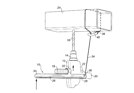
FIGURE 1 is perspective view of an apparatus for
increasing hand drill pressure constructed in accordance with
the teachings of the present invention.

~1739~


FIGURE 2 is a side elevation view of an alternative
embodiment of the invention.
FIGURE 3 is a front elevation view of the alternative
embodiment illustrated in FIGURE 2.


DE~TT~n _ -~rTPTION OF THE ~K~r~KK~v EMBODIMENT

The preferred embodiment, an apparatus for increasing hand
drill pressure generally identified by reference numeral 10,
will now be described with reference to FIGURES 1 through 3.

Referring to FIGURE 1 there is illustrated a hand drill
12 having a chuck 14 for receiving a drill bit 16. Hand drill
12, as illustrated, in one of the larger industrial models that
has two handles 18 and 20. Both handles 18 and 20 are disposed
substantially at right angles to chuck 14. Only handle 20 has
a trigger 22. A workpiece to be drilled is illustrated in the
form of a tubular member 24.

20Apparatus 10 includes a lever 26 having a first end 28 and
a second end 30. A sleeve 32 is affixed transversely to lever
26 spaced a short distance from first end 28. An anchor line
34 is provided having a first end 36 and a second end 38.
First end 36 of anchor line 34 is secured to first end 28 of
25lever 26. A hook 40 is secured to second end 38 of anchor
line 34.

The use and operation of apparatus 10 will now be
described with reference to FIGURE 1. Sleeve 32 slides over
30one of handles 18 or 20 of hand drill 12. In this case,
handle 18 has been used to maximize access to trigger 22 on
handle 20. By sliding sleeve 32 over handle 18, lever 26 is
pivotally attached to hand drill 12. Second end 38 of anchor
line 34 is wrapped around tubular member 24 and hook 40 engaged
with anchor line 34. The drilling operation can now commence
with hand pressure being applied to second end 30 of lever 26.
Anchor line 34 provides resistance to lever 26 pivoting about

~173424


handle 18 of hand drill 12 when pressure is exerted upon second
end 30 of lever 26. With anchor line 34 preventing lever 26
from pivoting, the force applied to second end 30 of lever 26
exerts a force upon handle 18 pressing hand drill 12 toward
tubular member 24. As drill bit 16 goes deeper into tubular
member 24, pivotal movement of sleeve 32 about handle 18 allows
lever 26 to change its position without adversely effecting the
angle of entry of drill bit 16. The mechanical advantage
provided by levers is well known. It will be understood that
the force pressing hand drill 12 toward tubular member 24
exceeds the pressure exerted upon second end 30 of lever 26.

Referring to FIGURES 2 and 3, there is illustrated an
alternative embodiment in which the length of anchor line 34
is adjustable. Referring to FIGURE 2, lever 26 is tubular and,
as a consequence, has a central bore 42. Anchor line 34 is
fabricated from a chain 44 having a plurality of links 46.
Chain 44 extends through central bore 42 of tubular lever 26.
Referring to FIGURE 3, a selected one 48 of plurality of links
46 of chain 44 is positioned in a slot 50 at first end 28 of
lever 26. This secures anchor line 34 to first end 28 of lever
26 in a manner that enables the length of anchor line 34 to be
adjusted.

It will be apparent to one skilled in the art that
apparatus 10 is well suited for use by a workman working in
confined spaces or in an awkward position. It will also be
apparent to one skilled in the art that apparatus 10 shortens
drilling time, reduces the effort re~uired of the workman and
lessens the possibility of muscle injury. It will finally be
apparent to one skilled in the art that modifications may be
made to the illustrated embodiment without departing from the
spirit and scope of the invention as hereinafter defined in the
Claims. There are a variety of materials suitable for use as
anchor line 34; including a chain, wire cable, rope, and the
like. Hand drill 12 could be manufactured with apparatus 10
"built in" to it's design. The length of lever 26 and the

-- 21~3~24

positioning of the fulcrum point are all matters of design
choice.

Dessin représentatif
Une figure unique qui représente un dessin illustrant l'invention.
États administratifs

Pour une meilleure compréhension de l'état de la demande ou brevet qui figure sur cette page, la rubrique Mise en garde , et les descriptions de Brevet , États administratifs , Taxes périodiques et Historique des paiements devraient être consultées.

États administratifs

Titre Date
Date de délivrance prévu 2000-05-16
(22) Dépôt 1996-04-03
(41) Mise à la disponibilité du public 1997-10-04
Requête d'examen 1998-03-27
(45) Délivré 2000-05-16
Réputé périmé 2013-04-03

Historique d'abandonnement

Il n'y a pas d'historique d'abandonnement

Historique des paiements

Type de taxes Anniversaire Échéance Montant payé Date payée
Le dépôt d'une demande de brevet 0,00 $ 1996-04-03
Requête d'examen 200,00 $ 1998-03-27
Taxe de maintien en état - Demande - nouvelle loi 2 1998-04-03 50,00 $ 1998-03-27
Taxe de maintien en état - Demande - nouvelle loi 3 1999-04-05 50,00 $ 1999-03-16
Taxe finale 150,00 $ 2000-02-16
Taxe de maintien en état - Demande - nouvelle loi 4 2000-04-03 50,00 $ 2000-02-16
Taxe de maintien en état - brevet - nouvelle loi 5 2001-04-03 75,00 $ 2001-03-21
Taxe de maintien en état - brevet - nouvelle loi 6 2002-04-03 75,00 $ 2002-03-22
Taxe de maintien en état - brevet - nouvelle loi 7 2003-04-03 75,00 $ 2003-03-31
Taxe de maintien en état - brevet - nouvelle loi 8 2004-04-05 100,00 $ 2004-03-11
Taxe de maintien en état - brevet - nouvelle loi 9 2005-04-04 100,00 $ 2005-03-10
Taxe de maintien en état - brevet - nouvelle loi 10 2006-04-03 125,00 $ 2006-03-23
Taxe de maintien en état - brevet - nouvelle loi 11 2007-04-03 125,00 $ 2007-03-20
Taxe de maintien en état - brevet - nouvelle loi 12 2008-04-03 125,00 $ 2008-03-20
Taxe de maintien en état - brevet - nouvelle loi 13 2009-04-03 125,00 $ 2009-03-19
Taxe de maintien en état - brevet - nouvelle loi 14 2010-04-05 125,00 $ 2010-03-29
Taxe de maintien en état - brevet - nouvelle loi 15 2011-04-04 225,00 $ 2011-03-31
Titulaires au dossier

Les titulaires actuels et antérieures au dossier sont affichés en ordre alphabétique.

Titulaires actuels au dossier
HAMILTON, ROBERT LLOYD
Titulaires antérieures au dossier
S.O.
Les propriétaires antérieurs qui ne figurent pas dans la liste des « Propriétaires au dossier » apparaîtront dans d'autres documents au dossier.
Documents

Pour visionner les fichiers sélectionnés, entrer le code reCAPTCHA :


Pour visualiser une image, cliquer sur un lien dans la colonne description du document. Pour télécharger l'image (les images), cliquer l'une ou plusieurs cases à cocher dans la première colonne et ensuite cliquer sur le bouton "Télécharger sélection en format PDF (archive Zip)" ou le bouton "Télécharger sélection (en un fichier PDF fusionné)".

Liste des documents de brevet publiés et non publiés sur la BDBC .

Si vous avez des difficultés à accéder au contenu, veuillez communiquer avec le Centre de services à la clientèle au 1-866-997-1936, ou envoyer un courriel au Centre de service à la clientèle de l'OPIC.


Description du
Document 
Date
(yyyy-mm-dd) 
Nombre de pages   Taille de l'image (Ko) 
Dessins représentatifs 2000-03-16 1 6
Dessins 1998-12-14 2 33
Revendications 1998-12-14 3 112
Page couverture 2000-03-16 1 41
Dessins représentatifs 1997-11-06 1 6
Page couverture 1996-07-11 1 14
Abrégé 1996-07-11 1 18
Description 1996-07-11 5 186
Dessins 1996-07-11 3 26
Revendications 1996-07-11 3 99
Page couverture 1997-11-06 1 41
Poursuite-Amendment 1998-12-14 7 205
Poursuite-Amendment 1999-04-30 2 3
Correspondance 2011-04-20 1 11
Taxes 2002-03-22 1 33
Correspondance 2011-04-20 1 15
Taxes 2003-03-31 1 26
Cession 1996-04-03 3 125
Poursuite-Amendment 1998-03-27 1 45
Poursuite-Amendment 1999-06-09 4 159
Correspondance 2000-02-16 1 35
Taxes 1998-03-27 1 38
Taxes 1999-03-16 1 36
Taxes 2004-03-11 1 27
Taxes 2005-03-10 1 25
Taxes 2006-03-23 1 26
Taxes 2007-03-20 1 26
Taxes 2008-03-20 2 68
Correspondance 2008-03-20 2 69
Taxes 2010-03-29 1 201
Taxes 2009-03-19 1 33
Correspondance 2011-03-31 3 155
Correspondance 2012-07-27 5 234