Sélection de la langue

Search

Sommaire du brevet 2175410 

Énoncé de désistement de responsabilité concernant l'information provenant de tiers

Une partie des informations de ce site Web a été fournie par des sources externes. Le gouvernement du Canada n'assume aucune responsabilité concernant la précision, l'actualité ou la fiabilité des informations fournies par les sources externes. Les utilisateurs qui désirent employer cette information devraient consulter directement la source des informations. Le contenu fourni par les sources externes n'est pas assujetti aux exigences sur les langues officielles, la protection des renseignements personnels et l'accessibilité.

Disponibilité de l'Abrégé et des Revendications

L'apparition de différences dans le texte et l'image des Revendications et de l'Abrégé dépend du moment auquel le document est publié. Les textes des Revendications et de l'Abrégé sont affichés :

  • lorsque la demande peut être examinée par le public;
  • lorsque le brevet est émis (délivrance).
(12) Brevet: (11) CA 2175410
(54) Titre français: DISPOSITIF SERVANT A NETTOYER DES PLANCHES A IMPRIMER
(54) Titre anglais: DEVICE FOR CLEANING PRINTING CYLINDERS
Statut: Réputé périmé
Données bibliographiques
(51) Classification internationale des brevets (CIB):
  • B41F 35/02 (2006.01)
  • B41F 35/00 (2006.01)
(72) Inventeurs :
  • GOTTLING, JOSEF (Allemagne)
  • PETERSEN, GODBER (Allemagne)
  • STAMME, RAINER (Allemagne)
(73) Titulaires :
  • MANROLAND AG (Allemagne)
(71) Demandeurs :
  • MAN ROLAND DRUCKMASCHINEN AG (Allemagne)
(74) Agent: NORTON ROSE FULBRIGHT CANADA LLP/S.E.N.C.R.L., S.R.L.
(74) Co-agent:
(45) Délivré: 2001-10-23
(22) Date de dépôt: 1996-04-30
(41) Mise à la disponibilité du public: 1996-11-05
Requête d'examen: 1996-04-30
Licence disponible: S.O.
(25) Langue des documents déposés: Anglais

Traité de coopération en matière de brevets (PCT): Non

(30) Données de priorité de la demande:
Numéro de la demande Pays / territoire Date
295 07 416.7 Allemagne 1995-05-04

Abrégés

Abrégé anglais


A complete cleaning system for printing cylinders
within a rotary printing press, by which a reactive
erasing of ink-bearing layers, including the removal
of filling materials from a gravure printing form, and
a cleaning of ink from all form and transfer cylinders
are possible during the printing process or during
printing pauses. At least one erasing device is
provided which emits a jet of water under pressure
that can be directed against the corresponding outer
surface of each desired cylinder so that, on the one
hand, all traces of ink can be removed and, on the
other hand, a reactive erasing of ink-conducting
layers including filling materials from a gravure
printing-form cylinder is possible.

Revendications

Note : Les revendications sont présentées dans la langue officielle dans laquelle elles ont été soumises.


-7-


The embodiments of the invention in which an exclusive property
or privilege is claimed are defined as follows:


1. A device for cleaning all ink transfer cylinders mounted within a
rotary printing press, the device comprising a plurality of cleaning
apparatuses operative to emit a pressurized jet of water, each one of said
cleaning apparatuses being arranged axially to a respective one of the
cylinders so as to extend over an entire width of the cylinder, and being
configured to direct the jet of water in a substantially radial direction
relative to the respective one of the cylinders, against an outer surface of
the respective one of the cylinders so as to remove all traces of ink,
including filling materials of a gravure printing form cylinder and
reactively erase ink bearing layers so that the cylinder is immediately
reimageable; each cleaning apparatus being arranged over a width of the
respective cylinder to be cleaned so that the cylinder is movable rotatably
below the cleaning apparatus, the cleaning apparatus including a housing
which opens towards the outer surface of the cylinder and defines a
working space, and further comprising pump and suction means for
evacuating the working space.
2. A device according to claim 1, and further comprising, for each
cylinder to be cleaned, a doctor operatively arranged to scrape excess
moisture off the outer surface of the cylinder.
3. A device according to claim 2, wherein the doctor is a rubber
doctor.
4. A device according to claim 1, and further comprising, for each
cylinder to be cleaned, drying means for removing excess moisture from
the outer surface of the cylinder.
5. A device according to claim 4, wherein the drying means
includes an air knife.
6. A device according to claim 4, wherein the drying means
includes a dry roller.


-8-


7. A device according to claim 1, wherein the housing is configured
to be arrangeable in an offset printing unit so that all cylinders can be
cleaned during printing.
8. A device according to claim 1, wherein the cleaning apparatuses
are configured to be arrangeable in a gravure printing press and the
printing cylinders include a gravure printing form cylinder and ink transfer
cylinders, the cleaning apparatuses including a separate cleaning apparatus
for each of the cylinders so that both an erasing of a gravure printing form
cylinder by washing filling material out of recessed locations of a network
of cells in the form cylinder can be effected, as well as cleaning of the
transfer cylinders.
9. A device according to claim 1, and further comprising means for
heating the jet of water to about 85°C.
10. A device according to claim 1, and further comprising means for
supplying water to the working space.
11. A device according to claim 1, and further comprising a plurality
of nozzles arranged in the housing so as to direct the jet of water against
the cylinder surface.
12. A device for cleaning printing cylinders within a rotary printing
press, the device comprising, for each printing cylinder, separate cleaning
means for emitting a pressurized jet of water, in a substantially radial
direction relative to the respective one of the cylinders, against a
corresponding outer surface of the cylinder so as to remove all traces of ink
and reactively erase ink bearing layers so that the cylinder is immediately
reimageable, including filling materials, each cleaning means being
arranged over a width of the respective cylinder to be cleaned so that the
cylinder is movable rotatably below the cleaning means, the cleaning
means including a housing which opens towards the outer surface of the
cylinder and defines a working space, and further comprising pump and
suction means for evacuating the working space.

Description

Note : Les descriptions sont présentées dans la langue officielle dans laquelle elles ont été soumises.


2175410
,. -- 1

DEVICE FOR CLEANING PRlN lNG CYT.TNn~R.

RAck~round of the Invention
The present invention relates to a device for
cleaning printing cylinders within a rotary printing
press.

De8cription of the Prior Art
From German application P 42 16 636, a device is
already known for the repeated reactive erasing of the
ink-bearing layer, i.e. of the organic substance
parts, from the surface of an image-bearing printing
form on a cylinder. This ink-bearing layer is
produced, for instance, by a thermographic, ink-jet,
or electrostatic process. For reuse, the material
forming the printing locations must be removed or
erased so that the surface of the printing form can
again bear an image.
The erasing device taught by this reference has
at least one nozzle, but preferably several nozzles
arranged alongside of each other which can be
connected together by a commercial high-pressure
cleaning system. The erasing device is arranged in
the printing press along the entire printing form
width and over a region of the surface of the printing
form. Since the printing form is passed rotating
below the erasing device, the entire surface of the
printing form can be erased. The nozzles of the
erasing device are provided with a covering which is
open towards the printing form and serves as
protection of the environment. The covering defines a
working space and is connected to a pump for removing
both the water introduced into the working space and
the coating which has been removed.
EP 0 368 177 Bl discloses a gravure cylinder in
which a solid substance which can be liquefied by the

` 2175~10
-- 2

action of energy is introduced into each cell of a raw
form in an amount inversely proportional to the amount
of ink to be transferred. After a printing has been
effected, in order to reestablish the gravure printing
form for a further design after the remaining ink has
been washed off, an erasing device is applied, which
liquefies the filling material in the cells by means
of a source of heat and removes it by means of a
wiping and/or blowing or sucking device.
Summary of the Invention
It is an object of the present invention to
provide a complete cleaning system for printing
cylinders within a rotary printing press by which a
reactive erasing of ink-bearing layers is possible,
including the removal of filling materials from a
gravure printing form and a removal of ink from all
form and transfer cylinders during the printing
process or during pauses in the printing process.
Pursuant to this object, and others which will
become apparent hereafter, one aspect of the present
invention resides in a device or system for cleaning
printing cylinders within a rotary printing press,
which device includes, for each printing cylinder, a
separate cleaning apparatus that is operative to emit
a pressurized jet of water and is arranged to direct
the jet of water against a corresponding outer surface
of a cylinder or a sleeve on the cylinder so as to
remove all traces of ink and reactively erase ink-
bearing layers, including any filling materials, on
the cylinder or a cylinder sleeve surface.
(Hereinafter, it will be understood that reference to
the outer surface of the cylinder encompasses and
applies equally well to the outer surface of a sleeve
if one is mounted on the cylinder.)
Due to the fact that for every ink transfer

217S410


cylinder, i.e. both for the form cylinder or cylinders
and for the transfer or rubber-blanket cylinder or
cylinders, a separate erasing device is provided,
there is developed in the rotary printing press an
entire cleaning system by which a reactive erasing of
ink-bearing layers, including the removal of filling
materials from a gravure printing form and the removal
of ink from all form and transfer cylinders, is
possible even during the printing process.
For this purpose, the erasing device mentioned
previously can be used, and is arranged axially over
the width of the cylinder to be cleaned. Water,
together with the ink and possibly the filling
materials, or organic substance parts, can be drawn
out of the cylinder by the erasing device.
Furthermore, in another embodiment of the
invention, a doctor blade for scraping-off excess
moisture from the surface of the cylinder is arranged
behind the erasing device, seen in the direction of
rotation of the cylinder to be cleaned. The doctor
blade is preferably in the form of a rubber doctor.
For the same purpose, namely in order to remove
excess moisture from the surface of the cylinder, a
drying device can be used. Such a drying device can
be either an air knife or a dry roller.
In principle, any means, including a dry fleece,
which eliminates excess moisture from the surface of
the cylinder after the cleaning process could be used.
The various features of novelty which
characterize the invention are pointed out with
particularity in the claims annexed to and forming a
part of the disclosure. For a better understanding of
the invention, its operating advantages, and specific
objects attained by its use, reference should be had
to the drawing and descriptive matter in which there
are illustrated and described preferred embodiments of

- 2175~10
- 4

the invention.

Brief Description of the Drawings
Fig. 1 schematically shows an offset printing
press with a cleaning system pursuant to the
present invention;
Fig. 2 schematically shows a rotary printing
press for indirect gravure with the
inventive cleaning system;
Figs. 3a-3c show an erasing device which is
connected to a high-pressure cleaning
system; and
Fig. 4 is a schematic representation of the
erasing device of Fig. 3, employed in
connection with a gravure-printing-form
cylinder.

Det~ile~ Description of the Preferred Embodiments
Referring to Fig. 1, a rubber-against-rubber
printing unit 1 of an offset printing press comprises,
in a known manner, printing-form cylinders 4 and
rubber-blanket cylinders 3, as well as two inking
units 5 and two damping units 6.
The printing-form cylinder 4 may be a cylinder
which is provided with an image in the form of an ink-
bearing layer by means of a thermographic process and
which is suitable for offset printing, having an
erasing device 8 which can be applied in a known
manner, or else a plate cylinder which has been
prepared for flat printing.
Similar to the arrangement with respect to the
form cylinder 4, erasing devices 7 are also provided
for the transfer or rubber-blanket cylinders 3. In
the direction of rotation of the cylinders 3, 4 which
are to be cleaned, in each case a rubber doctor blade
9, 10 is placed against the surface of the

217~i410

-- 5

corresponding cylinder downstream of the erasing
device. The cylinder 3, 4 can also be cylinders that
have sleeves mounted thereon, as is known in the art.
Fig. 2 shows the invention arranged in a doctor
gravure printing unit 11 for indirect ink-fed
rotogravure.
By gravure there is to be understood here a
generic term for all printing processes having
printing elements which are located below the surface
of the form.
In a known manner, the gravure printing unit 11
comprises a gravure printing-form cylinder 12 having a
doctor 13 for scraping the ink off all non-printing
locations prior to printing, so that the ink remains
only in the recessed image locations. The printing
unit 11 further includes a rubber-blanket cylinder 14
and an impression cylinder 15 between which a web W
passes. Erasing devices 17, 18, each having a rubber
doctor blade 19, 20 arranged behind the erasing device
17, 18 as seen in the direction of rotation of the
cylinders 12, 14, are associated both with the gravure
printing-form cylinder 12 and with the rubber-blanket
cylinder 14.
In this way, the erasing of the gravure printing
form on the cylinder 12 by washing the ink and the
filling material out of the recesses and the cleaning
of the transfer cylinder 14 are possible during
printing or during a pause in printing.
As filling material, there are preferably used
thermoplastic fillers such as thermoplastic. For
example, polyolefins, vinyl polymers, polyamides,
polyesters, polyacetals, polycarbonates and in part
also polyurethanes and ionomers can be used as the
filling material.
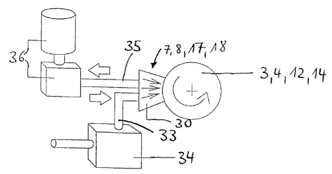
Figs. 3a-c show an erasing device 7, 8 or 17, 18
in detail. Against the cylinder 3, 4, 12, 14 there is

217~410


placed a high-pressure erasing chamber 30. Within the
housing 31 of the erasing chamber 30 are a plurality
of high-pressure nozzles 32 arranged in a row parallel
to the axis of the cylinder. A water feed 33 extends
into the chamber 30 and a water discharge 35 extends
out of it. Fig. 3a is a front view of the erasing
chamber 30, as seen from the cylinder 3, 4. Fig. 3b
is a side view of the erasing chamber 30. The water
feed 33 extends from a commercial high-pressure
cleaning system 34 arranged ahead of the erasing
chamber, while the water outlet 35 leads to a pump and
suction device combination 36 with filter, arranged
behind the erasing chamber 30, as shown in Fig. 3c.
Fig. 4 shows this erasing device 30 to 36 applied
to a photo-engraved roller, and therefore a gravure
printing form cylinder 12. The high pressure cleaning
system 34 contains a compressor 40 and a heating
container 50. The erasing chamber water outlet 35
leads to the pump and suction combination 36 which
includes a separator 41 for air and a pump with filter
system 42 for the water outlet 43. The air can be
drawn off by means of a suction motor 44 of a suction
pot 45.
The jet of water is preferably heated to about
85C and thus has sufficient energy to also dissolve
out the image filling material in the cells of a
filled gravure raw printing form. The water in the
work space of the erasing device can also be drawn off
together with the so-called "gap air".
The invention is not limited by the embodiments
described above which are presented as examples only
but can be modified in various ways within the scope
of protection defined by the appended patent claims.

Dessin représentatif
Une figure unique qui représente un dessin illustrant l'invention.
États administratifs

Pour une meilleure compréhension de l'état de la demande ou brevet qui figure sur cette page, la rubrique Mise en garde , et les descriptions de Brevet , États administratifs , Taxes périodiques et Historique des paiements devraient être consultées.

États administratifs

Titre Date
Date de délivrance prévu 2001-10-23
(22) Dépôt 1996-04-30
Requête d'examen 1996-04-30
(41) Mise à la disponibilité du public 1996-11-05
(45) Délivré 2001-10-23
Réputé périmé 2010-04-30

Historique d'abandonnement

Il n'y a pas d'historique d'abandonnement

Historique des paiements

Type de taxes Anniversaire Échéance Montant payé Date payée
Le dépôt d'une demande de brevet 0,00 $ 1996-04-30
Enregistrement de documents 0,00 $ 1996-08-01
Taxe de maintien en état - Demande - nouvelle loi 2 1998-04-30 100,00 $ 1998-03-23
Taxe de maintien en état - Demande - nouvelle loi 3 1999-04-30 100,00 $ 1999-03-22
Taxe de maintien en état - Demande - nouvelle loi 4 2000-05-01 100,00 $ 2000-03-17
Taxe de maintien en état - Demande - nouvelle loi 5 2001-04-30 150,00 $ 2001-03-27
Taxe finale 300,00 $ 2001-07-18
Taxe de maintien en état - brevet - nouvelle loi 6 2002-04-30 150,00 $ 2002-03-20
Taxe de maintien en état - brevet - nouvelle loi 7 2003-04-30 150,00 $ 2003-03-18
Taxe de maintien en état - brevet - nouvelle loi 8 2004-04-30 200,00 $ 2004-03-19
Taxe de maintien en état - brevet - nouvelle loi 9 2005-05-02 200,00 $ 2005-03-24
Taxe de maintien en état - brevet - nouvelle loi 10 2006-05-01 250,00 $ 2006-03-24
Taxe de maintien en état - brevet - nouvelle loi 11 2007-04-30 250,00 $ 2007-03-26
Taxe de maintien en état - brevet - nouvelle loi 12 2008-04-30 250,00 $ 2008-03-25
Enregistrement de documents 100,00 $ 2008-07-11
Titulaires au dossier

Les titulaires actuels et antérieures au dossier sont affichés en ordre alphabétique.

Titulaires actuels au dossier
MANROLAND AG
Titulaires antérieures au dossier
GOTTLING, JOSEF
MAN ROLAND DRUCKMASCHINEN AG
PETERSEN, GODBER
STAMME, RAINER
Les propriétaires antérieurs qui ne figurent pas dans la liste des « Propriétaires au dossier » apparaîtront dans d'autres documents au dossier.
Documents

Pour visionner les fichiers sélectionnés, entrer le code reCAPTCHA :


Pour visualiser une image, cliquer sur un lien dans la colonne description du document. Pour télécharger l'image (les images), cliquer l'une ou plusieurs cases à cocher dans la première colonne et ensuite cliquer sur le bouton "Télécharger sélection en format PDF (archive Zip)" ou le bouton "Télécharger sélection (en un fichier PDF fusionné)".

Liste des documents de brevet publiés et non publiés sur la BDBC .

Si vous avez des difficultés à accéder au contenu, veuillez communiquer avec le Centre de services à la clientèle au 1-866-997-1936, ou envoyer un courriel au Centre de service à la clientèle de l'OPIC.


Description du
Document 
Date
(yyyy-mm-dd) 
Nombre de pages   Taille de l'image (Ko) 
Page couverture 2001-10-03 1 36
Dessins représentatifs 2001-10-03 1 6
Abrégé 1996-08-08 1 20
Description 1996-08-08 6 258
Revendications 1996-08-08 2 77
Page couverture 1996-08-08 1 20
Dessins 1996-08-08 4 55
Revendications 2000-12-06 2 96
Revendications 2000-10-04 2 97
Dessins représentatifs 1998-04-01 1 6
Poursuite-Amendment 1998-10-09 2 63
Cession 1996-04-30 11 352
Poursuite-Amendment 1999-04-09 8 297
Poursuite-Amendment 2000-08-07 2 44
Poursuite-Amendment 2000-12-06 3 119
Correspondance 2001-07-18 1 50
Correspondance 2008-04-15 20 906
Correspondance 2008-07-28 1 31
Cession 2008-07-11 22 871