Sélection de la langue

Search

Sommaire du brevet 2175879 

Énoncé de désistement de responsabilité concernant l'information provenant de tiers

Une partie des informations de ce site Web a été fournie par des sources externes. Le gouvernement du Canada n'assume aucune responsabilité concernant la précision, l'actualité ou la fiabilité des informations fournies par les sources externes. Les utilisateurs qui désirent employer cette information devraient consulter directement la source des informations. Le contenu fourni par les sources externes n'est pas assujetti aux exigences sur les langues officielles, la protection des renseignements personnels et l'accessibilité.

Disponibilité de l'Abrégé et des Revendications

L'apparition de différences dans le texte et l'image des Revendications et de l'Abrégé dépend du moment auquel le document est publié. Les textes des Revendications et de l'Abrégé sont affichés :

  • lorsque la demande peut être examinée par le public;
  • lorsque le brevet est émis (délivrance).
(12) Demande de brevet: (11) CA 2175879
(54) Titre français: CONCASSEUR A CYLINDRES
(54) Titre anglais: ROLL CRUSHER
Statut: Morte
Données bibliographiques
(51) Classification internationale des brevets (CIB):
  • B02C 4/02 (2006.01)
  • B02C 4/32 (2006.01)
  • B02C 4/34 (2006.01)
(72) Inventeurs :
  • FINKEN, WOLFGANG (Allemagne)
(73) Titulaires :
  • KRUPP FORDERTECHNIK GMBH (Allemagne)
(71) Demandeurs :
(74) Agent: FETHERSTONHAUGH & CO.
(74) Co-agent:
(45) Délivré:
(22) Date de dépôt: 1996-05-06
(41) Mise à la disponibilité du public: 1996-11-18
Requête d'examen: 2003-04-07
Licence disponible: S.O.
(25) Langue des documents déposés: Anglais

Traité de coopération en matière de brevets (PCT): Non

(30) Données de priorité de la demande:
Numéro de la demande Pays / territoire Date
195 18 061.5 Allemagne 1995-05-17
195 22 251.2 Allemagne 1995-06-20

Abrégés

Abrégé anglais


A roll crusher includes a crusher roll; a support for
rotatably and radially shiftably supporting the crusher roll;
a stationarily supported countermember cooperating with the
crusher roll to define a crushing gap therewith; and a
hydraulic setting system for radially displacing the crusher
roll for varying the crushing gap. The hydraulic setting
system includes a pressure source and a piston rod executing
strokes and having an end coupled to the roll support for
transmitting to the crusher roll setting forces derived from
the pressure source. Further, an abutment device is provided
for limiting the strokes of the piston rod to set a minimum
magnitude of the crushing gap. The abutment device includes
an actuating mechanism for placing the abutment device into a
stroke-limiting state and into a piston rod-releasing state.

Revendications

Note : Les revendications sont présentées dans la langue officielle dans laquelle elles ont été soumises.


What is claimed is:

1. A roll crusher comprising
(a) a crusher roll;
(b) support means for rotatably and radially
shiftably supporting said crusher roll;
(c) a stationarily supported countermember
cooperating with said crusher roll to define a crushing gap
therewith;
(d) a hydraulic setting system for radially
displacing said crusher roll for varying said crushing gap;
said hydraulic setting system including a pressure source and
a piston rod executing strokes and having an end coupled to
said support means for transmitting to said crusher roll
setting forces derived from said pressure source; and
(e) an abutment device for limiting the strokes of
said piston rod to set a minimum magnitude of said crushing
gap; said abutment device including actuating means for
placing said abutment device into a stroke-limiting state and
into a piston rod-releasing state.


2. The roll crusher as defined in claim 1, further
comprising a path sensor means for determining radial
positions of said crusher roll.


- 11 -


3. The roll crusher as defined in claim l, further
comprising means for a remote control of said hydraulic
setting system.


4. The roll crusher as defined in claim 1, wherein said
abutment device comprises a clamping head mounted on said
piston rod; and further wherein said actuating means
comprises
(a) a clamping mechanism contained in said clamping
head; said clamping mechanism having a clamping position in
which said clamping head is clamped to said piston rod and a
releasing position in which said clamping head is slidable on
said piston rod relative thereto; and
(b) operating means for placing said clamping
mechanism into one of said positions thereof.


5. The roll crusher as defined in claim 4, wherein said
hydraulic setting system comprises a pressure limiting valve
for limiting a maximum pressure exerted on said piston rod
when said clamping mechanism is in said clamping position.


6. The roll crusher as defined in claim 4, wherein said
clamping mechanism comprises a spring contained in said
clamping head and surrounding said piston rod; said spring
having a relaxed state in which said spring clamps said
- 12 -


piston rod against said clamping head and a compressed state
in which said spring releases said piston rod from said
clamping head; said operating means comprising a setting
piston slidably accommodated in said clamping head and
energizing means for shifting said setting piston to place
said spring into one of said states thereof.


7. The roll crusher as defined in claim 6, wherein said
operating means further comprises a work chamber defined in
said clamping head and bordered by said setting piston and
hydraulic means for pressurizing said work chamber.


8. The roll crusher as defined in claim 7, wherein said
hydraulic means forms part of said hydraulic setting system.


9. The roll crusher as defined in claim 4, wherein said
hydraulic setting system further includes a stationarily
supported cylinder having an inner space; said piston rod
passing through said cylinder and carrying a piston dividing
said inner space into first and second work chambers and
valve means for establishing hydraulic communication between
said pressure source and said first and second work chambers
for displacing said piston rod; said clamping head being
situated on said piston rod externally of said cylinder and
preventing movement of said piston rod in a crushing gap-

- 13 -


reducing direction when said clamping mechanism is in said
clamping position and said clamping head is in an abutting
relationship with said cylinder.


10. The roll crusher as defined in claim 9, wherein
pressure in said first work chamber urges said piston rod in
a crushing gap-reducing direction; further comprising a
pressure accumulator coupled to said first work chamber for
limiting the pressure therein to a maximum value to limit a
maximum crushing force; and means for varying the pressure
supplied by said pressure accumulator to said first work
chamber.


11. The roll crusher as defined in claim 9, wherein said
piston rod passes through said clamping head; further
comprising a piston rod head secured to said piston rod at an
end thereof externally of said clamping head; said piston
rod head being countersupported on said clamping head.


12. The roll crusher as defined in claim 11, further
comprising a compression spring interposed between and being
in contact with said piston rod head and said clamping head.


13. A roll crusher comprising
(a) a crusher roll;
- 14 -


(b) support means for rotatably and radially
shiftably supporting said crusher roll;
(c) a stationarily supported countermember
cooperating with said crusher roll to define a crushing gap
therewith;
(d) a hydraulic setting system for radially
displacing said crusher roll for varying said crushing gap;
said hydraulic setting system including a pressure source and
two piston rods executing strokes and each having an end
coupled to said support means for transmitting to said
crusher roll setting forces derived from said pressure
source;
(e) two abutment devices for limiting the strokes
of respective said piston rods to set a minimum magnitude of
said crushing gap; each said abutment device including
actuating means for placing each respective said abutment
device into a stroke-limiting state and into a piston rod-
releasing state; and
(f) coupling means connecting said two piston rods
with one another for effecting a synchronous operation
thereof.


- 15 -

Description

Note : Les descriptions sont présentées dans la langue officielle dans laquelle elles ont été soumises.


2175879


CROSS REFERENCE TO RELATED APPLICATION


This application claims the priority of German Applica-
tion Nos. 195 18 061.5 filed May 17, 1995 and 195 22 251.2
filed June 20, 1995, which are incorporated herein by
5 reference.


BACKGROUND OF THE INVENTION


The invention relates to a roll crusher which may of the
type that has two oppositely rotated rolls spaced from one
another by an adjustable crushing gap. One of the rolls is
10 radially adjustable (shiftable), while the other roll
(countermember) is stationarily supported. The roll crusher
may also be of the type which has a single, shiftable roll
cooperating with a crusher plate (countermember). In either
structure, the shiftable roll is connected with at least one
15 piston rod with the intermediary of a bearing housing and is
displaceable by a hydraulic system.
In roll crushers or roll mills of the above-outlined
type the crushing gap between the shiftable roll and the
countermember (stationary crusher roll or crusher plate) is

20 conventionally set in such a manner that the shiftable roll
is mechanically or hydraulically displaced and thereafter
mechanically immobilized. Such a process is relatively


217~879


complex because the support and immobilizing systems for the
shiftable roll first have to be rendered accessible.
Further, the gap setting requires substantial skill as well
as great care; these assets cannot be assumed to necessarily
characterize the operating personnel.


SUMMARY OF THE INVENTION


It is an object of the invention to provide an improved
roll crusher of the above-outlined type which makes possible
a simpler and operationally safer setting of the roll gap
(crushing gap) and also permits a stepless remote adjustment.
This object and others to become apparent as the
specification progresses, are accomplished by the invention,
according to which, briefly stated, the roll crusher includes
a crusher roll; a support for rotatably and radially
shiftably supporting the crusher roll; a stationarily
supported countermember cooperating with the crusher roll to
define a crushing gap therewith; and a hydraulic setting
system for radially displacing the crusher roll for varying
the crushing gap. The hydraulic setting system includes a
pressure source and a piston rod executing strokes and having
an end coupled to the roll support for transmitting to the
crusher roll setting forces derived from the pressure source.

Further, an abutment device is provided for limiting the
-- 3


- 2i7S~79


strokes of the piston rod to set a minimum magnitude of the
crushing gap. The abutment device includes an actuating
mec-h~ni~m for placing the abutment device into a stroke-
limiting state and into a piston rod-releasing state.
The invention may find application in twin-roll crushers
having oppositely rotated rolls as well as single-roll
crushers having only a single roll which is shiftably mounted
and which cooperates with a crusher plate.
The shiftable roll is connected, with the intermediary
of a bearing housing, with at least one piston rod whose
stroke is limited by a preferably hydraulically regulatable
abutment device. The abutment device serves not only for
providing a mechanical securement based on the principle of a
counternut, but also makes possible individually settable
relative displacements of the piston rod which are easily
reproducible and may also be remote-controlled and thus
automated. The handling of the roll crusher is thereby
significantly facilitated. Further, the abutment device
limits the piston stroke only in one direction, that is, the
abutment functions only to prevent the crusher roll from
assuming a distance from the countermember which is less than
the desired roll clearance while, by means of a spring
support or a hydraulic support, the shiftable roll may, as
before, yield in case of excessive loads.


2175879


According to an advantageous feature of the invention, a
clamping head, serving as the abutment device, is releasably
immobilized on the piston rod. The clamping head is an
easily operable securing element. According to a further
advantageous feature of the invention, the piston rod is
passed through the bottom of a double acting hydraulic
cylinder which is connected to the roll crusher housing on
which the clamping head is countersupported. The double-
acting cylinder has two work chambers chargeable with a
hydraulic fluid to provide for a desired piston rod
adjustment according to the crushing gap. Such a hydraulic
cylinder acts as a safety device against excessive loads by
permitting the piston rod to yield in case a predetermined
pressure value is exceeded. In such a case, the clamping
head remains in its immobilized position on the piston rod
and after elimination of the excessive load conditions, the
piston rod is again moved out to an extent until the clamping
head abuts the hydraulic cylinder, whereby the desired
crushing gap has been reestablished.
According to a further advantageous feature of the
invention, the piston rod has, at one end, a head which
engages the clamping head either directly or with the
interposition of an additional compression spring.
According to a further feature of the invention, the
maximum pressure acting on the arrested piston rod is limited

- 2175879


by a pressure limiting valve, that is, the piston rod yields
when a certain pressing force exerted on the shiftable
crusher roll is exceeded.
According to another feature of the invention, one of
the work chambers of the double-acting cylinder is
hydraulically coupled with a pressure accumulator whose bias
pressure may be adjusted for limiting the maximum crushing
force.
The shiftable roll of the roll crusher may be connected
with one or more piston rods. In case a plurality of piston
rods are used, each piston rod is associated with separate
respective hydraulic cylinder units which are coupled to one
another preferably by means of a synchronous control
mechAnism.
It is possible in principle to provide a remote control
for regulating the biasing pressure of the clamping head
and/or the double-acting cylinder; such a control may be
realized by a single hydraulic circuit.
By virtue of a conventional displacement measuring
arrangement, the position of the shiftable roll and thus
indirectly the crushing gap between the rolls may be
measured, so that any desired crushing gap may be remotely
set and monitored.


2175879


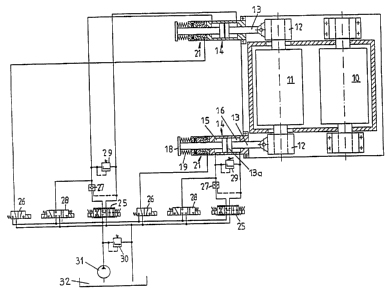
BRIEF DESCRIPTION OF THE DRAWINGS


Figure 1 is a schematic top plan view of a two-roll
crusher and a hydraulic circuit for controlling the motion of
the shiftable roll according to the invention.
5Figure 2 is a top plan view, on an enlarged scale, of a
detail of the structure shown in Figure 1.


DESCRIPTION OF THE PREFERRED EMBODIMENT


The two-roll crusher illustrated in Figure 1 has a
fixed roll 10 which is stationarily supported for rotation.
Opposite ends of a shiftable roll 11 are held in respective
bearing housings 12 coupled to piston rods 13 by means of
which the shiftable roll 11 is radially displaceable relative
to the fixed roll (countermember) 10. Each piston rod 13 is
part of identically structured respective double-acting
cylinders 14, each having two cylinder chambers (work
chambers) 15 and 16 which are separated from one another by a
slidable piston 13a affixed to the piston rod 13 and which
may be selectively charged with a hydraulic fluid. The
resulting pressure in the opposite work chambers varies the
axial position of the piston rod 13. As shown in Figure 2,

the piston rod 13 is passed through the bottom 17 of the
associated double acting hydraulic cylinder 14 and has, at
-- 7


- 2175879


its free end, a head 18 which is connected to the bottom 20
of a clamping head 21 with the intermediary of a spring 19.
The clamping head 21 has a setting piston 22 which is movable
against the force of a spring 23 situated between the setting
piston 22 and the bottom 20 of the clamping head 21. When in
the relaxed, expanded state, the spring 23 locks the piston
rod 13 to the clamping head 21 by a wedging effect, whereas
in an axially compressed state the spring 23 is released from
the piston rod 13, so that the latter is shiftable relative
to the clamping head 21.
The cylinder chambers 15 and 16 as well as a clamping
head chamber 24 may be charged with hydraulic fluid.
Since the two piston rods 13 operate in synchronism and
are of identical construction, the mode of operation and
construction of the hydraulic circuit will be discussed below
in conjunction with a single piston rod 13 and the clamping
head 21 belonging thereto.
The position of the piston rod 13 may be set by
pressurizing the work chambers 15 and 16 by means of a valve
25 which establishes a hydraulic connection between a pump 31
which draws hydraulic fluid from a sump 32, and the work
chambers 15, 16. Before such an operation is effected, a
valve 26 is actuated which pressurizes the work chamber 24 of
the clamping head 21, whereby the clamping head 21 is
released from the piston rod 13 by compressing the spring 23.
-- 8

- 217~%7~


When the desired position of the piston rod 13 is reached,
the work chamber 24 of the clamping head 21 is depressurized,
whereby the spring 23 again expands and thus locks the piston
rod 13 to the clamping head 21 which lies against the outer
5 radial face of the cylinder 14 corresponding to the position
illustrated in Figure 1.
A check valve 27 ensures that an oil leakage-free
closing of the cylinder chamber lS is effected which is pre-
pressurized via a valve 28. The pressure is limited to a
10 maximum magnitude by a pressure limiting valve 29. If the
crushing forces exceed the set maximum pressure, hydraulic
fluid flows from the work chamber 15 through the pressure
limiting valve 29 into the work chamber 16, and, as a result,
the piston rod 13 is withdrawn into the cylinder 14, that is,
15 the piston rod 13 assumes its position approximately as shown
in Figure 2. In such a position the shiftable roll 11 has
greater clearance from the stationary roll 10 than the set
crushing gap. The clamping head 21 remains firmly in its
position relative to the piston rod 13 and thus has moved
20 away from the radial outer face of the cylinder 14. To reset
the desired clearance (crushing gap), the valve 25 is
actuated, whereby the pressure increases in the work chamber
15 of the cylinder 14 until the piston rod 13 has reached its
position shown in Figure 1 in which the clamping head 21
25 again abuts the outer radial face of the cylinder 14. During
g

2175873


renewed actuation the clamping head 21 remains in its closed
(locking) state. The settable pressure in the cylinder
chamber 15 may be regulated in a stepless manner by a valve
30.
The synchronous control of the two cylinders 14 and the
two piston rods 13 is effected in a conventional manner.
Additionally, in the cylinder chamber 15 the pressure may be
monitored by means of a sensor. If required, the cylinder
chamber 15 may be coupled with a non-illustrated accumulator
which has an adjustable biasing pressure for limiting the
maximum crushing force.
It will be understood that the above description of the
present invention is susceptible to various modifications,
changes and adaptations, and the same are intended to be
comprehended within the meaning and range of equivalents of
the appended claims.


-- 10 --

Dessin représentatif
Une figure unique qui représente un dessin illustrant l'invention.
États administratifs

Pour une meilleure compréhension de l'état de la demande ou brevet qui figure sur cette page, la rubrique Mise en garde , et les descriptions de Brevet , États administratifs , Taxes périodiques et Historique des paiements devraient être consultées.

États administratifs

Titre Date
Date de délivrance prévu Non disponible
(22) Dépôt 1996-05-06
(41) Mise à la disponibilité du public 1996-11-18
Requête d'examen 2003-04-07
Demande morte 2006-05-08

Historique d'abandonnement

Date d'abandonnement Raison Reinstatement Date
2000-05-08 Taxe périodique sur la demande impayée 2000-05-24
2001-05-07 Taxe périodique sur la demande impayée 2001-05-16
2005-05-06 Taxe périodique sur la demande impayée
2005-07-11 Taxe finale impayée

Historique des paiements

Type de taxes Anniversaire Échéance Montant payé Date payée
Le dépôt d'une demande de brevet 0,00 $ 1996-05-06
Enregistrement de documents 0,00 $ 1996-08-08
Taxe de maintien en état - Demande - nouvelle loi 2 1998-05-06 100,00 $ 1998-04-27
Taxe de maintien en état - Demande - nouvelle loi 3 1999-05-06 100,00 $ 1999-04-13
Rétablissement: taxe de maintien en état non-payées pour la demande 200,00 $ 2000-05-24
Taxe de maintien en état - Demande - nouvelle loi 4 2000-05-08 100,00 $ 2000-05-24
Rétablissement: taxe de maintien en état non-payées pour la demande 200,00 $ 2001-05-16
Taxe de maintien en état - Demande - nouvelle loi 5 2001-05-07 150,00 $ 2001-05-16
Taxe de maintien en état - Demande - nouvelle loi 6 2002-05-06 150,00 $ 2002-04-15
Requête d'examen 400,00 $ 2003-04-07
Taxe de maintien en état - Demande - nouvelle loi 7 2003-05-06 150,00 $ 2003-04-16
Taxe de maintien en état - Demande - nouvelle loi 8 2004-05-06 200,00 $ 2004-04-14
Titulaires au dossier

Les titulaires actuels et antérieures au dossier sont affichés en ordre alphabétique.

Titulaires actuels au dossier
KRUPP FORDERTECHNIK GMBH
Titulaires antérieures au dossier
FINKEN, WOLFGANG
Les propriétaires antérieurs qui ne figurent pas dans la liste des « Propriétaires au dossier » apparaîtront dans d'autres documents au dossier.
Documents

Pour visionner les fichiers sélectionnés, entrer le code reCAPTCHA :


Pour visualiser une image, cliquer sur un lien dans la colonne description du document. Pour télécharger l'image (les images), cliquer l'une ou plusieurs cases à cocher dans la première colonne et ensuite cliquer sur le bouton "Télécharger sélection en format PDF (archive Zip)" ou le bouton "Télécharger sélection (en un fichier PDF fusionné)".

Liste des documents de brevet publiés et non publiés sur la BDBC .

Si vous avez des difficultés à accéder au contenu, veuillez communiquer avec le Centre de services à la clientèle au 1-866-997-1936, ou envoyer un courriel au Centre de service à la clientèle de l'OPIC.


Description du
Document 
Date
(yyyy-mm-dd) 
Nombre de pages   Taille de l'image (Ko) 
Dessins représentatifs 1998-03-20 1 21
Abrégé 1996-05-06 1 25
Page couverture 1996-05-06 1 17
Description 1996-05-06 9 311
Revendications 1996-05-06 5 153
Dessins 1996-05-06 2 42
Description 2004-10-22 9 305
Dessins représentatifs 2004-12-07 1 13
Poursuite-Amendment 2004-10-06 1 26
Cession 1996-05-06 8 394
Poursuite-Amendment 2003-04-07 1 44
Poursuite-Amendment 2004-10-22 2 56