Note : Les descriptions sont présentées dans la langue officielle dans laquelle elles ont été soumises.
~ ~17 ~35~
20006
WO 95/13453 PCT/EP94/03730
INJECTION CABLE BOLT
The invention relates to an injection cable bolt,
particularly for mining) ~llnn~ n~ and: ~n~ L con6truction, as
well as for securing rock faces, which basically consists of a
cable made for instance of heavy duty synthetic or natural textile
yarns having a high-l L~8,iul~ hose as a core, ~uLL~urlded by a net-
like support mesh, and which can be provided with a securing
element and a sealing element formed by two segments which can be
fit ome over th2 other via conically shaped annular surfaces, as
well as with a connec~ion element outside the bore which is
arranged in a sleeve ~ur-Lvull~ing the cable.
The generic cable bolt is closer described in German
Patent 40 18 703. Such a cable bolt designed as an in~ection cable
bolt has the advantage of an adjusted bendability, and cnnAeqn~ntly
allows advant~eoll~::ly an application from narrow, hollow spaces, by
taking over a ~ LL r~l..",~ling traction force. Furthermore an
additional advantage arises from the possibility to provide such
bolts with a bigger length, to operate them in an ~LL- -1Y simple
and safe manner and in addition to insure a practical
transportation.
2176~1
20006
W0 95J13453 PCT/EP94/03730
A drawback characteristic to the generic ~ Ls of
in~ection cable bolts can be found in the described . --ir L,
The bolt ha6 a core ~uLLuul.ded by the cable and the cable is
~u~ l vuJ~ded by a support grid, and cable and grid are again
YuLlvu--ded by a protective jacket of synthetic material.
It has been found that during injection the protective
jacket makes sure that the injection material in6ide the jacket
produces an intimate cementing in the cable, but that the delivery
of the in~ection materi~l over the entire length of the injection
cable bolt is not possible to the desired extent. The protective
jacket is an i ~ - t for optimal injection. The support grid is
'-~dflefl in the cement closely to the cable within the jacket, but
due to the lack of the widening possibility does not constitute an
additional, i nfl~r-~nfl~n~ly supporting bracing element.
A further disadvantage of the inj ection cable bolt
described in the above-mentioned patent consists in the fact that
the connections of securing and connection elements at the opposite
cable ends are very complicated and are not attuned to the traction
forces to be transmitted through the cable. Also the sealing
element provided for sealing the bore, which consists of two
superimposable wedge elements, is in need of improvement, as shown
by practice, since no active sealing of the two elements is insured
2~763~1
.
20006
WO 95~13453 PCT/I:P94/03730
solely due to their sliding on top of each other as a result o~ the
pL d~S~UL ~ medium .
In opposition thereto it i5 the object of the invention
to cr~ate an injection cable bolt for mining, tunnelling and
nl ~ construction, as well as for securing rock faces, which
by avoiding the drawbacks of the 6tate of the art, can be used as
a simple injection cable bolt, as well as an ~ n~l~hle bolt which
malces an optimal injection possible and which can be ~ luced in a
simple and cost-effective manner.
This object is attained according to the invention due to
the fact that the securing element is connected with the cable end
by means of a shrinking ho6e, that the se~; L~ of the sealing
element are each built o~ two half-shells which can fit together,
whereby the segment facing the bore opening is cylindrically shaped
on the inside over its entire length, while the segment which is
~lid over it is cylindric~lly shaped on the outside, and the
segment which is slid over has on the inside two conically shaped
widened areas, pointing in opposite directions away from the cable,
and that the ~leeve, which can be rigidly cnnn~cted with the cAble
end through the shrinking hose or by cementing, surrounds the
connection element at least partially, and that the connection
element has a or tube c~n be inserted in the core. Alternately a
~1763~1
20006
wo 95/13453 PCT/EP94/03730
double-layered or multilayered securing element can be mounted on
the cable end.
A special advantage of the invention is to be found
primarily in the fact that the securing element, which can be
connected by means of a shrinking hose with the cable end pointing
towards the deepest area of the bore, has a roof-like cap with a
central point and at ;least lateral injection opPnin~c, whereby the
roof-like cap is provided with holding fingers PYroPrlln~ the
diameter of the bore and for instance arranged in a stellar manner.
The c5)nn-'r~ion of the cable end with the securing element forms a
traction-resistant connection, which makes it possible to set the
in~ection cable bolt to the traction force required ~or eYpansion,
im~ediately after its il.~Luduu~ion into the bore. The star-like
arranged holding fingers, which represent only one of the
- c, dig themselves into the bore wall, but leave enough
room Eor the distribution of the in; ection material through the
injection opPnln~c provided laterally in the securing element, 80
that it can pe~ L.Ite the bore beyond the roof-like cap. It is
conceivable to provide at least one central inj ection opening in
the cap, which can be closed for instance by a flap in the manner
of a valve.
2~ 76351
.
20006
Wo 95/13453 PCT/EP94/03730
Further a particular advantage consists in the design and
arrA, L of the sections forming the sealing element. The
individual sections cal~ e~lch be ~ F"d of half-shells, which are
connectable in the manner of snap-buttons via cog connections, and
which in addition can also be ~ - ecl. The half-shells, which in
addition have cogs engaging in the cable on the inside for local
anchoring, being easy to a6semble, can be mounted in a simple
manner at any desired location of a cable bolt. The section which
can be slid over the fixable section has a particularly
advantageous design. The outer side directed towards the bore i8
cylindrically shaped, while as already mentioned, the inside of
this section has two opposite, conical extensions. With one of
this conical extensions, which faces the other section, the wedge
pushed by the injection medium slides over the lower wedge, thereby
~nhAn~1n~ the sealing effect. Since the slide-on section of the
sealing element is made of a 60fter material than the section
affixed to the cable and the injection medium penetrates the
conical extension under high ~resDuLt:, the wedge is pressed against
the bore walling, thereby completely se~ling off the bore, whereby
at corrf~p~n~l; r~ locations an additional toothing engages in the
bore walling. In order to make possible the escape of the air
, ~ssed during injection from inside the bore, it is possible to
provide the Dections of the sealing element with outer venting
slots, running in the direction of the cable.
. 21~3~1
20006
W0 95/13453 PCT/EP94/03730
Fur~h- L~: it proves to be ~ L. -ly advantageous within
the rL JLk of the invention when th~ cable end pointing towards
the bore opening, or located outside the bore, iB provided with a
sleeve in the form of a shrinking hose, or according to a further
~ --;r ~, can be provided with a jacket which can be connected
with tl~e cable end in an t:X~L~ ly traction-resistant manner.
For the execution of an injection cable bolt as a pure
in~ection bolt it is suitable to provide the connection element
with a threading or a rApid action cOI.rl 1 n~ . This can be done by
means of a shrinking hose, whereby the shrinking hose ~.ULL.~UIId8 at
least partially the cable end and the connection element. In order
to use such an injection cable bolt as a tension rod it is
advantageous to cement the cable end in an inner, e.g. rou~h~n~d
jacket, 80 that a tie plate can be slid on and a bracing nut can be
screwed onto it. In all ;: _-ir ~8 the connection element is
connected with a metallic or plastic tube, which is at least
partially introduced in the core inside the cable.
The core inside the cable is a high-pressure hose adapted
to the respective injection pressure, which can be provided with an
integrated support mesh, so that its cross section is not narrowed
while the cable is braided around the core during manufacturing.
~p~n~lin~ on the in~ection to be performed, it is possible to make
217~3~1
20006
wo 95/13453 PCT/EP94/03730
the core inside the cable, over its entire length, without a
coLL~ n~ perforation or slot. Otherwi~e it is possible to
make the core, over its entire or partial length, with
perforations, respectively oponin~c.
DDrDn~n~ on the use of the cable, it can be made of
polyethylene, polyester, kevlar, aramide, nylon, glass fiber,
carbon, filaments in yarn or fiber form or of a mixture of the
mentioned materials, 80 that it has the desired carrying capability
or for instance the desired ductibility.
The cable interweaving can be single-layered or
multilayered, whereby the used yarn can be of different strength.
Fur~h~ different types of interweaving can be selected,
~lDrDnts;n~ on the ta8k to be performed. In order to insure the
propa~ation of the injection material over the entire bolt length,
it is suitable to produce the cable with COLL- rL~ n~ a mesh
width. Furth~ - ~ it is possible to reinforce the cable for
instance by weaving in metal wire, whereby at the same time an
antistatic behavior is achieved.
Within the rL JIk of the invention it is further
possible to 2~uLLuu~ld the cable with an outer fine ~ d teYture
layer for the purpose of limiting the injection material, in order
~C35~
20006
WO 95/13453 PCT/EP94/03730
to reduce excessive ~ Lion, e.g. in ~ractured loose rock.
Otherwise the cable can be provided with a thin outer membr~ne
de~tructible during injection, in order for instance to press
inwardly the construction ~oints which occur during the concrete
work in different layers.
Besides the antistatic design of cable and support mesh,
the cable bolts can also be designed based on various flame-
retardant fibers or with additional flame-retardant coatings.
Several ~ S of the invention are represented in
the drawing and are s~lhsP~uPntly closer described. I~ shows:
Figure 1 a section through an embodiment example of the
in~ection cable bolt of the invention, when
used as a pure injeQtion bolt,
Figure 2 21 section through the ;r -It example shown
in Figure 1,
Figure 3 an: 'i ~t example of the injection cable
bolt of the nvention as tension rod,
2~ 7635~
20006
~o 95/13453 PCT/EP94/03730
Figure 4 a section through a further ~ ;r ~ example
of the in~ection cable bolt of the invention
as tension rod,
Figure 5 a partial section through the end of injection
bolt,
Figure 6 an: ' ~;r l example for the design of the
connection element in cooperation with the
tube,
Figure 7 a section through an . ' - '; r 1, example of a
sleeve for a tension rod affixed to the cable
end,
Figure 8 & 9 two embodiment examples for a multilayered
cable with a perforated and a nonperforated
core .
The cable 2 used for different ~ ;r~ t examples of
inj ection cable bolts is represented in Figures 8 and 9 in two
multilayered: ~ ~a;r-~ts. The multilayered cable 2 is ~uLL~,u-,ded
by a support mesh 4 of synthetic or steel braiding and has a core
3, w~ich can be inserted with or without integrated support
2~7~3~1
20006
W0 95/13453 PCT/EP94/03730
braiding, with or without perforationg, regpectively op~nin~ 5.
The support mesh can ~e an interweaving of various yarns, to which
metallic threads are added for antistatic ~.IL~oses. In the section
through an: _-;r t example of an injection cable bolt in Figure
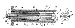
1, a cable bolt 1 is schematically represented in section. The
cable bolt l is arranged inside a bore in rock or mineral 13. The
cable bolt 1 consisting of a cable 2 with an inner core 3 has a
securing element 6 at the cable end 7 pointing towards the deepest
area of the bore, which in the represented: ;r--~t example i5
provided with lateral injection openings lO and a roof-like point
9. The 6ecuring element 6 is tightly connected with the cable end
7 by means of a shrinking hose 8. The securing element 6 has
holding fingers 11, which have a bigger cross section than the bore
12 and which engage in the bore walling during the retraction of
the cable bolt l.
Further the cable bolt 1 has a sealing element consisting
of two sections 16 and 17 which can slide on top of each other.
Each of the sections 16 and 17 consists of two half-shells 18,
which can be joined by means of cog cr~nn~ctions 19 in the manner of
snap-buttons and in addition can be cemented to each other.
The section 16 is fastened on the cable 2 at a
correspondingly provided location at the bore opening or inside the
217~3~1
20006
WO g5/13453 Pc~r/EPs4/03730
bore ~2, whereby the cogs 21 on the inside of the half-shell 18
press themselves into the cable, 80 that section 16 is immovably
arrested .
The section 17 of the sealing element 15, which can be
slid over ths section 16, is cylindrically shaped on its outside
~nd on the inside has two conical extensions 23, 24, pointing up
and dLown, respectively oppositely arranged in the longitudinal
direction of the cable. Advantageously the section 17 is made of
a 60fter material than section 16. Due to the pressure of the
injection mediu~, the section 17 slides over the section 16 and the
injection medium penetrates into the eYtension 24 and pre6ses the
section 16 with the corr~:p~n~lin~ toothing provided at the margins
in such a way against the bore walling, that a complete sealing is
achieved .
For connection of a hose duct for in~ection at the cable
end 25 protruding from the bore 12 a connection element 27 is
provided, which by means of a shrinking hose 26 partially
enveloping the shoulders 30 of the connection element 27, can be
rigidly connected to the cable end 25. The details inside the
c-~nnPct ion element 27 are closed illustrated in Figure 5 . The
embodiment example closer described in Figures 1 and 2 has to be
characterized as a pure inj ection cable bolt .
217~51
20006
WO 95/13453 PC~ Ps4/03730
Instead Or the shrinking hose 26, the cable end 25 can be
surrounded by a two-shell or multiple shell elenent for the
fixat~on of the tube 28 inserted in the core 3.
In the Figures 3 and 4 : o~ of an inj ection cable
bolt ~re L~ ;s_..Led, which have to be characterized as tension
rods. The ~ t example of an injection cable bolt shown in
Figure 3 deviates from the embodiment example in Figur~ 1, in that
the cable end 25 which i~ outside the bore 12 is arr~nged in a
jacket 36 d~siqn~d as a sleeve 26. The jacket 36 which can be
made, among others, of metal or plastic material, has a threading
39 on the outside and makes poscible for a tie plate 40 on the one
hand to slide on top, and on the other hand makes possible the
bracing of the tie plate 40 by means of the bracing nut 41. The
anchor tie 40 has a spherical cap 42 and the bracing nut 41 has a
rounding 43 ~ L'~ 51nq with the recess 42. Further dQtails of
this embodiment example are illustrated in Figures 6 and 7.
In Figure 6 it is indicated that the connection element
27 is connected with a tube 28 which can at least partially be
introduced into the core 3, and which furthermore is 2.u~ u-~ded by
a wedge 35 with a threading 38. Thi~ wedge can be screwed into an
opening of the jacket 36 and braces the cable 2 inside the jacket
36. Arter the insertion of the tube 28 in the jacket 36,
12
217~3~1
20006
Wo 95/13453 PCT/EP94/03730
resp~ctively in the cable 2, the cable end 25 is intimately
cemented inside the jacket 36, through injection via an injection
opening 37. Inslde the connection element 27, which as already
mentioned can be provided with a threading 29 or a rapid cnnn~ct~orl
coupling, according to Figure 5 a cylindrical segment 31 and a
conically narrowing segment 32 are provided, whereby check valve 33
in tlle rorm of a lip seal is arranged between the end of the tube
28 and an annular plug 34 provided for safety. From the ~ a;r- L
example shown in Figure 5 it is 2180 clear that the tube 28 is
introduced into the core 3 and that the shrinking hose 26 ~uLL~ullds
the connection element partially in the area of chn~llnDr 30,
thereby creating a rigid connection.
In Figure 4 a further: 'i nt example of an injection
cable bolt designed as a tension rod is shown, wherein for the
integr~tion of the connection element 27 into the cable end 25 a
shrinking hose 26 is provided, and at a distance therefrom around
the cable 2 a further shrinking hose segment 44 is provided, and
that between the segments 26 and 44 a jacket 45 with a threading 39
is applied for instance through an injection die casting process,
by means of which the bracing of the tie plate 40 is insured by a
~_~inq nllt ~1.
217~351
20006
Wo 95/13453 PCT/EP9s/03730
The op~nin~ 5 in the core 3 shown in Figure 8 can also
be slots running in the longitudinal direction of the core. This
way during injection at first outward injection starts in the
deepest area of the boreEi, then due to the ~res~uLe buildup the
slots are sllhs~qn~ntly opened and an outward injection takes place
over the entire cable length.
2.1763~
20006
wo 95/13453 PCT/E:P94/03730
T.~ ~t oP Re~erenCe J~ ~~ l
cable bolt
2 cable
3 core
4 support mesh
op~n i n~
6 securing element
7 cable end
8 shrin]~ing hose
9 roo~-like point
op~n 1 n~q
11 holding f ingers
12 bore
13 rock
14 annular space
sealing element
16 section
17 section
18 hal~-shells
19 cog connections
toothing
2 1 cogs
22 venting slot
23 conical extension
5 ~
20006
W0 9S/13453 PC~/EP94/03730
24 conical extension
cable end
2 6 sleeve
27 connection element
28 tube
29 threading
3 0 shoulder
31 cyl indrical segment
32 conical segment
33 check valve
34 annular plug
3 5 wedge
3 6 j acket
37 injection opening
3a threading (wedge)
39 threading (outer)
tie plate
41 bracing nut
42 spherical cap for recess
4 3 round~ing
44 shrinking hose segment
4 5 ~ acket
16