Sélection de la langue

Search

Sommaire du brevet 2184080 

Énoncé de désistement de responsabilité concernant l'information provenant de tiers

Une partie des informations de ce site Web a été fournie par des sources externes. Le gouvernement du Canada n'assume aucune responsabilité concernant la précision, l'actualité ou la fiabilité des informations fournies par les sources externes. Les utilisateurs qui désirent employer cette information devraient consulter directement la source des informations. Le contenu fourni par les sources externes n'est pas assujetti aux exigences sur les langues officielles, la protection des renseignements personnels et l'accessibilité.

Disponibilité de l'Abrégé et des Revendications

L'apparition de différences dans le texte et l'image des Revendications et de l'Abrégé dépend du moment auquel le document est publié. Les textes des Revendications et de l'Abrégé sont affichés :

  • lorsque la demande peut être examinée par le public;
  • lorsque le brevet est émis (délivrance).
(12) Demande de brevet: (11) CA 2184080
(54) Titre français: ANTENNES HYPERFREQUENCE
(54) Titre anglais: MICROWAVE ANTENNAS
Statut: Réputée abandonnée et au-delà du délai pour le rétablissement - en attente de la réponse à l’avis de communication rejetée
Données bibliographiques
(51) Classification internationale des brevets (CIB):
  • H01Q 21/06 (2006.01)
  • H01Q 21/00 (2006.01)
(72) Inventeurs :
  • COLLINS, JOHN LOUIS FREDERICK CHARLES (Royaume-Uni)
(73) Titulaires :
  • FORTEL TECHNOLOGY LIMITED
(71) Demandeurs :
(74) Agent: SMART & BIGGAR LP
(74) Co-agent:
(45) Délivré:
(86) Date de dépôt PCT: 1995-02-24
(87) Mise à la disponibilité du public: 1995-08-31
Requête d'examen: 2002-02-21
Licence disponible: S.O.
Cédé au domaine public: S.O.
(25) Langue des documents déposés: Anglais

Traité de coopération en matière de brevets (PCT): Oui
(86) Numéro de la demande PCT: PCT/GB1995/000398
(87) Numéro de publication internationale PCT: WO 1995023440
(85) Entrée nationale: 1996-08-23

(30) Données de priorité de la demande:
Numéro de la demande Pays / territoire Date
9403752.0 (Royaume-Uni) 1994-02-26
9409692.2 (Royaume-Uni) 1994-05-14

Abrégés

Abrégé français

Selon l'invention, on forme une antenne hyperfréquence (10) à partir d'une pile d'éléments (14-22) généralement plans formant un réseau d'éléments en forme de cornets communiquant avec les guides d'ondes (38). Ces éléments (14-22) sont en plastique métallisé et présentent chacun une épaisseur globale constituée par une membrane d'épaisseur relativement faible, dotée (généralement par formation sous vide) d'une configuration ondulée.


Abrégé anglais


A microwave antenna (10) is formed from a stack of generally planar elements (14-22) forming an array of horns (12) communicating
with waveguides (38). The generally planar elements (14-22) are of metallised plastics. Each of these elements (14-22) has a given overall
thickness which is constituted by a membrane of relatively small thickness formed (typically by vacuum forming) into a corrugated shape.

Revendications

Note : Les revendications sont présentées dans la langue officielle dans laquelle elles ont été soumises.


CLAIMS
1. An antenna comprising a plurality of generally
planar members secured together in face-to-face
relationship to form an array of cavities and a
waveguide system, each cavity being in
communication with at least one waveguide channel,
each of the planar members having a given overall
thickness transverse to its principal plane, said
thickness being constituted by a membrane of
relatively small thickness formed three-
dimensionally in a generally corrugated fashion.
2. An antenna according to claim 1, in which each of
the planar members is a vacuum forming.
3. An antenna according to claim 2, in which each of
the planar members is formed by vacuum forming a
plastics material and thereafter metallising at
least one side of the vacuum formed material.
4. An antenna according to any preceding claim, in
which each of said membranes is continuous across
the whole area of the antenna.
5. An antenna according to any of claims 1 to 3, in
which the waveguide channel is partially defined
by one said membrane which is cut away to form
void spaces in areas of the membrane not
immediately adjacent the waveguide channel.
6. A method of manufacturing an antenna, comprising
forming a plurality of generally planar members,
each of the planar members having a given overall
thickness transverse to its principal plane, said

thickness being constituted by a membrane of
relatively small thickness formed three-
dimensionally in a generally corrugated fashion,
positioning the planar members in face-to-face
relationship to form an array of cavities and a
waveguide system, each cavity being in
communication with at least one waveguide channel,
and securing the planar members together.
5. A method according to claim 4, in which the planar
members are secured together by ultrasonic
welding .
6. A method according to claim 5, in which the mating
faces of the planar members are provided with ribs
or the like which fuse to form weld beads during
the ultrasonic welding.

Description

Note : Les descriptions sont présentées dans la langue officielle dans laquelle elles ont été soumises.

21 ~4080
WO 95/23440 1
21 " Mi ~- rowave ~ntF-nn;- ~ -
3 This invention relates to antenna6, partic~ r]y (but
4 not exclusively) planar antennas for receiving
5 microwave signal6 such as direct broadcasting by
6 satellite (DBS) signals.
8 There are known planar antennas comprising an array of
9 horns ~ ating with one or more waveguide systems,
10 and in which the horns and waveguides are formed from a
11 sandwich of moulded planar members. The planar members
12 may be plastics mouldings with electrically conductive
13 surfaces formed by metallisation. See for example my
14 published International Patent Applications WOB9/09501
and WO91/20109.
16
17 While antennas of the foregoing type have proved
18 successful, there ig a need for further i uv, L
19 with a view to ease of mass manufacture and reduction
20 in manufacturing cost.
21
22 Accordingly, the present invention provides an antenna
23 comprising a plurality of generally planar members
24 secured together in face-to-face relationship to form

Wogs/23440 ~ 1 840~0
an array of cavities and a waveguide 6ystem, each
2 cavity being in _ i ~ation with at least one
3 w~veguide channel, each of the planar members having a
4 given overall thirknaRs transverse to its principal
5 plane, said thirknr~ss being constituted by a membrane
6 of relatively small thirknr~sS formed three-
dimensionally in a generally co.Luy~ted fashion.
9 Preferably, each of the planar members is a vacuum
10 f orming .
11
12 Preferably, each of the planar members is formed by
13 vacuum forming a plastics material and thereafter
14 met~71iRin~ at least one side of the vacuum formed
15 material.
16
17 From another ~spect, the present invention provides a
18 method of manufacturing an antenna, comprising forming
19 a plurality of rJ~-nr~rAl ly planar members, each of the
20 planar members having a given overall thirkn"ss
21 transverse to its principal plane, said thirknr~ss being
22 constituted by a ` ~n~ of relatively 5mall th i rknr~c8
23 formed three-dimensionally in a generally corrugated
24 fashion, positioning the planar members in face-to-face
25 relatinn~hi~ to form an array of cavities and a
26 waveguide system, each cavity being in ~ i ration
27 with at least one waveguide channel, and securing the
2 8 planar members together .
29
30 In a preferred form of the invention, the planar
31 members are secured together by ultrasonic welding; for
32 this purpose the mating faces of the planar members may
33 be provided with ribs or the like which fuse to form
34 weld beads during the ultrasonic welding.
3S

~ 2~ 840~0
Wo sst23440 3 ~ E
Embodiment6 of the present invention will now be
2 described, by way of example only, with reference to
3 the drawings, in which:
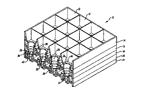
Fig. 1 i6 an isometric view, sectioned along a
6 Llhh~vt:Lr.e plane, of an antenna element according
7 to the present invention;
8 Fig. 2 shows part of Fig. 1 in greater detail, to
9 an enlarged scale;
Fig. 3 illustrates a preferred means used in
11 securing together parts of the assembly of Figs. 1
12 and 2;
13 Fig. 4 is a plan view illustrating the
14 co.~sLLu~;Lion of a modified form of waveguide
channel; and
16 Fig. 5 is an enlarged cross-sectional scrap view
17 on the line S-S of Fig. 4.
18
19 Referring particularly to Figs. 1 and 2, an antenna
element generally designated at 10 is in the form of a
21 4x4 array of receiving horns 12. In practice, the
22 element 10 would be assembled with like elements to
23 provide a larger array as a single antenna. The
24 antenna element 10 comprises five generally planar
members 14 - 22.
26
27 The first planar member 14 is formed to provide the
28 horns 12, each of which is of tAr~rin~ square section,
29 terminating in a lower wall 24 and circular tlpt~L Lul~:
26.
31
32 The second and third planar members 16, 18 together
33 define cylindrical cavities 28 aligned with the
34 circular apertures 26, and first closed, rectangular
section channels 30 extending along the length of the
,

21 ~80
Wo 9SI23440 P_ 1 .
antenna element 10. The cavities 28 terminate in a
2 plane partial end wall 32 defining a D-shaped slot 34.
4 The fourth and fifth planar members 20, 22 together
5 define bottom sections 36 to the horn cavities, and
6 second closed, rectangular section passages 38. Each
7 bottom section 36 has an upper part 39 ~,:VL r t,~vllding to
8 the D-shaped slots 34, and a lower part 40 forming an
9 open-topped channel ,_ n i cating with one of the
second passages 38.
11
12 The first ~hAnnP1R 30 c, icate with the cavities 26
13 by means of pas~as_yD 40 as indicated in Fig. 2.
14
15 Each of the planar members 14 - 22 is separately formed
16 by vacuum forming of a suitable plastics material.
17 T~rhniq~ of and materials for vacuum forming are well
18 known ~ and will not therefore be described in
19 detail herein. The walls of the horns, cavities and
20 ~hAnn~ have the effect of providing a corrugated
21 formation to each member, thus giving a reasonable
22 degree of rigidity which is increased when the five
23 members are secured together.
24
25 After vacuum forming, one side, as appropriate, of each
26 member is metallised in any suitable fashion, and thus
27 when the members are secured together the surfaces of
28 the horns, cavities and ~hAnn~ which are adjacent the
29 received microwave radiation are conductive metallised
30 surfaces . The ~ hAnn~ 30 and 38 thus act as
31 waveguides for differently polarised microwave signals
32 separated by the conformation of the cavities 26, as is
3 3 known ~ .
34
35 The f ive members may be secured together in any

2~ ~0~
wo gsl23440 r~
s
suitable manner. For example, they may be secured
2 together by adhesive. A preferred feature of the
3 present invention, however, i8 to 6ecure the planar
4 members together by mean6 of ultr;l~sn;r- welding. For
5 this purpose, as illustrated in Fig. 3, the mating
6 faces such as the lower face S0 of the first member 14
7 and the upper face 52 of the second member 16, are
B provided with ribs 54 which fuse to form cont
9 welded beads during ultrasonic welding.
11 Referring to Figs. 4 and 5, there is Lllustrated an
12 alternative cul".-Lu~;Lion of a moulded element 60 which
13 partially defines the wave guides, for example in
14 substitution for the element 22 in the above
: ~i . =
16
17 Fig. 4 shows a 12 x 12 array, but it will be understood
18 that the ~rrAn, L can be applied to any desired size
19 of array.
21 The element 60 is once again a vacuum forming in which
22 a single membrane of material is formed to provide
23 upper faces 62 and lower faces 64 joined by side webs
24 65 to define waveguide r~h~nn~l f; 66 . In this
25 embodiment, however, the upper faces 62 are defined
26 only as flanges in the vicinity of the waveguide
27 rhAnn~ 66, and elsewhere the material is cut away to
28 form void spaces 68.
29
30 This configuration is partic~ rly efficient and
31 results in a weight reduction of approximately 309~. In
32 addition, the particular design minimises the extent of
33 area which requires to be metallised.
3345

Dessin représentatif
Une figure unique qui représente un dessin illustrant l'invention.
États administratifs

2024-08-01 : Dans le cadre de la transition vers les Brevets de nouvelle génération (BNG), la base de données sur les brevets canadiens (BDBC) contient désormais un Historique d'événement plus détaillé, qui reproduit le Journal des événements de notre nouvelle solution interne.

Veuillez noter que les événements débutant par « Inactive : » se réfèrent à des événements qui ne sont plus utilisés dans notre nouvelle solution interne.

Pour une meilleure compréhension de l'état de la demande ou brevet qui figure sur cette page, la rubrique Mise en garde , et les descriptions de Brevet , Historique d'événement , Taxes périodiques et Historique des paiements devraient être consultées.

Historique d'événement

Description Date
Inactive : CIB de MCD 2006-03-12
Demande non rétablie avant l'échéance 2005-02-24
Le délai pour l'annulation est expiré 2005-02-24
Inactive : Abandon. - Aucune rép dem par.30(2) Règles 2004-02-26
Réputée abandonnée - omission de répondre à un avis sur les taxes pour le maintien en état 2004-02-24
Inactive : Dem. de l'examinateur par.30(2) Règles 2003-08-26
Lettre envoyée 2002-04-19
Inactive : Dem. traitée sur TS dès date d'ent. journal 2002-04-19
Inactive : Renseign. sur l'état - Complets dès date d'ent. journ. 2002-04-19
Exigences pour une requête d'examen - jugée conforme 2002-02-21
Toutes les exigences pour l'examen - jugée conforme 2002-02-21
Inactive : Grandeur de l'entité changée 2002-02-12
Modification reçue - modification volontaire 1996-11-20
Demande publiée (accessible au public) 1995-08-31

Historique d'abandonnement

Date d'abandonnement Raison Date de rétablissement
2004-02-24

Taxes périodiques

Le dernier paiement a été reçu le 

Avis : Si le paiement en totalité n'a pas été reçu au plus tard à la date indiquée, une taxe supplémentaire peut être imposée, soit une des taxes suivantes :

  • taxe de rétablissement ;
  • taxe pour paiement en souffrance ; ou
  • taxe additionnelle pour le renversement d'une péremption réputée.

Veuillez vous référer à la page web des taxes sur les brevets de l'OPIC pour voir tous les montants actuels des taxes.

Historique des taxes

Type de taxes Anniversaire Échéance Date payée
TM (demande, 3e anniv.) - petite 03 1998-02-24 1998-02-09
TM (demande, 4e anniv.) - petite 04 1999-02-24 1999-02-02
TM (demande, 5e anniv.) - petite 05 2000-02-24 2000-02-21
TM (demande, 6e anniv.) - petite 06 2001-02-26 2001-01-31
TM (demande, 7e anniv.) - générale 07 2002-02-25 2002-02-04
Requête d'examen - générale 2002-02-21
TM (demande, 8e anniv.) - générale 08 2003-02-24 2003-02-06
TM (demande, 2e anniv.) - petite 02 1997-02-24
Titulaires au dossier

Les titulaires actuels et antérieures au dossier sont affichés en ordre alphabétique.

Titulaires actuels au dossier
FORTEL TECHNOLOGY LIMITED
Titulaires antérieures au dossier
JOHN LOUIS FREDERICK CHARLES COLLINS
Les propriétaires antérieurs qui ne figurent pas dans la liste des « Propriétaires au dossier » apparaîtront dans d'autres documents au dossier.
Documents

Pour visionner les fichiers sélectionnés, entrer le code reCAPTCHA :


Pour visualiser une image, cliquer sur un lien dans la colonne description du document. Pour télécharger l'image (les images), cliquer l'une ou plusieurs cases à cocher dans la première colonne et ensuite cliquer sur le bouton "Télécharger sélection en format PDF (archive Zip)" ou le bouton "Télécharger sélection (en un fichier PDF fusionné)".

Liste des documents de brevet publiés et non publiés sur la BDBC .

Si vous avez des difficultés à accéder au contenu, veuillez communiquer avec le Centre de services à la clientèle au 1-866-997-1936, ou envoyer un courriel au Centre de service à la clientèle de l'OPIC.


Description du
Document 
Date
(aaaa-mm-jj) 
Nombre de pages   Taille de l'image (Ko) 
Dessin représentatif 1997-10-14 1 17
Revendications 1995-02-24 2 55
Dessins 1995-02-24 4 167
Description 1995-02-24 5 172
Abrégé 1995-02-24 1 57
Page couverture 1995-02-24 1 15
Revendications 1996-11-20 2 66
Rappel - requête d'examen 2001-10-25 1 118
Accusé de réception de la requête d'examen 2002-04-19 1 180
Courtoisie - Lettre d'abandon (taxe de maintien en état) 2004-04-20 1 175
Courtoisie - Lettre d'abandon (R30(2)) 2004-05-06 1 167
PCT 1996-08-23 9 354
Correspondance 1996-09-03 4 167
Taxes 1997-01-28 1 49