Note : Les descriptions sont présentées dans la langue officielle dans laquelle elles ont été soumises.
~ 218619~
Ra 11.13.95 95/145
TITLE OE THE INVENTION
System for tran6mitting electrical energY having at
least one underground, high-voltage electrical
conductor, and a method for producing such a system
BACKGROUND OF THE INVENTION
Field of the InYention
The invention is based on a system f or
10 transmitting electrical energy having at least one
underground, high-voltage electrical conductor
according to the preamble of patent claim 1. The
invention also relates to a method for producing such a
system.
Discussion of Back~round
Such a syste~ is preferably used in
conurbations, and usually contains high-voltage cables
which are laid in the ground and conduct electrical
20 energy from power stations, overhead lines or
transforming stations to substations in which high
voltage of, for example, 110 kV is transformed to
medium voltage of, for example, 10, 20 or 30 kV. In
rapidly growing urban agglomerations, in particular in
25 Asia, such a system cannot be set up or extended
without substantial i ~ - i 1 of elements of the
infrastructure, such as the traffic, supply of water
and gas and the disposal of sewage. This is so chiefly
because it is g~nPr~l ly nP- P~sArY when laying and
3 0 maintaining high-voltage cables to dig trenches, and
this very severely disturbs the inf rastructure and
substantially impairs its efficiency.
SUMMARY OF THE INVENTION
- Accordingly, one object of the invention as it
iS spe''i f i Pd in Patent claims 1 and 11 is to provide a
novel system of the type mentioned at the be~innin~
which is dist;n~ hpd by a high av~ hil ity~ is easy
~ ~ - 2 - 2186190 95/145
- to maintain and at the same time can be produced using
a method which when carried out at most slightly
impairs the infrastructure of a conllrhat; f~n
accommodating the system.
The system Arc-~rrl; nq to the invention is
distinguished in that c~ 1; rAted and vulnerable cable
connections are eliminated, and that only very slight
reacti~,~ p-._l losses occur. In addition, the
individual cable sections can be cooled particularly
effectively, and 80 an e~LL~ ly high current carrying
capacity can be achieved. Since the system is generally
laid several meters below the surface of the earth,
eleeLl~ gnPtic interference fields scarcely penetrate
to the outside, and the system is t e~VeL largely
protected against act8 of vAn~lA 1 i ~
It is part;f~lllArly advantageous that the system
can be ~loduced in a method in which distllrhAn~ e of the
infra~LLu. Lule: already present is largely avoided. The
tearing up and disrl Al . L of traf f ic arteries, the
interruption of already existing r;r~1;ne~ and cabling,
and the excavation of cable trenches and cable shafts
are eliminated virtually ~ le~Ply. ~ LeoveLl it is
possible, as the case may be, for the system according
to the invention to be produced in a single process
and, at the same time, for further c ~ lta of the
infrastructure, such as sewage pipes, to be produced as
well .
BRIEF DESCRIPTION OF TME DRAWINGS
A more complete apprP~; Al'; on of the invention
and many of the attendant advantages thereof will be
readily obtained as the same becomes better understood
by referenoe to the following detailed description when
c~n~i~Pred in connection with the Al - ,-nying
drawings, wherein:
Figure 1 shows a block diagram of an ~ ; L,
designed as a ring, of a system A<cr~r~lin~ to
the invention having an underground gas-
_ _ _ _ _ _ _ _
3 _ 2 1 8 6 1 9 0 95/145
- insulated cable and substations having
installation points,
Figure 2 shows, in a greatly ~ ; ecl
representation, a part of the system in
accordance with Figure 1 which has two
sections of the gas-insulated cable and one
of the installation points,
Flgure 3 shows, in a pe- Dy~;l ive view, a part of a
gas-insulated cable, r1P~; ~nPd with three
phases, in the region of the installation
point in accordance with Figure 2, and of a
cooling device preferably c~ln(~ f i n~ air or
water as coolant,
Figure 4 shows, in a - p~lD~e~;l ive view, a part of a
gas-insulated cable, ~PSi gnPd with a
plurality of phases, in the region of the
installation point in accordance with Figure
2, and of a cooling device which conducts an
insulating gas from two phases of the gas-
insulated cable as coolant,
Figure 5 shows, in a ~ tic ~ ese--l.ation, a
plan view of a gas-insulated cable, ~3e~ nPd
with three phases, and an additional pipe in
the region of the installation point in
accordance with Figure 2, in which two phase3
each of the gas-insulated cable or the third
phase of the gas-insulated cable and the
additional pipe are respectively assigned to
a cooling device in accordance with Figure 4,
3 0 and
Figure 6 shows, in a r~i~j tic representation, a
plan view of two gas-insulated cables,
respectively r~P~i~npd with three pha3es, in
the region of the installation point in
accordance with Figure 2, in which two phases
- each of the two gas-insulated cables are
respectively ~si~nPd to a cooling device in
accordance wlth Figure 4.
. _ . _ . .. . . . _ _
21861~0
_ 4 _ 95/145
DESCRIPTION OF T~E E'K~ ~;IJ EM;30DIMENTS
Ref erring now to the drawings, wherein like
reference numerals designate identical or corresponding
5 parts throughout the several views, the system
according to the invention shown in Figure 1, which is
designed as a ring, has an undt:lyL~ u.ld gas-insulated
cable 1. In a substation 2 of the system, electrical
energy is tapped from an extra-high-voltage cable 3,
10 ~ s;~n~ for 400 kV, for example, stepped down to a
high voltage of, for example, 110 kV, and fed into the
gas-insulated cable 1 ~ i qn~.~l f or this voltage . The
gas-insulated cable 1 has ulldeLyLoulld cable sections of
which, for reasons of clarity, only four cable sections
11, 12, 13, 14 are provided with reference numerals.
Two mutually abutting cable sections each, for example
the cable sections 11 and 12, are accessible from the
outside and can be operationally interconnected. The
accessibility from the outside can advantageously be
provided at a network junction point or a substation 4
(having an installation point) at which the line
voltage of 110 kV carried in the cable sections 13 and
14 is stepped down to a medium voltage of, typically,
10, 20 or 30 kV, but can also be arranged at a point 5
which iB ;~rcr~;hle to field staff and at which two
cable sections, f or example the cable sections 11 and
12, are directly interconnected.
An arrangement of the two cable sections 11 and
12 which is typical of the system can be seen in Figure
2. It can be seen that the cable sections 11, 12 are
laid below the surf ace 6 of the earth and are
accessible from the outside at the point 5. Also
provided at the point 5 is a device 7 for feeding at
least one of the two cable sections 11, 12 with
coolant. ~l'he cable sections 11, 12, 13, 14 are
typically approximately 300 to 500 m long and are
generally buried apprr7ri~-t~-ly 10 m below the surface 6
of the earth. This reliably prevents any negative
_ 5 _ 21861a() 95/145
influence on the environment, in particular through the
leakage of ele~:LL- ~nP~ir interference fields.
The gas-insulated cable 1 can be t1-o~; gn~d with
one or more phases or as a double cable. In each case,
the cable 1 has an electrical conductor 8, visible f rom
Figure 3, for sxample, which is arranged, mounted on
insulated supports 9, in a ri r.ol i n~ 10 . The ri r~l i n~ 10
is f illed with an insulating gas, such as SF6, f or
example, at a pressure of up to a f ew bars, and may be
_ ~3e~1 of metal such as Alllm;nllm or steel, for
example, or, as the case may be, conductively coated
plastic such as polyethylene, for example. The gas
space can be monitored for tightness in a simple way by
means of a pressure sensor. As can be seen in Figure 3,
the electrical conductor 8 can be arranged on the axis
of the ri rPl i n~ 10 . If the gas-insulated cable 1 is
designed - a3 l~yrese"Led in Figure 3 - with three
phases, the electrical conductors assigned to the two
other phases are arranged centrally in further
rir~lin~3 10' and 10' ' which are routed parallel to one
another and to the pir~l in~ 10. In the case of a
multiphase, for example three-phase, system, the phase
conductors can also be arranged in a 8ingle pi r~l i nQ
while complying with the pr~Srri h--d insulation
spacings . E ach ri r~l i n~ 10 or 10 ~ or 10 ' ' is assembled
from pipes 101, 102 or 101', 102' or 101'', 102'' which
can be int,:L-;~.,ne~l ed at the installation point 5.
Compartmentalized insulators 103 or 103 ~ or 103 ' '
prevent the exchange of gas between mutually abutting
pipes 101, 102 or 101', 102' or 101' ', 102~ ' .
The cooling device 7 provided at the
installation point has pipes 71 and 72 which serve to
Arc~ ~-te coolant such as, in particular, air or, for
example, water and are routed parallel to the ri r~l i n~q
10, 10 ' and 10 ~ ' . The pipeJ 71 and 72 are situated one
behind another on a common axis 73 and are :~rrAng~rl at
approximately the same distance from the rirf~l in~:3 10~
10 ~ and 10 ~ ~, which are preferably located at the
corners of an equilateral triangle. The ri r ~l i nes~ 10 ~
- 6 - 21 86~ 90 95/145
- 10', 10' ' typically have diameters of 30 to 50 cm.
Their mutual spacing is generally 20 to 100 cm. The
pipes 71 and 72 are fl~ nP~ bent in the region of the
installation point 5 and are routed upwards in the
5 vertical direction out of the system af ter the bend .
Coolant, for example air, is blown into the pipe 71
using a conveying means (not marked) and is removed
f rom the pipe at the next installation point by means
of a further conveying means. Thi3 further conveying
10 means corresponds to the conveying means represented at
the upper end of the pipe 72. On its path through the
pipe 71, the coolant extracts from the heated earth
surrounding the phase conductors heat which is
dissipated directly to the environment at the
15 installation point . The only energy required f or the
cooling function serves merely to operate the conveying
means .
The r;rolin~ 10, 10', 10'- and the pipes 71
and 72 are ~ n~d such that each of the r; r~; n~
20 can also serve to carry the coolant and each of the
pipes 71 and 72 can also serve to Ar- -~Ate one of
the current phase conductors. If, for example, one of
the phases, for example the phase provided in the
rir~;n~ 10, is defective, the pipes 71 and 72 can be
25 joined at the installation point, and an electrical
conductor mounted on insulated supports can then be
inserted into the pipeline thus formed, forming a
nondefective phase in the process. The Pirl~ in~ 10
i~s~;~nPd to the defective phase is then r~ n~d to
30 correspond to the pipes 71 and 72 and then serves to
carry the coolant. In addition, it is pos~ihlf~ as the
case may be, to route a return conductor pArAl 1 f~l to
the r;r~l;n~ 10, 10', 10'', and/or it i8 al80 pos~ihl--
to provide electrical phase conductors, routed
35 parallel, of a second gas-insulated cab;- carrying a
second multiphase current. '
Instead of an open cooling system having air or
water as cooling meang, it is also ros~ihll- to use A
closed cooling system having the insulating gas
' ~ _ 7 _ 218619[~ 95/145
- provided in the cable sections 11, 12, r ~ Or3i ~s
of such cooling systems can be 3een in Figure6 4, 5 and
6. In the case of the said: ' o~i Ls, the cooling
system has at the installation point heat exchangers
5 74, 75 which are re3pectively connected via vertical
pipe sections (not designated) to rirr~l;nPc, for
example 10 and 10 ~, a33igned to the two phase
conductors. First conveying means 76 produce
circulation of the insulating ga3 from the heat
exchanger 74 through the pipe 101- of the rirPlinP 10'
to a heat C~Y' h~nrJPr which is arranged at the next
installation point (not shown) and c.~LL~D~ollds to the
heat PY~ hAnrJ~r 75, and from there through the pipe 101
of the pipeline 10 back to the heat exchanger 74 (cf.
15 the arrows illustrated in Figure 4 ) . The heat absorbed
during circulation through the pipe 101 i3 removed in
the heat exchanger 74, for example by mean3 of blowers
77. In a corresponding way, the heat absorbed during
circulation through the pipe 101- is removed in the
20 heat exchanger (not shown) corresponding to the heat
exchanger 75.
In the: -~; t of the closed cooling 3ystem
according to Figure 5, the pipes 71 and 72 and the
P;r~; nP 10 ' ' ~ which ~- '~te a third phase
conductor and is assembled from pipes 101 ~ ~ and 102 ~ ~,
are further represented in addition as a supplement to
Figure 4. In the case of this cooling device, the
r;rel;nP 10' ' containing the third phase, or the pipe
101' ' is connected to the pipe 71 via a heat PYr h;~ngPr
78. For the three phases, there is thus a need per
cable section, for example 11, for two closed cooling
circuits, of which one is routed in the pipes 101 and
101- ~s;~ned to two pha3e3, and the other i3 routed in
the pipe 101 ~ ~, ~si~JnP~l to the third pha3e, and the
pha3e-free pipe 71.
- The : ' - '; t. of the clo3ed cooling system
according to Figure 4 which is represented in Figure 6
is intended f or cooling a system according to the
invention which is ~1PC; rJnPd as a double cable and
21861qO
- 8 - 95/145
respectively has three phase conductors. The three
phase conductors of the two cables are arranged in
rir~l;ne~ 10, 10', 10~' or 20, 20', 20'' with the pipes
101, 102, 101, 102', 101'', 102'' or 201, 202, 201',
202, 201' , 202 ' ' . In this ~ ' -'i L, a closed
cooling circuit having a heat exchanger 74, 78 or 79 i8
respectively A~sign~rl to two phases. An additional pipe
provided for cooling purposes, such as the pipe 71 or
72, can be eliminated.
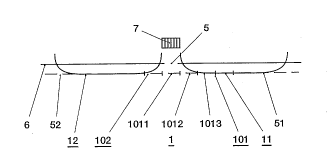
With reference to Figure 2, the system
according to the invention can be ~Luduced in a simple
way by ~lr; 11 i n~ at least two prerl~ nAntly horizontally
routed, underground ducts 51, 52 before the production
of the operational connection at the installation point
5 . At least one of the two cable sections, f or example
the cable section 11, is produced by gas-tight
connection of comparatively short, for example 8 - 10 m
long, pipe sections 1011, 1012, 1013. In this case, for
example, the pipe section 1012 and, in a coLL~~y ~ rlin~
way, the pipe section 1013 already connected in a gas-
tight fashion to this section, are pushed 80 deep into
the duct 51 that all that remains exposed at the
installation point 5 is the end of the pipe section
1012 facing the installation point 5. The pipe section
lO11 is then connected in a gas-tight way to the
initially still exposed end of the pipe section 1012.
The pipe thus formed is pushed into the duct 51 until
only the end of the pipe aection 1011 remains exposed.
After the entire pipe 101 of the cable section 11 has
been ~Luluced in this way, the electrical conductor,
which is held by slidably ~le~ j qn~d insulated supports,
i8 inserted into the laid pipe. Compartmentalized
insulators such as, for example, the compartmentalized
insulator 103 (Figure 3) are installed at the ends of
the pipe, for example 101, Aq~iqn~ to the cable
section, for example 11.
Alternatively, the pipe sections inserted into
th- prefabricated, und~ly uul.d duct can already
~ 218619~
_ 9 _ 95/145
- acc: ~3Ate the electrical conductors, held by
insulated supports, bef ore ga3-tight connection .
In general, the duct 51 or 52 routed
Undt~IyLuulld can be produced by drilling. The pipe
5 sections, f or example 1012, can be inserted into the
duct 52 by the exertion of pre8sure. The installation
point 5 must be dimensioned sllffi~;Pnt large to be able
to guide the pipe sections to the openings of the ducts
51, 52 and to insert them into the ducts.
The ducts 51, 52 need not be routed straight;
they can also - as is to be seen in Figure 2 - be of
partially bent design . The tlr; 1 1; n~ device can then be
positioned on the surface of the earth. In this case, a
hole is initially drilled through the surface of the
15 earth and is as a rule initially guided prf~l n~ntly
vertically. The section guided pre~l ~ nAntly vertically
f or at most a f ew meters is ad j oined by a section,
extending in a bent f ashion, of several meters which
finally merges into a section a few hundred meters long
20 which extends pr~rl ; n;tntly horizontally. This
horizontally extending section can be adjoined in turn
by a section of bent design and is passed through the
surf ace of the earth at an external installation point
5, or the horizontally extending section can open into
25 an installation point 5 arranged underground, a~
represented by dashes in Figure 2.
It is particularly advantageous when use is
made, for the purpose of A~-_ 'Ating the pipe, of a
duct which is guided underground and is already used
30 for a different purpose, since flr;ll;n~ work is then
avoided. It is particularly advantageous if the duct is
filled with a shock-absorbing liquid such as, for
example, sewage. The sewage supports the tube in a
~hock Ahs~rh;n~ fashion. Seismic forces caused by
35 earthqua} ~s are absorbed by the sewage surrounding the
pipe on all sides, with the result that no radial
forces are exerted on the pipe. Since the sewage is at
earth potential, the pipe holding the electrical
conductor is always kept at a defined potential.
- lo 2 ~ 86 1 9 0 95/145
- Obviously, numerous '; ~; r~tions and
variations of the present invention are possible in
light of the above te~rh;n~s. It is therefore to be
understood that within the scope of the ~rp~n~ d
5 claims, the invention may be practiced otherwise than
as sp.orif;r~lly described herein.