Sélection de la langue

Search

Sommaire du brevet 2187947 

Énoncé de désistement de responsabilité concernant l'information provenant de tiers

Une partie des informations de ce site Web a été fournie par des sources externes. Le gouvernement du Canada n'assume aucune responsabilité concernant la précision, l'actualité ou la fiabilité des informations fournies par les sources externes. Les utilisateurs qui désirent employer cette information devraient consulter directement la source des informations. Le contenu fourni par les sources externes n'est pas assujetti aux exigences sur les langues officielles, la protection des renseignements personnels et l'accessibilité.

Disponibilité de l'Abrégé et des Revendications

L'apparition de différences dans le texte et l'image des Revendications et de l'Abrégé dépend du moment auquel le document est publié. Les textes des Revendications et de l'Abrégé sont affichés :

  • lorsque la demande peut être examinée par le public;
  • lorsque le brevet est émis (délivrance).
(12) Brevet: (11) CA 2187947
(54) Titre français: ETIQUETTE D'ALARME ANTIVOL
(54) Titre anglais: ALARM TAG
Statut: Réputé périmé
Données bibliographiques
(51) Classification internationale des brevets (CIB):
  • G08B 13/14 (2006.01)
  • E05B 73/00 (2006.01)
  • G08B 13/06 (2006.01)
  • G08B 13/24 (2006.01)
(72) Inventeurs :
  • HOLMGREN, BERTIL (Suède)
(73) Titulaires :
  • MW TRADING (UK) LTD. (Royaume-Uni)
(71) Demandeurs :
  • MW INTERNATIONAL LTD. (Royaume-Uni)
(74) Agent: BORDEN LADNER GERVAIS LLP
(74) Co-agent:
(45) Délivré: 2003-07-01
(86) Date de dépôt PCT: 1995-04-11
(87) Mise à la disponibilité du public: 1995-10-19
Requête d'examen: 2001-12-19
Licence disponible: S.O.
(25) Langue des documents déposés: Anglais

Traité de coopération en matière de brevets (PCT): Oui
(86) Numéro de la demande PCT: PCT/SE1995/000385
(87) Numéro de publication internationale PCT: WO1995/027959
(85) Entrée nationale: 1996-10-15

(30) Données de priorité de la demande:
Numéro de la demande Pays / territoire Date
9401218-4 Suède 1994-04-12

Abrégés

Abrégé français

Une étiquette d'alarme antivol se compose de deux parties dont l'une (12) est munie d'une épingle (13) fixée sur ladite partie (12) destinée à être placée sur une face d'un produit (11), l'épingle traversant le produit et s'enclenchant sur l'autre partie (10) se présentant contre la face opposée du produit. L'une des parties comporte un circuit déclenchant, soit un dispositif d'alarme situé dans l'autre partie, soit un dispositif d'alarme externe lors de l'entrée ou de la sortie de l'étiquette d'alarme antivol par rapport à un champ externe. En outre, l'une des parties comporte un élément contact (26) actionnant le dispositif d'alarme. Une première position repos de l'élément contact correspond au silence du dispositif d'alarme. Mais par construction, cette première position peut être transformée au moyen de la fixation à épingle en une seconde position repos (26') permettant d'actionner le dispositif d'alarme en cas de tentative de désolidarisation des deux parties de l'étiquette d'alarme antivol.


Abrégé anglais


Alarm tag comprising two parts one
of which (12) is provided with a pin (13)
attached to said one part (12) to be located
on one side of a product (11) with the pin
extending through the product into locking
engagement with the other part (10) located
on the opposite side of the product. One
of these parts has means for activating
an alarm device in said other part and or
an external alarm device by the alarm tag
being carried into or out of an external
field. Furthermore, one part comprises a
contact element (26) operatively related to
said alarm device or a second alarm device,
said contact element normally being in a
first position in which the alarm device is
silent but being constructed to be switched
via the pin attachment to a second position
(26') in order to activate the alarm device
at attempt to separate the two parts of the
alarm tag.

Revendications

Note : Les revendications sont présentées dans la langue officielle dans laquelle elles ont été soumises.


6
CLAIMS:
1. Alarm tag for a product comprising:
a first part to be located on one side of the product;
a pin attached to the first part, the pin extendible
through the product when the first part is located on said
one side of the product;
a second part to be located on the opposite side of the
product for locking engagement with the pin of the first
part;
means providing locking engagement between the pin and
the second part;
an alarm device in said first part, the alarm device
being electronically activated;
a power source for said alarm device in said first part;
an electronic control circuit in said first part for
controlling interconnection of the power source and the
alarm device;
a conductive first contact element integrally connected
with the electronic control circuit; and
a conductive second contact element wherein the second
contact element is a bistable contact element in the first
part, said bistable contact element having a first stable
position which is the normal position thereof and in which
the bistable contact element is separated from the first
contact element, the electronically controlling
interconnection thereby being interrupted and the alarm
device being silent, and said bistable contact element
having a second stable position in which the bistable
contact element engages the first contact element, the
electronically controlling interconnection thereby being
closed and the alarm device being activated, the pin being
operatively connected with the bistable contact element to
switch momentarily the bistable element from the normal
first stable position to the second stable position thereof
in order to activate the alarm device at attempt to separate


7
the first and second parts of the alarm tag when in locking
engagement with each other.
2. Alarm tag according to claim 1 wherein the bistable
contact element comprises a bistable spring washer.
3. Alarm tag according to claim 1 wherein the bistable
contact element is arranged to be switched to the second
stable position via the attachment of the pin.
4. Alarm tag according to claim 1 wherein the first part
foams a resiliently deformable wall, and wherein the pin and
the bistable contact element are operatively connected with
said wall.
5. Alarm tag according to claim 4 wherein the deformable
wall forms a bulge and wherein the pin is attached to the
bulge.
6. Alarm tag according to claim 5 wherein the bistable
contact element comprises a bistable spring washer which
forms an aperture therein, and wherein the bulge of the
wall forms an annular groove, the edge portion of the
spring washer around said aperture being received in said
annular groove.
7. Alarm tag according to claim 4, wherein the first part
forms a space receiving the alarm device, the resiliently
deformable wall forming an outside wall of said space.
8. Alarm tag according to claim 7 further including a
circuit board inserted into the space, the electronic
control circuit being included in the circuit board, and
contacts on said circuit board for co-operation with the
bistable contact element located between the circuit board
and the resiliently deformable wall.


8
9. Alarm tag according to claim 1 wherein the electronic
control circuit is constructed to be triggered to the second
stable position of the contact element for continued
activation of the alarm device.

Description

Note : Les descriptions sont présentées dans la langue officielle dans laquelle elles ont été soumises.

21 87947
WO 95/27959 P~ Dr '.
Al ARM TAG
The invention relates to an alarm tag comprising two
parts one of which is provided with a pin attached to said
one part to be located on one side of a product with the
pin extending through the product into locking engagement
with the other part located on the opposite side of the
product, said one part having means for activating an alarm
device in said one part.
Existing alarm tags are of one or the other of two
types. Either the alarm device is located in the alarm tag
80 that an alarm will be emitted f rom the alarm tag at
thef t of the protected product, or means in the alarm tag
affect an external alarm device so that an alarm is emitted
externally at theft. In both cases said one part has a
completely passive element and comprises a head on the pin,
most frequently of plastics, the only purpose of which is
to l-~~;rt~;n the alarm tag mechanically on the product. In
both cases there are deficiencies regarding the security
against theft to be afforded by the alarm tag. Thus, it is
possible to remove the alarm tag from the protected product
by cutting off the pin or by crushing the plastic head, and
Z5 if this is done no alarm will be given unless either the
pin is withdrawn from the alarm tag or the alarm tag is
carried into or out of an external f ield . It is thus
possible to remove the alarm tag and then walk out carrying
the product from the area protected again8t theft without
an alarm being given.
The purpose of the invention is to provide an alarm
tag which improves the security against unauthorized
removal from the product to be protected against theft by
means of the alarm tag, and for this purpose the alarm tag
of the kind ref erred to above has obtained according to the
invention the characterizing features of claim l.
RECrIFIED SHEET (~ULE 91)

2~&~7
WO g5/2795g r~ L .

In order to explain the invention in more detail
reference is made to the accompanying drawing which
discloses an illustrative ~ Irllr t and wherein
FIG. l is a side view of an alarm tag attached to a
product which is shown f ragmentarily in cross
section, and
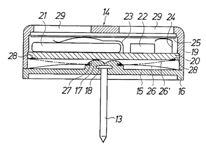
FIG. 2 is an enlarged cross sectional view of that
part of the alarm tag which comprises a pin and a
head.
In FIG. l there is disclosed an alarm tag which
comprises a first part lO rr~nt~;n;n~ means for~ initiating
alarm from an alarm device which either is built into this
part or consists of an external alarm device. The alarm is
initiated when the alarm tag is carried out from a defined
area in a department store or a shop due to the fact that
the alarm tag then, at the exit fr~om said area, will leave
of an electromagnetic or electrostatic ~ield maintained in
said area, or is carried through such a f ield maintained
between bows located one at each side of ~he exit passage.
This part of the alarm tag can be.of any existing known ~
construction. Part lO is applied to one side of a product
ll. The alarm tag aleo comprises a second part 12
consisting of a pin 13 with a head 14 said head being
applied to the opposite side of product ll~ with the pin
extending through the product and being attached to part
lO. The att~rhm~nt is such that the parts cannot be moved
apart for removal of the alarm tag from the product unless
the attachment is operated magnetically or merhiln; c~l ly in
a special device at the site where the product is to be =
paid, according to a well-known technique applied in
connection with alarm tags.
The invention is based on the knowledge that each
attempt to move the two parts of the alarm tag apart or to
cut of the pin by means of a cutter or the like which is
inserted between the parts causes deforming forces on the

2 1 ~79~7
~ W0 95l2?959 P~ ~

parts. This i3 utilized according to the invention in order
to emit an alarm from the alarm tag when such deforming
forces act on the alarm tag. Instead of being constructed
in a known manner as a plastic head the only purpose of
5 which is to r~;nt~;n in co-operation with part 10 and pin
13 the alarm tag on the product, head 10 c~nt~1n~ according
to the invention an ~ ry alarm device in addition to
the alarm device provided in part 10 or ~t~rn~l ly, said
ry alarm device being constructed to be activated ab
lO soon as deforming forces occur in part 12.
Part 12 is shown in detail in FIG. 2 and as can be
seen head 14 comprises a bottom plate 15 which hab for
example circular shape. Said plate preferably is made of
plastics of such kind that the plate iB impact resistant
l5 and elastically deformable and also can be fused. A
suitable material is for example polycarbonate. The plate
has a downwardly ~ t~n~l;ng- peripheral rim 16 which stiffens
the plate at the periphery, and a central bulge 17 in which
the pin is attached at a head 18 formed on the pin. A
20 cylindrical cover 19 is fused to plate 15 and includes a
circuit board 20 with a battery 21 and an eIectronic
circuit 22 located on said board. Contact springs 23 and 24
m~;nt;~ln electric connection between the electronic circuit
and the battery/ respectively, and a sound membrane 25.
25 This electronic alarm device can be constructed according
to principles which are well known in connection with
miniatyrized electronic alarm device8 and therefore will
not be described in further detail.
A bistable spring washer 26 of metal is located in
30 the bpace defined between circuit board 20 and plate 15,
and iB attached at a central opening therein to the bulge
17 by the edge portion around the opening being received in
a circular circumferential groove 24 in bulge 17. The
bpring washer functions as a contact element for switching
3s the electronic alarm circuit on and off and normally is in

2~ 87947
W0 951279s9 r~

one stable position shown by solid lines, in which the
spring washer is arched downwards and engages at the
periphery thereof the upper surface oi plate 15. When the
spring washer is in this position the electronic circuit is
S de-energized and the alarm device accordingly is passive
~hould plate 15 be ~F~f~ ~ as can happen by the pin 13
being exposed to axial tension or by the pin being tilted
this will cause the spring washer to snap to the other
stable position thereof which is shown by dot and dash
lines in FIG. 2. In this position the spring washer is
arched upwards in order to engage at the periphery thereof
the lowe~ side of the circuit board 20 which has co~tact
surfces 28 for closing the electronic circuit when.~the
spring washer engages said contact surfaces. Then, the
alarm device will be activated the sound membrane 25 bei:rlg
induced to oscillate and to emit sound at a suitable
frequency. In the cover lQ slots 29 are provided to "let
out~ the sound. Inside the cover there may be provided a
resonance chamber for amplif;c~tirn of the generated sound.
If the alarm device has been activated it can be shut
of f by the spring washer l~eing brought to snap back to the
position shown by solid lines, but such resetting should of
course be possible only in a device provided especially for
that purpose by actuation of the spring washer.
The alarm device which in the illustrative embodiment
is mounted in head 19. is an ~ ry alarm which will b.e
activated as soon as plate 15 is deformed when somebody
tries to remove the alarm tag f rom the protected product by
manipulating the alarm tag. The alarm which sounds when
somebody tries to carry away the product with the alarm tag
attached ~hereto is emitted from part 10 or from an
external alarm device and will be initiated in a known
manner in.co-operation with the l~t-~rn:~l electromagnetic or
electrostatic field. ~owever, it is possible within the _
scope of the invention to have said latter ~larm device:

2 1 ~ 7947
W0 95/27959 1 ~ l /D r - _ .

activated also via the bistable contact element and in that
case the auxiliary alarm device can be dispensed with.
As would be easily understood the electronic alarm
5 circuit can be constructed in many different ways within
the scope of the inventive concept. It would also be
understood that the contact element need not be a bistable
element but can be constructed to trig an electronic
circuit which keeps the alarm device activated ai~ter
10 trigging. In the disclosed embodiment alarm will be given
when an electric circuit is closed but it is also possible
but less advantageous with regard to the power supply to
have the spring washer keep an electric circuit closed when
the alarm device is silent, alarm being given when said
15 electric circuits is opened by the spring washer being
switched .

Dessin représentatif
Une figure unique qui représente un dessin illustrant l'invention.
États administratifs

Pour une meilleure compréhension de l'état de la demande ou brevet qui figure sur cette page, la rubrique Mise en garde , et les descriptions de Brevet , États administratifs , Taxes périodiques et Historique des paiements devraient être consultées.

États administratifs

Titre Date
Date de délivrance prévu 2003-07-01
(86) Date de dépôt PCT 1995-04-11
(87) Date de publication PCT 1995-10-19
(85) Entrée nationale 1996-10-15
Requête d'examen 2001-12-19
(45) Délivré 2003-07-01
Réputé périmé 2005-04-11

Historique d'abandonnement

Il n'y a pas d'historique d'abandonnement

Historique des paiements

Type de taxes Anniversaire Échéance Montant payé Date payée
Le dépôt d'une demande de brevet 0,00 $ 1996-10-15
Taxe de maintien en état - Demande - nouvelle loi 2 1997-04-11 100,00 $ 1997-04-03
Enregistrement de documents 0,00 $ 1997-04-24
Taxe de maintien en état - Demande - nouvelle loi 3 1998-04-14 100,00 $ 1998-03-23
Taxe de maintien en état - Demande - nouvelle loi 4 1999-04-12 100,00 $ 1999-03-22
Taxe de maintien en état - Demande - nouvelle loi 5 2000-04-11 150,00 $ 2000-03-13
Enregistrement de documents 50,00 $ 2000-09-11
Taxe de maintien en état - Demande - nouvelle loi 6 2001-04-11 150,00 $ 2001-03-13
Requête d'examen 400,00 $ 2001-12-19
Taxe de maintien en état - Demande - nouvelle loi 7 2002-04-11 150,00 $ 2002-03-12
Taxe de maintien en état - Demande - nouvelle loi 8 2003-04-11 150,00 $ 2003-03-21
Taxe finale 300,00 $ 2003-04-10
Titulaires au dossier

Les titulaires actuels et antérieures au dossier sont affichés en ordre alphabétique.

Titulaires actuels au dossier
MW TRADING (UK) LTD.
Titulaires antérieures au dossier
HOLMGREN, BERTIL
MW INTERNATIONAL LTD.
Les propriétaires antérieurs qui ne figurent pas dans la liste des « Propriétaires au dossier » apparaîtront dans d'autres documents au dossier.
Documents

Pour visionner les fichiers sélectionnés, entrer le code reCAPTCHA :


Pour visualiser une image, cliquer sur un lien dans la colonne description du document. Pour télécharger l'image (les images), cliquer l'une ou plusieurs cases à cocher dans la première colonne et ensuite cliquer sur le bouton "Télécharger sélection en format PDF (archive Zip)" ou le bouton "Télécharger sélection (en un fichier PDF fusionné)".

Liste des documents de brevet publiés et non publiés sur la BDBC .

Si vous avez des difficultés à accéder au contenu, veuillez communiquer avec le Centre de services à la clientèle au 1-866-997-1936, ou envoyer un courriel au Centre de service à la clientèle de l'OPIC.


Description du
Document 
Date
(yyyy-mm-dd) 
Nombre de pages   Taille de l'image (Ko) 
Revendications 2002-11-12 3 101
Dessins représentatifs 2003-01-03 1 12
Page couverture 2003-05-28 1 46
Abrégé 2003-06-30 1 38
Description 2003-06-30 5 159
Dessins 2003-06-30 1 13
Abrégé 1995-04-11 1 38
Page couverture 1995-04-11 1 10
Description 1995-04-11 5 159
Revendications 1995-04-11 2 47
Dessins 1995-04-11 1 13
Revendications 2002-03-20 2 77
Revendications 2002-06-25 3 89
Dessins représentatifs 1997-11-05 1 9
Poursuite-Amendment 2002-11-12 2 92
Correspondance 2003-04-10 1 25
Cession 1996-10-15 13 502
PCT 1996-10-15 18 717
Poursuite-Amendment 2001-12-19 1 29
Correspondance 1996-11-26 1 77
Poursuite-Amendment 2002-04-22 2 51
Poursuite-Amendment 2002-06-25 4 116
Poursuite-Amendment 2002-09-13 1 32
Taxes 1997-04-03 1 61