Sélection de la langue

Search

Sommaire du brevet 2192763 

Énoncé de désistement de responsabilité concernant l'information provenant de tiers

Une partie des informations de ce site Web a été fournie par des sources externes. Le gouvernement du Canada n'assume aucune responsabilité concernant la précision, l'actualité ou la fiabilité des informations fournies par les sources externes. Les utilisateurs qui désirent employer cette information devraient consulter directement la source des informations. Le contenu fourni par les sources externes n'est pas assujetti aux exigences sur les langues officielles, la protection des renseignements personnels et l'accessibilité.

Disponibilité de l'Abrégé et des Revendications

L'apparition de différences dans le texte et l'image des Revendications et de l'Abrégé dépend du moment auquel le document est publié. Les textes des Revendications et de l'Abrégé sont affichés :

  • lorsque la demande peut être examinée par le public;
  • lorsque le brevet est émis (délivrance).
(12) Brevet: (11) CA 2192763
(54) Titre français: OBTURATEUR POUR ROBINET MELANGEUR EAU CHAUDE/EAU FROIDE
(54) Titre anglais: CONTROL VALVE FOR USE IN A DUAL HANDLED HOT/COLD WATER MIXING FAUCET
Statut: Réputé périmé
Données bibliographiques
(51) Classification internationale des brevets (CIB):
  • F16K 3/06 (2006.01)
  • F16K 3/08 (2006.01)
  • F16K 3/34 (2006.01)
(72) Inventeurs :
  • KO, HSI-CHIA (Taïwan, Province de Chine)
(73) Titulaires :
  • CHUNG CHENG FAUCET CO., LTD. (Taïwan, Province de Chine)
(71) Demandeurs :
(74) Agent: SMART & BIGGAR
(74) Co-agent:
(45) Délivré: 1999-06-01
(22) Date de dépôt: 1996-12-12
(41) Mise à la disponibilité du public: 1998-06-12
Requête d'examen: 1996-12-12
Licence disponible: S.O.
(25) Langue des documents déposés: Anglais

Traité de coopération en matière de brevets (PCT): Non

(30) Données de priorité de la demande: S.O.

Abrégés

Abrégé français

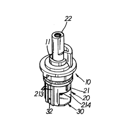
Vanne de régulation améliorée destinée à un robinet mélangeur constituée d'un support de vanne, d'un arbre de manoeuvre et d'une plaque de retenue de l'eau à deux sorties. L'arbre de manoeuvre comprend une tige et un corps de vanne à deux étages doté d'une chambre à la partie inférieure. La chambre comporte de nombreuses tiges cylindriques, incluant 4 longues et d'autres courtes qui sont placées dans un arrangement ordonné. Les tiges cylindriques sont utilisées pour diminuer le bruit associé à l'écoulement turbulent traversant le corps de la vanne, et les 4 longues tiges soutiennent la plaque de retenue de l'eau en place et empêchent un joint d'étanchéité comprimé par un ressort de tomber dans la chambre par les sorties. La tige de l'arbre de manoeuvre peut ainsi tourner avec plus d'aisance, et le bruit résultant du fonctionnement peut être réduit.


Abrégé anglais


An improved control valve for use in a mixing
valve has a valve mount, a spindle assembly and a water
restraining plate having two outlets. The spindle assembly
has a spindle rod and a two staged valve body having a
chamber at the lower portion thereof. In the chamber are
there a plurality of cylindrical posts, including 4 long
posts and other short posts that are arranged in order. The
cylindrical posts are used to reduce the noise of turbulent
flow passing through the valve body and the 4 long posts
support the water restraining plate in place and stop a
spring biased sealing pad from dropping into chamber via
the outlets. Thus, the spindle rod of the spindle assembly
can be rotated more smoothly and the noise produced in
operation can be minimized.

Revendications

Note : Les revendications sont présentées dans la langue officielle dans laquelle elles ont été soumises.


CLAIM


I claim:
1. An improved control valve for use in a dual-handled
hot/cold water mixing faucet, comprising a valve mount, a
spindle assembly and a water restraining plate wherein said
valve mount is a hollow tube having a countersunk through
hole and said spindle assembly has a two-staged spindle
body in connection to a spindle rod with a sealing ring
attached to the root of said spindle rod; a chamber is
defined in the portion of said spindle assembly having a
larger diameter and two openings disposed on the wall of
said chamber; a shoulder is disposed at the top edge of
said chamber; said spindle rod is led through the
countersunk through hole of said valve mount and partially
sticks out of the valve mount; said control valve is
characterized in that:
3 rings of cylindrical rods are housed in said chamber with
the inner and outer rings of cylindrical rods of a short
form and the intermediate ring of cylindrical rods of a
mixture of long and short forms;
a flanged wall is disposed at the top edge of said spindle
assembly with two recesses defined on the periphery thereof
and two discharge openings are disposed on the wall of the
two-staged spindle assembly at the larger portion thereof:
said water restraining plate made of stainless steel has


two tear-drop shaped outlets and two symmetric T-shaped
lugs disposed on the preiphery thereof;
said water restraining plate are secured in place to said
spindle assembly by engaging said T-shaped lugs with said
recesses on said flanged wall;
whereby said long cylindrical rods abut against said water
restraining plate so as to support the same firmly in place
and and said long and short cylindrical rods housed in said
chamber reduce operation noise due to air resonance in said
chamber and makes water flow in said chamber in a smooth
manner; said tear-drop shaped outlets of said water
restraining plate can prevent a spring biased sealing pad
which abuts against said water restraining plate from
dropping into said chamber in operation.

Description

Note : Les descriptions sont présentées dans la langue officielle dans laquelle elles ont été soumises.


21 ~2763


I~BQVE~_~Q~nL_V~ E_EQB_U~E_I~
L_~B~3aLEL~n~CQLL~EB_~ G_E~ E~

~BGBnU~n_QE_~E_l~E~l
The present invention relates to an improved
control valve for use in a mixing faucet. The control valve
has a valve mount, a spindle assemblY and a water
restraining plate having two outlets. The sPindle assembly
has a spindle rod and a two staged valve body having a
chamber at the lower portion thereof. In the chamber are
there a plurali tY of cylindrical posts, including 4 long
posts and other short posts that are arranged in order. The
cylindrical posts are used to reduce the noise of~turbulent
flow passing through the valve body and the 4 long posts
support the water restraining plate in place and stop a
spring biased sealing pad from dropping into chamber via
the outlets. Thus. the spindle rod of the sPindle assembly
can be rotated more smoothly and the noise produced in
operation can be minimized.
Referring to Fig. 1, the perspective diagram
showing the exploded components of a reversely disposed
control valve of a prior art. Such a valve has a valve
mount 10, a spindle 20 and a stoP plate ~0. The valve mount
has a countersink hole 11. The sPindle 20 has a two-
staged spindle body 21 and a sPindle rod 22 ext;ending-from
the spindle body 21 with a sealing ring 23 secured to the

21 92763


root of the spindle rod 22. A chamber 211 is defined at the
portion having a larger diameter of the two-staged spindle
body 21 . A shoulder 212 is disposed at the top edge of the
chamber 211. An outlet cut 214 is disposed on the wall of
the chamber 211 and two parallel vertical ribs 213 are
placed on each side of the outlet cut 214. The stop Plate
30 has a crescent-shaped discharge opening 31 and a locking
lug 32 positioned at each of two oPposite sides thereof so
as to secure the stop plate 3~ to the sPindle body 21 by
engaging the lugs 32 with the Paired ribs 213. Fig. lA
shows the assembly of the prior art valve in a normal
Position.
Referring further to Figs. 2A, 2a- Figs. 2D, 2d,
the detailed operation modes of the prior art of ~ig. 1 are
illustrated in a step-by-step manner. ~n operation, the
conventional control valve is placed in a cavity 2 of a
mixing faucet 1 and is locked in place by a cap 3 and a
handle 4; as shown in Fig. 5D. The stoP plate 30 abuts
against a sealing pad 4~ biased by a spring 41. The
clockwise rotation of the spindle rod 20 varies the
relative Position of the discharge opening 31 and the
sealing pad 4~ so as to gradually vary the volume of
discharged water via the opening 3~.
There are 3 drawbacks associated with su~h a prior
art control valve given as below:
1. When the valve is closed, some air will remain in the

21 92763
'_

chamber 211, and the reopening of the valve to PRrmit water
to flow in will cause the air to Produce noise as a result
of resonance.
2. The stoP plate 30 is easily deformed as a result of
impact of the discharged water, and the sealing pad 40 is
easy to droP into the opening 31 of the stop plate 30 when
it is Placed at its full-discharge position, as shown in
Fig. 2d.
3. The stoP Plate 30 engaged with the spindle body 21 by
way of the lugs 32 and the ribs is easily separated from
the spindle bodY 21.
,

~ y-QE-~E-T~yEN~lQ~

Therefore, the primary obiect of the present
invention is to Provide an imProved control valve for a
dual-handled hot/cold water mixing faucet which has 3 rings
of cylindrical Posts housed in a chamber through which
water is led so as to make the resonance noise caused by
the water flowing through the valve to be minimized and to
make water flow in a more smooth manner.
Another obiect of the present invention is to
provide an imProved control valve for a mixing faucet
wherein 4 long cylindrical Posts housed in the chamber are
used to suPport a water restraining plate in

21 92763
.

place, preventing the water restraining plate from
deformation in oPeration in one aspect and Preventing a
sealing Pad from dropping into the outlets defined on the
water restraining plate so as to make the spindle rod
rotated in a more smooth manner.
One further object of the present invention is to
provide an improved control valve wherein the water
restraining Plate is placed in a shoulder defined at the
toP edge of the chamber and is firmlY retained in place bY
two lugs engaged with two cuts on the PeripherY of the top
edge of the chamber.
. --

~IEE_aE~C~lP~lQ~_QE_~E_nB~llLlN~

Fig. 1 is a Perspective diagram showing the exploded
components of a conventional control valve of a mixing
faucet; D '
Fig. lA is a diagram showing an assembly of the
conventional faucet shown in Fig.1;
Figs. 2A, 2a, 2B, 2b. 2C.2c. 2D. 2d are paired sectional
diagrams showing the detailed operation steps of the
conventional faucet;
Fig. 3 is a perspective diagram showing the exploded
components of the present invention;
Fig. 3A is a plane view of the cylindrical posts disposed
in the chamber:

2~ 92763


Fig. 4 is a diagram showing the assembly of the present
invention;
Figs. 5A, 5a, 5B, 5b. 5C, 5c, 5D, 5d are sectional diagrams
showing the detailed operation modes of the present
nvention.

~E~ILEL~E~C~IP~In~_QE_~E_e~EEEBBELE~n~l~E~

Referring to Fig.3, the exploded comPonents of the
control valve of the present invention are; reversely
illustrated perspectively. The control valve of the present
invention is comprised of a valve mount 50, a spindle
assembly 60 and a water restraining plate 70.
The valve mount 50 is a hollow tube having a
countersunk through hole 51 which has a smaller diameter at
the upPer portion and a larger diameter at the lower
portion. The spindle assembly 60 is made up of a two-staged
valve body 61 and a spindle column 62 extending from the
va,lve body 61. A sealing ring 63 is attached to the root of
the spindle column 62.
A chamber 611 is defined at the lower portion of
the two-staged valve body 61 and a peripheral supporting
shoulder 612 is disPosed at the top edge of the valve
cha~ber 611. At the bottom of the valve chamber 611, when
reversely placed as shown in Fig. 3. There are 3 rings of
vertical cYlindrical rods disposed in the chamber 611, the

f 21 92763

outer and inner rings of the vertical rods are of short
vertical rods 613 and the intermediate ring of vertical
rods are mixture of 4 long vertical rods 614 and a
plurality of short vertical rods 613.
The top edge of the two-staged valve body 61 is
Provided with a vertical flange 615 on the periPhery
thereof with two recesses 616 defined thereon. There are
two symmetric discharge openings 617 defined on the wall of
the larger portion of the two-staged valve bodY 61. The
water restraining Plate 70 made of stainless steéi has two
tear-drop shaPed outlets 71. There are two sYmmetricallY
disPosed T-shaped lugs 72 defined on the water restraining
Plate 70 and engaged with the two corresPonding recesses
616 for fixing purpose.
Referring to Fig. 4, the PersPective diagram
showing the assembly of the present invention. As further
shown in Figs. 5A, 5a- 5D, 5d, the operation modes of the
present invention are illustrated in details. In assemblY,
the spindle rod 62 of the spindle assembly 61 is led
through the two-staged hole of the valve mount 50 with the
spindle rod 62 partially extended outwardly from the valve
mount, as shown in Fig. 4. The smaller portion of the two-
staged sPindle assemblY 60 is housed in the larger Portion
of the two staged hole 51 of the valve mount 50.
The water restraining plate~-70 is placed in the
shoulder 612 surrounded by the top vertical flange 615 and

~ 2192763


is secured in Place by engaging the two T-shaPed lugs 72
with the recesses 616 by bending the same downwardlY. The
plate 70 ;s also supPorted in place bY the 4 long
cylindrical rods 614 in the chamber 611 of the spindle
assembly 61 so as to prevent the Plate 70 from deformation
due to impact of incoming water.
In assembly, the control valve assemblY of the
present invention is housed in a receiving cavity 2 of a
mixing faucet 1 and a locking caP 3 and a handle 4 are
mounted onto the faucet 1. The water restraining plate 70
is in abutment against a sealing pad 40 biased by a spring
41. The clockwise rotation of the spindle rod 62 will vary
the relative Position of the outlets 71 of the water
restraining plate 70 and the sealing pad 40, as shown in
Figs. 5a - 5d. i.e., the oPening level of the outlets 71
as well the volume of discharged water are accordingly
varied.
There are a number of advancements associated with
the control valve of the present invention given as below:
1. The 3 rings of cylindrical rods housed in the chamber
611 of the spindle assembly 60 can reduce the vo;lume of air
left in the chamber 611 and water therein is led windingly
through the chamber 611 so as to minimize the resonance
noise in operation and make the water discharged in a more
smooth manner.
2. The water restraining plate 70 is supported in place by

21 92763


the 4 long cylindrical rods 614 and is kept well in balance
and is prevented from deformation due to impact; of water
pressure apPlied thereon and the sealing Pad 40 is
effectively stoPPed from dropping into the chamber via the
outlets 71.
3. The T-shaped lugs 72 of the water restraining plate 70
engage firmlY with the two recesses 616 of the spindle
assembly 60 so as to make the plate 70 secure safely in
place without easily disengaged from the spindle assembly
60.

Dessin représentatif
Une figure unique qui représente un dessin illustrant l'invention.
États administratifs

Pour une meilleure compréhension de l'état de la demande ou brevet qui figure sur cette page, la rubrique Mise en garde , et les descriptions de Brevet , États administratifs , Taxes périodiques et Historique des paiements devraient être consultées.

États administratifs

Titre Date
Date de délivrance prévu 1999-06-01
(22) Dépôt 1996-12-12
Requête d'examen 1996-12-12
(41) Mise à la disponibilité du public 1998-06-12
(45) Délivré 1999-06-01
Réputé périmé 2005-12-12

Historique d'abandonnement

Il n'y a pas d'historique d'abandonnement

Historique des paiements

Type de taxes Anniversaire Échéance Montant payé Date payée
Le dépôt d'une demande de brevet 0,00 $ 1996-12-12
Enregistrement de documents 0,00 $ 1997-03-13
Taxe de maintien en état - Demande - nouvelle loi 2 1998-12-14 50,00 $ 1998-09-10
Taxe finale 150,00 $ 1999-02-22
Taxe de maintien en état - brevet - nouvelle loi 3 1999-12-13 50,00 $ 1999-10-26
Taxe de maintien en état - brevet - nouvelle loi 4 2000-12-12 50,00 $ 2000-08-23
Taxe de maintien en état - brevet - nouvelle loi 5 2001-12-12 75,00 $ 2001-08-24
Taxe de maintien en état - brevet - nouvelle loi 6 2002-12-12 150,00 $ 2002-09-25
Taxe de maintien en état - brevet - nouvelle loi 7 2003-12-12 150,00 $ 2003-10-24
Titulaires au dossier

Les titulaires actuels et antérieures au dossier sont affichés en ordre alphabétique.

Titulaires actuels au dossier
CHUNG CHENG FAUCET CO., LTD.
Titulaires antérieures au dossier
KO, HSI-CHIA
Les propriétaires antérieurs qui ne figurent pas dans la liste des « Propriétaires au dossier » apparaîtront dans d'autres documents au dossier.
Documents

Pour visionner les fichiers sélectionnés, entrer le code reCAPTCHA :


Pour visualiser une image, cliquer sur un lien dans la colonne description du document. Pour télécharger l'image (les images), cliquer l'une ou plusieurs cases à cocher dans la première colonne et ensuite cliquer sur le bouton "Télécharger sélection en format PDF (archive Zip)" ou le bouton "Télécharger sélection (en un fichier PDF fusionné)".

Liste des documents de brevet publiés et non publiés sur la BDBC .

Si vous avez des difficultés à accéder au contenu, veuillez communiquer avec le Centre de services à la clientèle au 1-866-997-1936, ou envoyer un courriel au Centre de service à la clientèle de l'OPIC.


Description du
Document 
Date
(yyyy-mm-dd) 
Nombre de pages   Taille de l'image (Ko) 
Page couverture 1998-06-10 1 48
Page couverture 1997-04-17 1 15
Abrégé 1997-04-17 1 22
Description 1997-04-17 8 248
Revendications 1997-04-17 2 57
Dessins 1997-04-17 3 114
Page couverture 1999-05-26 1 48
Dessins représentatifs 1999-05-26 1 5
Dessins représentatifs 1998-06-10 1 5
Correspondance 1999-02-22 2 51
Correspondance 2001-08-24 1 35
Correspondance de la poursuite 1996-12-12 3 136