Sélection de la langue

Search

Sommaire du brevet 2194346 

Énoncé de désistement de responsabilité concernant l'information provenant de tiers

Une partie des informations de ce site Web a été fournie par des sources externes. Le gouvernement du Canada n'assume aucune responsabilité concernant la précision, l'actualité ou la fiabilité des informations fournies par les sources externes. Les utilisateurs qui désirent employer cette information devraient consulter directement la source des informations. Le contenu fourni par les sources externes n'est pas assujetti aux exigences sur les langues officielles, la protection des renseignements personnels et l'accessibilité.

Disponibilité de l'Abrégé et des Revendications

L'apparition de différences dans le texte et l'image des Revendications et de l'Abrégé dépend du moment auquel le document est publié. Les textes des Revendications et de l'Abrégé sont affichés :

  • lorsque la demande peut être examinée par le public;
  • lorsque le brevet est émis (délivrance).
(12) Brevet: (11) CA 2194346
(54) Titre français: ACCESSOIRE DE TUYAUTERIE SANITAIRE A EAU
(54) Titre anglais: SANITARY WATER FITTING
Statut: Réputé périmé
Données bibliographiques
(51) Classification internationale des brevets (CIB):
  • F16K 11/074 (2006.01)
  • E03C 1/04 (2006.01)
  • F16K 27/04 (2006.01)
(72) Inventeurs :
  • BECKER, ALBERT (Allemagne)
(73) Titulaires :
  • AMERICAN STANDARD INC. (Etats-Unis d'Amérique)
(71) Demandeurs :
  • AMERICAN STANDARD INC. (Etats-Unis d'Amérique)
(74) Agent: RIDOUT & MAYBEE LLP
(74) Co-agent:
(45) Délivré: 2000-06-27
(22) Date de dépôt: 1997-01-03
(41) Mise à la disponibilité du public: 1997-07-10
Requête d'examen: 1997-01-03
Licence disponible: S.O.
(25) Langue des documents déposés: Anglais

Traité de coopération en matière de brevets (PCT): Non

(30) Données de priorité de la demande:
Numéro de la demande Pays / territoire Date
19600646.5 Allemagne 1996-01-10

Abrégés

Abrégé français

Accessoire de tuyauterie sanitaire à eau muni d'une couronne d'appui disposée comme palier de glissement entre le corps de l'accessoire de tuyauterie et le manchon d'appui. La couronne d'appui obture une rainure circulaire qui maintient des bagues d'étanchéité du manchon d'appui au moyen d'un joint externe situé au niveau de la couronne d'appui. Dans son déploiement axial, elle entoure une ouverture de conduite d'eau qui se situe entre une conduite d'eau en circulation et un élément de raccordement pivotant à bec. Cette invention offre comme avantage que le courant d'eau de la conduite d'eau en circulation allant vers l'élément de raccordement pivotant à bec soit dirigé de telle façon que la formation de dépôts calcaires dans le secteur des bagues d'étanchéité s'en trouve considérablement limitée, sinon même entièrement éliminée, même après une longue durée d'utilisation. Étant donné que l'eau n'est plus en mesure de s'insinuer entre les éléments qui bougent les uns par rapport aux autres et que la couronne d'appui elle-même contribue à protéger les bagues d'étanchéité, il n'y a plus guère de possibilité que d'importantes quantités de dépôts calcaires se produisent dans ce secteur sensible.


Abrégé anglais


A sanitary water fitting having a bearing ring arranged as a sliding
bearing between the fitting body and the bearing sleeve. The bearing ring seals off
a circling groove holding sealing rings from the bearing sleeve and is itself sealed
off from the bearing sleeve by means of an external seal placed at the bearing ring.
In its axial extension it borders a water passage opening which is between a
circulating water channel and a swivel spout connection piece. The advantage of
this invention is that the water flow in the circulating water channel and towards the
swivel spout connection piece is controlled in such a way that the formation of lime
deposits in the area of the sealing rings is considerably limited even after a
relatively long period of operation, or even prevented completely. Since the water
can no longer get in between the parts moving in relation to each other and the
bearing ring itself helps to protect the sealing rings, there is no longer a possibility of
serious levels of lime deposits settling in this sensitive area.

Revendications

Note : Les revendications sont présentées dans la langue officielle dans laquelle elles ont été soumises.


-6-
CLAIMS:
1. A sanitary fitting comprising:
a stationary fitting body;
a bearing sleeve which surrounds said fitting body and is pivoted
thereon by at least one bearing ring, said bearing ring and said fitting body
form a circulating water channel;
a swivel spout connection piece having one end which extends into
said bearing sleeve;
inlet and outlet channels;
a valve control unit mounted on said fitting body and connected to said
inlet and outlet channels and to said circulating water channel via said
outlet
channel, said circulating water channel leading to an arm of said swivel
spout;
circling collars bordering said circulating water channel, said circling
collars form part of a circling groove which contains sealing rings;
said bearing ring seals off said circling groove from said bearing
sleeve, said bearing ring bordering a water passage hole located between
said circulating water channel and said swivel spout connection piece.
2. A sanitary fitting in accordance with claim 1 wherein said bearing ring
consists of an upper and a lower part ring, each arranged symmetrically in
relation to said circulating water channel.
3. A sanitary fitting in accordance with claim 2 wherein a separate upper
and lower bearing ring is provided.
4. A sanitary fitting in accordance with claim 1 wherein said bearing ring
which borders said passage opening includes a bevelled edge which borders
said circulating water channel outwards towards said swivel spout
connection piece.

Description

Note : Les descriptions sont présentées dans la langue officielle dans laquelle elles ont été soumises.


w - CA 02194346 1999-07-OS
-1 -
SANITARY WATER FITTING
BACKGROUND OF INVENTION
The present invention is directed to a sanitary water fitting having a
swivel support connection piece of which one end extends into a bearing
sleeve which encases a stationary fitting body. The bearing sleeve is
pivoted on the fitting body by means of at least one bearing ring and which
together with the fitting body forms a circulating water channel, which is
closed off by means of sealing rings. A valve control or regulating unit is
mounted on top of the fitting body which is connected to water inlet channels
in the fitting body and is also connected to the circulating water channel via
a
water outlet channel. The circulating water channel leading to the arm of the
swivel outlet connection piece is bordered by circling collars whose surfaces
form part of the wall of a circling groove holding the sealing rings.
In known sanitary water fittings, such as that disclosed in U.S. Patent
No. 5,301,715, an upper and a lower bearing ring is provided for pivoting the
swing spout connection piece on the fitting body in its external overlapping
areas. These bearing rings are preferably made of sliding, long-wearing
plastic. In the central area between the bearing rings, the swivel spout
connection piece is seated, in direct contact with the sealing rings.
One disadvantage of such a construction is that, depending on the
respective water quality and in particular the water hardness levels of the
area, lime deposits can form in the waterways inside the fitting after a short
period of operation. This makes it increasingly difficult for the swivel spout
connection piece to move in relation to the fitting body, especially in the
area
of the sealing rings. . . . . . . . . . . . . . . . . . . . . . . . . . . . .
. . . . . . . . . . . . . . . .


X194346
2 -
Furthermore, if the necessary force is used to turn the swing spout connection
piece, damage can occur to the sealing rings resulting in leaks from the
waterways.
SUMMARY OF THE INVENTION
It is therefore an object of the invention to eliminate the aforesaid
disadvantage and provide a sanitary water fitting of simple construction and
reliable
function.
These and other objects are achieved by the present invention which
provides a sanitary water fitting having a bearing ring arranged as a sliding
bearing
between the fitting body and the bearing sleeve. The bearing ring seals off a
circling groove holding sealing rings from the bearing sleeve and is itself
sealed off
from the bearing sleeve by means of an external seal placed at the bearing
ring. In
its axial extension it borders a water passage opening which is between a
circulating
water channel and a swivel spout connection piece. The advantage of this
invention
is that the water flow in the circulating water channel and towards the swivel
spout
connection piece is controlled in such a way that the formation of lime
deposits in
the area of the sealing rings is considerably limited even after a relatively
long
period of operation, or even prevented completely. Since the water can no
longer
get in between the parts moving in relation to each other and the bearing ring
itself
helps to protect the sealing rings, there is no longer a possibility of
serious levels of
lime deposits settling in this sensitive area.
In accordance with an embodiment of the invention, a swivel spout
connection piece is held to the fitting body by means of two partial rings
which are
each formed in the same way and arranged symmetrically in relation to the
circulating water channel. These partial rings can either be connected
together to


~i94346
- 3 -
form a one-piece ring element or two bearing rings can be provided which can
also
be arranged separately from one another and inserted during assembly.
The bearing ring edge which borders the passage opening can on its
surface bordering the circulating water channel be bevelled into the passage
opening and outwards towards the swivel spout connection piece. The formation
of
the appropriate edge serves to regulate the water flow as desired without the
water
streaming onto the sealing rings in the turbulent area.
BRIEF DESCRIPTION OF THE DRAWINGS
The invention will be more fully appreciated from the following detailed
description when the same is considered in connection with the accompanying
drawings in which:
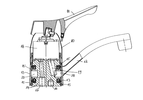
Fig. 1 is a sectional side view of a sanitary water fitting in accordance
with the claimed invention; and
fig. 2 is an enlarged sectional representation of the fitting in Fig. 1
showing the water channels.
DETAILED DESCRIPTION OF THE INVENTION
Reference is now made to Figure 1 which shows a sanitary water
fitting having a fitting casing 10 on which a swivel lever 11 is mounted for
regulating
quantity and temperature. The fitting has a swivel spout connection piece 12
which
is located on a bearing sleeve 13, which is pivoted on a stationary fitting
body 14,
whereby the bearing sleeve 13 is pivoted on the fitting casing 10 and the
fitting body
14 by means of bearing rings 15, described below in detail.


CA 02194346 1999-07-OS
-4-
The fitting body 14 and thus the sanitary water fitting is mounted by
means of a stud bolt 16 to a sink (not shown). The water inlet 17 enters from
underneath the fitting body 14 and leads to a water control or regulating unit
which, in a preferred embodiment as shown in the drawings, comprises a
cartridge 18 placed in the fitting casing 10. The swivel lever 11 is connected
to cartridge 18 to regulate the water quantity and temperature.
From cartridge 18 a water outlet channel 19 leads to a circulating
water channel 20 formed in the fitting body 14. The circulating water
channel is connected to the swivel spout connection piece 12 in the sanitary
water fitting by means of a hole 28 so that the mixed water coming from
cartridge 18 can flow out swivel spout connection piece 12. The circulating
water channel 20 is bordered in the fitting body 14 by circling collars 21,
whose surfaces which are not facing each other simultaneously form part of
the wall for a circling groove 29 in which sealing rings 22 are fitted, which
seal off the circulating water channel 20.
Befinreen the fitting body 14 and the bearing sleeve 13 there are
bearing rings 15, one upper and one lower ring, to enable the swivel spout
connection piece 12 to be pivoted on the fitting body 14. Each bearing ring
15 seals off the circling groove 29 and the sealing ring 22 located in groove
29. Each bearing ring 15 is itself sealed off from the bearing sleeve 13 by
means of a seal 27 placed in a circling groove 26. The two bearing rings 15
form a boundary by their axial extensions with end edges 24 for the water
passage hole 28 between the circulating water channel 20 and the swivel
spout connection piece 12. In order to regulate favorable flow conditions the
corresponding surfaces of both bearing rings 15 are bevelled 25 into the
water passage hole 28 and outwards towards the swivel spout connection
piece 12. As a result, the water flowing through passage hole 28 is kept
away or diverted from the remaining contact surface with sealing ring 22
befinreen .....................................................


~3~4346
- 5 -
circling collar 21 and bearing ring 15. Since there is a seal both between
fitting
body 14 and bearing ring 15 and between the bearing ring 15 and the bearing
sleeve 13, the water cannot get in between the components which turn in
relation to
each other so that lime deposits, which would cause difficulties, cannot
settle.
Although illustrative embodiments of the present invention have been
described herein with reference to the accompanying drawings, it is to be
understood that the invention is not limited to these precise embodiments, and
that
various other changes and modifications may be effected herein by one skilled
in
the art without departing from the scope or spirit of the invention.

Dessin représentatif
Une figure unique qui représente un dessin illustrant l'invention.
États administratifs

Pour une meilleure compréhension de l'état de la demande ou brevet qui figure sur cette page, la rubrique Mise en garde , et les descriptions de Brevet , États administratifs , Taxes périodiques et Historique des paiements devraient être consultées.

États administratifs

Titre Date
Date de délivrance prévu 2000-06-27
(22) Dépôt 1997-01-03
Requête d'examen 1997-01-03
(41) Mise à la disponibilité du public 1997-07-10
(45) Délivré 2000-06-27
Réputé périmé 2005-01-04

Historique d'abandonnement

Il n'y a pas d'historique d'abandonnement

Historique des paiements

Type de taxes Anniversaire Échéance Montant payé Date payée
Requête d'examen 400,00 $ 1997-01-03
Le dépôt d'une demande de brevet 0,00 $ 1997-01-03
Enregistrement de documents 0,00 $ 1997-03-20
Taxe de maintien en état - Demande - nouvelle loi 2 1999-01-04 100,00 $ 1999-01-04
Taxe de maintien en état - Demande - nouvelle loi 3 2000-01-03 100,00 $ 1999-12-21
Taxe finale 300,00 $ 2000-03-23
Taxe de maintien en état - brevet - nouvelle loi 4 2001-01-03 100,00 $ 2000-12-20
Taxe de maintien en état - brevet - nouvelle loi 5 2002-01-03 150,00 $ 2001-12-20
Taxe de maintien en état - brevet - nouvelle loi 6 2003-01-03 150,00 $ 2002-12-19
Titulaires au dossier

Les titulaires actuels et antérieures au dossier sont affichés en ordre alphabétique.

Titulaires actuels au dossier
AMERICAN STANDARD INC.
Titulaires antérieures au dossier
BECKER, ALBERT
IDEAL STANDARD GMBH
Les propriétaires antérieurs qui ne figurent pas dans la liste des « Propriétaires au dossier » apparaîtront dans d'autres documents au dossier.
Documents

Pour visionner les fichiers sélectionnés, entrer le code reCAPTCHA :


Pour visualiser une image, cliquer sur un lien dans la colonne description du document. Pour télécharger l'image (les images), cliquer l'une ou plusieurs cases à cocher dans la première colonne et ensuite cliquer sur le bouton "Télécharger sélection en format PDF (archive Zip)" ou le bouton "Télécharger sélection (en un fichier PDF fusionné)".

Liste des documents de brevet publiés et non publiés sur la BDBC .

Si vous avez des difficultés à accéder au contenu, veuillez communiquer avec le Centre de services à la clientèle au 1-866-997-1936, ou envoyer un courriel au Centre de service à la clientèle de l'OPIC.


Description du
Document 
Date
(yyyy-mm-dd) 
Nombre de pages   Taille de l'image (Ko) 
Dessins 1997-04-28 2 46
Page couverture 1998-08-20 1 16
Dessins représentatifs 1998-03-30 1 22
Dessins représentatifs 2000-05-30 1 13
Description 1997-04-28 5 178
Abrégé 1997-04-28 1 25
Page couverture 1997-04-28 1 16
Revendications 1997-04-28 2 40
Revendications 1999-07-05 1 37
Description 1999-07-05 5 186
Page couverture 2000-05-30 2 74
Cession 1997-01-03 13 336
Taxes 1999-12-21 1 30
Cession 2006-01-26 9 234
Correspondance 2000-03-23 1 41
Poursuite-Amendment 1999-01-05 2 3
Poursuite-Amendment 1999-07-05 6 221
Taxes 1999-01-04 1 35