Sélection de la langue

Search

Sommaire du brevet 2195052 

Énoncé de désistement de responsabilité concernant l'information provenant de tiers

Une partie des informations de ce site Web a été fournie par des sources externes. Le gouvernement du Canada n'assume aucune responsabilité concernant la précision, l'actualité ou la fiabilité des informations fournies par les sources externes. Les utilisateurs qui désirent employer cette information devraient consulter directement la source des informations. Le contenu fourni par les sources externes n'est pas assujetti aux exigences sur les langues officielles, la protection des renseignements personnels et l'accessibilité.

Disponibilité de l'Abrégé et des Revendications

L'apparition de différences dans le texte et l'image des Revendications et de l'Abrégé dépend du moment auquel le document est publié. Les textes des Revendications et de l'Abrégé sont affichés :

  • lorsque la demande peut être examinée par le public;
  • lorsque le brevet est émis (délivrance).
(12) Demande de brevet: (11) CA 2195052
(54) Titre français: APPAREIL PULVERISATEUR POUR CUVETTE DE W.C.
(54) Titre anglais: SPRAYING APPARATUS FOR USE WITH A FLUSH TOILET
Statut: Réputée abandonnée et au-delà du délai pour le rétablissement - en attente de la réponse à l’avis de communication rejetée
Données bibliographiques
Abrégés

Abrégé français

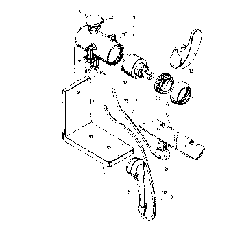
La présente invention se rapporte à un appareil pulvérisateur comportant un pulvérisateur mobile, un gicleur fixe et un corps principal. Le pulvérisateur mobile comporte un tuyau flexible et une tête de pulvérisation raccordée à l'une de ses extrémités. Le gicleur fixe comporte un tuyau à eau et un gicleur raccordé à l'une de ses extrémités. Le gicleur est conçu pour positionnement derrière le rebord d'une cuvette de W.C.. Le corps principal est formé d'une chambre d'eau destinée au raccordement à la source d'alimentation; un premier orifice de sortie est destiné à être raccordé au tuyau flexible et un deuxième orifice de sortie est destiné à être raccordé au tuyau d'eau; un régulateur de débit est monté en interposition entre la chambre d'eau et les premier et deuxième orifices de sortie d'eau. Le régulateur de débit est pourvu d'un robinet qui permet de diriger le débit d'eau vers l'un ou l'autre orifices de sortie. L'eau giclant du pulvérisateur peut être utilisée à des fins d'hygiène personnelle par la personne assise sur le siège de la cuvette.


Abrégé anglais


A spraying apparatus includes a movable spraying
unit, a stationary spraying unit and a main body. The
movable spraying unit includes a flexible tube and a
spraying head on one end of the flexible tube. The
stationary spraying unit includes a water tube and a
spraying nozzle on one end of the water tube. The
spraying nozzle is adapted to be positioned at a rear
part of the rim portion of the toilet bowl. The main
body has a water chamber adapted to be communicated
fluidly with a water source, a first water outlet
connected to the flexible tube, a second water outlet
connected to the water tube, and a flow control valve
unit for communicating fluidly the water chamber and
the first and second water outlets. The flow control
valve unit is operable so as to direct water flowing
into the water chamber to a selected one of the first
and second water outlets. Water flowing through the
spraying nozzle can be used to wash a person seated on
the toilet bowl.

Revendications

Note : Les revendications sont présentées dans la langue officielle dans laquelle elles ont été soumises.


I CLAIM:
1. A spraying apparatus for use with a flush toilet
which has a toilet bowl with a rim portion and a seat
on the rim portion, said spraying apparatus comprising:
a movable spraying unit including a flexible tube
and a spraying head on one end of said flexible tube;
a stationary spraying unit including a water tube
and a spraying nozzle on one end of said water tube,
said spraying nozzle being adapted to be positioned at
a rear part of the rim portion of the toilet bowl; and
a main body having a water chamber adapted to be
communicated fluidly with a water source, a first water
outlet connected to said flexible tube, a second water
outlet connected to said water tube, and a flow control
valve unit for communicating fluidly said water chamber
and said first and second water outlets, said flow
control valve unit being operable so as to direct water
flowing into said water chamber to a selected one of
said first and second water outlets;
whereby, water flowing through said spraying nozzle
can be used to wash a person seated on the toilet bowl.
2. The spraying apparatus according to Claim 1, wherein
said main body further has a first water inlet adapted
to be connected to a hot water source, a second water
inlet adapted to be connected to a cold water source,
and a mixing control valve unit for communicating
fluidly said first and second water inlets and said

water chamber, said mixing control valve unit being
operable so as to mix hot water from said first water
inlet with cold water from said second water inlet and
to control flow of the mixed water into said water
chamber.
3. The spraying apparatus according to Claim 1, wherein
said stationary spraying unit further includes a
positioning plate having said spraying nozzle mounted
thereon, said positioning plate being adapted to be
clamped between the seat and the rim portion of the
toilet bowl.
4. The spraying apparatus according to Claim 1, further
comprising a mounting unit adapted to mount said main
body on a wall adjacent to the toilet bowl.

Description

Note : Les descriptions sont présentées dans la langue officielle dans laquelle elles ont été soumises.


2 1 95~52
SPRAYING APPARATUS FOR USE WITH A FLUSH TOILET
BACKGROUND OF THE lNv~N-LlON
1. Field of the Invention
The present invention relates to a spraying
apparatus for use with a flush toilet, more
particularly to a spraying apparatus which can be
mounted directly on a conventional flush toilet to
permit washing of a person seated on the latter.
2. Description of the Related Art
A conventional spraying apparatus for use with a
flush toilet includes a stationary spraying nozzle that
is secured below the toilet seat at a rear part of the
rim portion of the toilet bowl. Since the conventional
spraying apparatus is integral to the toilet seat, it
cannot be mounted directly on a flush toilet. As such,
the original toilet seat and cover must be entirely
replaced when a spraying apparatus is to be equipped on
the flush toilet. Moreover, the stationary spaying
no~zle of the conventional spraying apparatus is not
quite convenient for different users and cannot be used
to wash different body parts effectively and thoroughly
as necessary.
SUMMARY OF THE lNV~NllON
The main object of the present invention is to
provide a simple and more economical spraying apparatus
which can be directly and easily mounted on a
conventional flush toilet.

2 ~ 95052
Accordingly, the spraying apparatus of the present
invention includes a movable spraying unit, a
stationary spraying unit and a main body. The movable
spraying unit includes a flexible tube and a spraying
head on one end of the flexible tube. The stationary
spraying unit includes a water tube and a spraying
nozzle on one end of the water tube. The spraying
nozzle is adapted to be positioned at a rear part of
the rim portion of the toilet bowl. The main body has a
water chamber adapted to be communicated fluidly with a
water source, a first water outlet connected to the
flexible tube, a second water outlet connected to the
water tube, and a flow control valve unit for
communicating fluidly the water chamber and the first
and second water outlets. The flow control valve unit
is operable so as to direct water flowing into the
water chamber to a selected one of the first and second
water outlets. Water flowing through the spraying
nozzle can be used to wash a person seated on the
toilet bowl.
BRIEF DESCRIPTION OF THE DRAWINGS
Other features and advantages of the present
invention will become apparent in the following
detailed description of the preferred embodiment with
reference to the accompanying drawings, of which:
Figure 1 is an exploded perspective view
illustrating a spraying apparatus according to a

2 1 95052
preferred embodiment of the present invention;
Figure 2 is a top, cross-sectional view illustrating
a main body of the spraying apparatus of the preferred
em~odiment;
Figure 3 is a side, cross-sectional view
illustrating the main body of the spraying apparatus of
the preferred embodiment; and
Figure 4 is a perspective view illustrating the
spraying apparatus when installed on a flush toilet.
DETAILED DESCRIPTION OF THE PREFERRED EMBODIMENT
Before the present invention is described in greater
detail, it should be noted that the ratio of the sizes
of the elements shown in the figures are merely for
illustrative purposes rather than the actual size
ratios therefor.
Referring to Figure 1, the spraying apparatus
according to a preferred embodiment of the present
invention includes a movable spraying unit 3, a
stationary spraying unit 2, a main body 1, a mounting
unit 4 and a positioning plate 5.
The movable spraying unit 3 includes a flexible tube
32 and a spraying head 31 on one end of the flexible
tube 32.
The stationary spraying unit 2 includes a water tube
22 and a spraying nozzle 21 on one end of the water
tube 22. In this embodiment, the spraying nozzle 21 is
mounted on the intermediate portion of a front edge of

2 1 95352
the positioning plate 5.
The main body 1 is supported on the mounting unit 4
and has a water chamber (not shown), a first water
inlet 112 adapted to be connected to a hot water
source, a second water inlet 113 adapted to be
connected to a cold water source, a first water outlet
111 connected to the flexible tube 32 of the movable
spraying unit 3, and a second water outlet 142
connected to the water tube 22 of the stationary
spraying unit 2. The main body 1 further has a mixing
control valve unit 12 which is retained in one end of
the main body 1 by means of a first fastening member 15
and a second fastening member 16. The mixing control
valve unit 12 is operated by a single operating handle
13.
Referring to Figures 2 and 3, the mixing control
valve unit 12 is conventional in construction and has a
first inlet port 121 which communicates fluidly the
first water inlet 112 and the water chamber, and a
second inlet port 122 which communicates fluidly the
second water inlet 113 and the water chamber. The
operating handle 13 is operable so as to mix hot water
from the first water inlet 112 with cold water from the
second water inlet 113 and to control flow of the mixed
water into the water chamber in a known manner. The
mixing control valve unit 12 further has a first outlet
port 123 which serves as a part of the water chamber.

2 1 95052
The flow control valve unit 14 is also conventional
in construction and has an inlet port 144 communicated
fluidly with the first outlet port 123 so as to serve
as another part of the water chamber, and an outlet
port 143 communicated fluidly with the first and second
water outlets 111, 142. The flow control valve unit 14
has an operating cap 141 which is operable so as to
direct water flowing into the inlet port 144 to a
selected one of the first and second water outlets 111,
142 in a known manner.
Referring to Figure 4, the spraying apparatus is
used with a flush toilet 7 which has a toilet bowl 73
with a rim portion 732 and a seat 71 on the rim portion
732. When the spraying apparatus of this embodiment is
mounted on the flush toilet, the mounting unit 4 with
the main body 1 supported thereon is first fixed on a
desired position, for example, on a wall adjacent to
the toilet bowl 73. The positioning plate 5 with the
spraying nozzle 21 mounted thereon is clamped between
the seat 71 and the rim portion 732 of the toilet bowl
73. The first and second water inlets 112, 113 are
respectively connected to the hot and cold water pipes
below a washbasin 6.
To use the spraying apparatus, the operating handle
13 of the mixing control valve unit 12 is operated so
that suitable amounts of hot and cold water are guided
through the first and second inlet ports 121, 122 and

21 950~2
into the mixing control valve unit 12. Mixed water with
a desired temperature subsequently flows out of the
mixing control valve unit 12 through the water outlet
port 123 and into the flow control valve unit 14, which
controls the flow of water either into the movable
spraying unit 3 for spraying at the spraying head 31,
or into the stationary spraying unit 2 for spraying at
the spraying nozzle 21 that is positioned at a rear
part of the rim portion 72 of the toilet bowl 73,
thereby permitting washing of the anus of a person
seated on the toilet bowl 73.
Accordingly, the spraying apparatus of the present
invention can be easily assembled onto a conventional
toilet. It is further noted that the movable spraying
unit 2 of the spraying apparatus according to the
present invention facilitates thorough washing of any
body part. The object of this invention is thus met.
With this invention thus explained, it is apparent
that numerous modifications and variations can be made
without departing from the scope and spirit of this
invention. It is therefore intended that this invention
be limited only as indicated in the appended claims.

Dessin représentatif
Une figure unique qui représente un dessin illustrant l'invention.
États administratifs

2024-08-01 : Dans le cadre de la transition vers les Brevets de nouvelle génération (BNG), la base de données sur les brevets canadiens (BDBC) contient désormais un Historique d'événement plus détaillé, qui reproduit le Journal des événements de notre nouvelle solution interne.

Veuillez noter que les événements débutant par « Inactive : » se réfèrent à des événements qui ne sont plus utilisés dans notre nouvelle solution interne.

Pour une meilleure compréhension de l'état de la demande ou brevet qui figure sur cette page, la rubrique Mise en garde , et les descriptions de Brevet , Historique d'événement , Taxes périodiques et Historique des paiements devraient être consultées.

Historique d'événement

Description Date
Inactive : CIB de MCD 2006-03-12
Demande non rétablie avant l'échéance 2000-01-14
Le délai pour l'annulation est expiré 2000-01-14
Inactive : Page couverture publiée 1999-10-01
Réputée abandonnée - omission de répondre à un avis sur les taxes pour le maintien en état 1999-01-14
Demande publiée (accessible au public) 1998-07-14
Inactive : Renseign. sur l'état - Complets dès date d'ent. journ. 1998-05-05
Inactive : Dem. traitée sur TS dès date d'ent. journal 1998-05-05
Toutes les exigences pour l'examen - jugée conforme 1997-01-14
Exigences pour une requête d'examen - jugée conforme 1997-01-14

Historique d'abandonnement

Date d'abandonnement Raison Date de rétablissement
1999-01-14

Historique des taxes

Type de taxes Anniversaire Échéance Date payée
Requête d'examen - petite 1997-01-14
Titulaires au dossier

Les titulaires actuels et antérieures au dossier sont affichés en ordre alphabétique.

Titulaires actuels au dossier
FU-HSIN TUAN
Titulaires antérieures au dossier
S.O.
Les propriétaires antérieurs qui ne figurent pas dans la liste des « Propriétaires au dossier » apparaîtront dans d'autres documents au dossier.
Documents

Pour visionner les fichiers sélectionnés, entrer le code reCAPTCHA :


Pour visualiser une image, cliquer sur un lien dans la colonne description du document. Pour télécharger l'image (les images), cliquer l'une ou plusieurs cases à cocher dans la première colonne et ensuite cliquer sur le bouton "Télécharger sélection en format PDF (archive Zip)" ou le bouton "Télécharger sélection (en un fichier PDF fusionné)".

Liste des documents de brevet publiés et non publiés sur la BDBC .

Si vous avez des difficultés à accéder au contenu, veuillez communiquer avec le Centre de services à la clientèle au 1-866-997-1936, ou envoyer un courriel au Centre de service à la clientèle de l'OPIC.


Description du
Document 
Date
(aaaa-mm-jj) 
Nombre de pages   Taille de l'image (Ko) 
Dessin représentatif 1998-07-19 1 16
Description 1997-04-30 6 196
Revendications 1997-04-30 2 53
Abrégé 1997-04-30 1 26
Dessins 1997-04-30 3 98
Rappel de taxe de maintien due 1998-09-14 1 115
Courtoisie - Lettre d'abandon (taxe de maintien en état) 1999-02-10 1 184
Correspondance reliée au PCT 1997-01-13 1 36