Note : Les descriptions sont présentées dans la langue officielle dans laquelle elles ont été soumises.
0 2 ~ ~ % 8 ~ 9
MAG~ TIC F~T.h'MR~T
BACKGROUND OF THE INVENTION
1. Field of the Invention
The present invention relates to a magnetic element
which exhibits a rapid change in magnetization with a change in
an externally applied magnetic filed.
2. Description of the Related Art
There are many devices which utilize the magnetization
behavior of a magnetic material. In addition to devices which
exhibit a continuous response to a change in an external
magnetic field such as a magnetic induction type magnetic head,
magnetic materials which exhibit a rapid magnetic reversal and
a discontinuous response when the intensity of the applied
magnetic field exceeds a predetermined value have recently been
employed. When a pickup coil is disposed in the vicinity of
such a magnetic material, a steep voltage pulse can be produced
in the coil upon a discontinuous magnetic reversal of the
magnetic material. The use of such a magnetic element can
provide a simplified apparatus which is widely applicable to
the measurement of magnetic fields such as the earth's magnetic
field, rotational speed, flow rate, etc.
Furthermore, in recent years, electronic article
surveillance systems or identification systems for preventing
the theft of merchandises or for rapidly processing the flow of
materials have become more widely used. These devices employ
identifying markers such as a transmitting circuit, an LC
~ a ~ ~ 8 ~ g
-
resonance circuit, a magnetostrictive vibrating material and a
high magnetic permeability material, as well as the above-
described magnetic material which exhibits a discontinuous
magnetic reversal. For example, U.S. Patents 4,660,025,
4,686,516 and 4,797,658 disclose a system employing a marker
made of a fine amorphous Fe based alloy wire. The
magnetization of the foregoing fine metal wire material is
extremely stable in the longitudinal direction and thus
exhibits a very sudden 180~ magnetic reversal when the magnetic
field reaches a predetermined magnitude. These characteristic
is often called a large Barkhausen discontinuity. When the
intensity of an alternating magnetic field which has been
transmitted as an inquiry signal in a monitor zone reaches a
critical value, the fine metal wire exhibits a discontinuous
magnetic reversal, thereby causing a detection coil to produce
a steep pulse voltage. The waveform of the pulse voltage thus
produced is then subjected to a frequency analysis in which the
intensity and proportion of high harmonics are determined to
identify the marker or to judge if it is necessary to sound an
alarm. This system is advantageous in that the marker is
inexpensive and provides an identifying capacity higher than
that of other systems.
Magnetic materials have been found which exhibit a
discontinuous magnetization response besides the foregoing fine
amorphous metal wire. For example, U.S. Patents 4,980,670 and
5,313,192 disclose a material obtained by annealing a slender
amorphous metal ribbon in a magnetic field. Furthermore, U.S.
Patent 5,181,020 discloses a thin film having a strong uniaxial
magnetic anisotropy formed on a polymer substrate such as a
plastic film which exhibits a discontinuous magnetic reversal.
This material exhibits excellent rectangular hysteresis
characteristics similar to the fine metal wire.
In order to practically use a thin film having a strong
uniaxial magnetic anisotropy formed on a plastic polymer
substrate as a magnetic element (e.g., as a sensor and marker),
the thin film must be cut into a desired shape together with
the substrate. However, when the laminate is mechanically cut
by a cutter, scissors or the like, unnecessary stress is
applied to the thin film even if a relatively sharp blade is
used. This stress occasionally disturbs the uniaxial magnetic
anisotropy of the thin film. Accordingly, the resulting
magnetic element is disadvantageous in that its magnetic
characteristics can vary widely.
SUMMARY OF THE INVENTION
It is therefore an object of the present invention to
provide a magnetic element having good magnetic characteristics
and little variation in magnetic characteristics even when it
is mechanically cut by a cutter, scissors or the like.
The present invention solves the foregoing problem of
the conventional art. That is, in a first embodiment, the
present invention achieves the above objections by providing a
8 n n
8u 7
magnetic element comprising a polymer substrate and a thin film
having a uniaxial magnetic anisotropy which is partly disposed
on the substrate, wherein the magnetic element exhibits a
discontinuous magnetic reversal under an applied magnetic field
5having a magnitude that is not smaller than a predetermined
value.
In the second embodiment, the present invention
provides a magnetic element comprising a polymer substrate
having thereon a coating which is coated on the substrate in a
1~frame-shaped pattern and a thin film having a uniaxial magnetic
anisotropy disposed on said coated substrate, wherein the
magnetic element exhibits a_discontinuous magnetic reversal
under an applied magnetic field having a magnitude that is not
smaller than a predetermined value.
15Despite its simple structure, the magnetic element of
the present invention exhibits excellent magnetic
characteristics. Further, the magnetic element of the present
invention exhibits little variation in magnetic characteristics
and its magnetic characteristics are therefore highly
20reproducible. Accordingly, the magnetic element of the present
invention is of a great industrial significance.
BRIEF DESCRIPTION OF THE DRAWING
In the accompanying drawings:
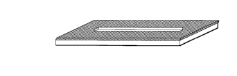
25Fig. 1 is a diagram illustrating a print pattern of a
water-soluble ink applied to the substrate in Example 1;
-- 4
Fig. 2 is a schematic diagram of the magnetic element
of the present invention prepared in Example 1;
Figs. 3 and 4 each shows a B-H loop of the magnetic
element prepared in Example 1;
5Fig. 5 is a schematic diagram illustrating the magnetic
element prepared in Comparative Example 1;
Figs. 6 and 7 each shows a B-H loop of the magnetic
element prepared in Comparative Example 1;
Figs. 8 and 9 each shows a B-H loop of the magnetic
10element prepared in Example 2; and
Fig. 10 shows a B-H loop of the magnetic element of
Example 2 where a greater magnetic field is applied to the
magnetic element.
15Description of reference numerals
1 ... Magnetic element
2 ... Thin film
3 ... Polymer substrate
20DETAILED DESCRIPTION OF THE INVENTION
The present invention is described in greater detail
below and in reference to the accompanying drawings.
The magnetic element of the present invention comprises
a thin film having a uniaxial magnetic anisotropy which is
25partly accumulated on a polymer substrate.
1 8 80 ~
As discussed above, in order to use a thin film formed
on a polymer substrate as a magnetic element, the thin film
must be cut into a desired shape together with the substrate.
This operation imparts a cutting stress to the magnetic
element.
The magnetic element of the present invention comprises
a portion which does not have the thin film disposed thereon,
that is, a so-called cutting margin. Namely, the thin film is
absent from a part of the underlying substrate. In this
arrangement, the thin film is not affected by excess cutting
stress. Thus, the discontinuous magnetization characteristics,
particularly large Barkhausen characteristics, of the magnetic
element can be stabilized. This provides a remarkable
improvement in uniformity of the magnetic characteristics.
The magnetic element of the present invention is
preferably configured such that the thin film is not present
within a range of 0.5 mm or more from an edge of the substrate.
That is, this range serves as a cutting margin on which the
thin film is not present, to thereby improve the magnetic
characteristics of the magnetic element.
Furthermore, as described above, in the magnetic
element of the present invention, the thin film disposed on the
substrate has a uniaxial magnetic anisotropy. If the thin film
does not have a uniaxial magnetic anisotropy, the resulting
magnetic element undergoes a continuous magnetic reversal.
Such a magnetic element does not exhibit a discontinuous
0 2~8 809
_
magnetic reversal even under an applied magnetic field having
a magnitude exceeding a predetermined value.
Specific examples of the alloy composition of thin film
of the magnetic element of the present invention include
crystalline materials such as NiFe, FeAlSi, FeAl and FeSi,
material having extremely fine crystalline grains of Fe or Co
alloys including at least one of B, C, N, O, etc., and
amorphous materials such as alloys of Fe, Co or Ni including at
least one of P, B, C, Zr, Nb, Si, Ti, Ta and Hf.
The thickness of the magnetic thin film is in the range
of 0.1 to 10 ~m, preferably 0.2 to 5 ~m in the present
invention. If the thickness_is_less than 0.1 ~m, the signal
intensity emitted from the magnetic thin film when the
magnetization is changed is so small. On the other hand, if
the thickness is more than 10 ~m, it is difficult to produce a
small magnetic element, because the magnetic element is
required to have long-shape for getting extreme change.
On the other hand, the polymer substrate for use in the
present invention is not particularly limited. For example, a
polyethylene terephthalate (PET) film, a polyethylene
naphthalate (PEN) film, a polyarylate (PAR) film, a
polycarbonate (PC) film, a nylon film, a polypropylene (PP)
film, a polyimid film, a polyether sulfone (PES) or the like is
used in the present invention. In those films, a polyethylene
terephthalate (PET) film is preferred.
~ ~ ~ g ~
-
In addition, in a case of using a rollcoater which
formes the polymer substrate by continuously rolling-up the
film from a roll, it is preferable that the thickness of the
substrate is from 10 to 300 ~m, more preferably, 20 to 200 ~m.
5If the thickness is more than 300 ~m, it may be difficult to
roll-up the film because of the solidity thereof. On the other
hand, if the thickness is less than 10 ~m, the substrate may be
largely warped due to the stress of the thin film formed
thereon and/or be difficult to roll-up.
10One method for providing a magnetic element of the
present invention in which the thin film having a uniaxial
magnetic anisotropy is absent from a part of the substrate is
to remove the thin film with a laser or the like while leaving
the underlying substrate intact. Also, this structure can be
15formed by masking the substrate with a baffle to prevent the
thin film from accumulating on the cutting margin.
As used in the field of metallized film capacitor, an
oil margin method may also be employed to partly apply an oil
to a substrate by before magnetic film formation. Such an oil
20margin method is disclosed in U.S. Patents 4,749,591 and
4,832,983.
Furthermore, a lift-off method may also be used in
which a coating is previously printed in a negative pattern
before film formation, a thin film is formed on the negative
25pattern, and then the coating is washed away to pattern the
thin film. In particular, when a complicated shape is desired
8 ~ ~
or there is a desire to reduce the production cost, a lift-off
method is preferable.
The magnetic element of the present invention can then
be prepared by cutting the polymer substrate on which a thin
film has been partly disposed, while leaving a cutting margin
around the thin film.
The magnetic element according to the second embodiment
of the present invention comprises a polymer substrate having
thereon a coating which is coated on the substrate in a frame-
shaped pattern. Furthermore, a thin film having a uniaxial
magnetic anisotropy is disposed on the coated substrate. Thus,
part of the thin film is disposed on the coating and part of
the thin film is directly disposed on the substrate.
The thin film disposed on the coating that is applied
to the polymer substrate is vertically separated from the thin
film that is directly disposed on the substrate by the
thickness of the coating. Therefore, when the coating layer is
sufficiently thick as compared to the thin magnetic film,
excess stress does not reach or effect the thin film that is
directly disposed on the substrate even if the laminate is cut
in the pattern of magnetic element ~y a pair of scissors or the
like. Thus, the discontinuous magnetization characteristics,
particularly large Barkhausen characteristics, of the magnetic
element can be stabilized, thereby providing a remarkable
improvement in uniformity of the magnetic characteristics.
Incidentally, it is preferable that the thickness of the
8 ~ ~ ~
_,,
coating layer is from 1 to 30 ~m, more preferably, from 3 to 20
~m. If the thickness is thinner than 1 ~m, the influence of an
unnecessary stress may be given to the element when the coating
layer portion is cut, so that the magnetic characteristic
thereof is easily degradated. On the other hand, in case of
forming the film by the rollcoater, the thickness is not
preferable to exceed 30 ~m, because large irregularities of the
coating layer are made when the substrate is rolled-up after
forming the film, thereby degradating the magnetic
characteristic thereof. However, if the magnetic thin film is
formed by a batch method in which the film is not rolled up,
this limitation of the thickness is not applied.
If the difference in coercive force between the thin
film disposed on the coating and the thin film directly
disposed on the substrate is small, the resulting magnetic
characteristics are intermingled and tend to deviate far from
the magnetic characteristics of the thin film that is directly
disposed on the substrate. However, when the coercive force of
the thin film disposed on the coating is sufficiently large,
the resulting magnetic element is expected to function in a
manner similar to the magnetic element where there is only a
thin film that is directly disposed on the substrate, further
provided that the magnetic element is operated in a magnetic
-- 10 --
field having a magnitude that is relatively small as compared
to the coercive force of the thin film disposed on the coating.
Accordingly, the thin film disposed on the coating in
the magnetic element of the present invention preferably has a
coercive force of greater than 10 Oe so that the magnetic
element can operate under an applied magnetic field of up to
several oersteds.
When the thin film is disposed on the coating, the
coercive force of the thin film is preferably less than 3 Oe,
more preferably, less than 1 Oe. If the coercive force exceeds
3 Oe, the signal emitted from it is not distinguishable from
the signal emitted from another magnetic material. On the
other hand, when the thin film is directly disposed on the
substrate, the coercive force is preferably more than 5 Oe,
more preferably, more than 10 Oe. If the coercive force is
less than 5 Oe, the difference between the coercive forces of
the thin film directly disposed on the substrate and the thin
film disposed on the coating is so small that the magnetic
characteristics of both thin films are combined when operating
the magnetic element.
The present inventors determined that the coercive
force of the thin film disposed on the coating very much
depends on the constituent components of the coating. For
example, incorporating a pigment or an inorganic material
powder called a filler into the coating can increase the
coercive force of the thin film disposed on the coating.
~ ~ 19 ~
-
The present inventors also determined that if a pigment
is incorporated into the coating in a large amount, the density
of residual magnetic flux density in the thin film disposed on
the coating is reduced. If residual magnetic flux density is
large, the thin film disposed on the coating functions as a
permanent magnet when it is magnetized. Accordingly, the thin
film disposed on the coating gives an unnecessary magnetic
field to the thin film directly disposed on the substrate.
Consequently, the characteristic as the magnetic thin film may
be broken. On the other hand, the residual magnetic flux
density of the thin film disposed on the coating containing
much pigment is so small that such a magnetic field is small
and it does not give an influence to the characteristic of the
magnetic element.
In the present invention, the use of a coating
containing a pigment such as calcium carbonate and silicon
dioxide is preferable because the thickness of the coating is
thereby increased in addition to providing the foregoing
advantages relating to the magnetic properties of the thin
film. Incidentally, it is preferable that the coating includes
the pigment or filler from 40 to 90 weight % in a dried
coating, more preferably, from 60 to 85 weight %. If it is
less than 40 weight %, the coercive force of the thin film on
the coating is not made so large. If it is more than 90 weight
%, the coating is cracked and/or is difficult to be coated due
to high viscosity.
- 12 -
With regard to the coating for use in the present
invention, an aqueous coating is preferred to an oil coating.
This is because the thin film disposed on the coating does not
adhere well to an oil coating. As a result, the thin film
S tends to peel off of the oil coating over time. Generally, the
coating contains filler, resin, solvent and the like. For
example, as the filler, there is CaCO3, BaSO4, SiO2, TiO2,
Carbon, Al, iron oxide or the like. As the resin, an example
is cellulose, acrylic resin, polyester, urethane, starch, vinyl
chloride, vinyl acetate, polyvinyl alcohol or the like. As the
solvent, an example is toluene, hexane, ethyl acetate, MEK,
propanol, ethylene glycol mono-butylether or the like.
The magnetic element according to the second embodiment
of the present invention can be obtained by a process which
comprises disposing a thin film having a uniaxial magnetic
anisotropy on the entire surface of a polymer substrate on
which a coating has been previously coated in a frame-shaped
pattern, and then cutting the laminate in such manner that a
coated area having a thin film is left in a frame-shaped
pattern formed around the thin film directly disposed on the
substrate. With respect to the dimension of the frame-shaped
coated area, the length of the outer short side and the outer
long side are preferably from 2 to 30 mm and from 20 to 100 mm,
respectively, and the length of the inner short side and the
inner long side are preferably from l to 29 mm and from 19 to
99 mm, respectively.
EXAMPLES
The present invention will be further described in the
following Examples and comparative Examples, however, the
present invention should not be construed as being limited
thereto.
EXAMPLE 1
A water-soluble ink containing spherical SiO2 and
calcium carbonate pigment particles as filler (available from
Osaka Printing Ink Mfg. Co., Ltd.) was screen-printed onto a
polyethylene terephthalate (PET) film (thickness: 125 ~m) to a
thickness of 17 ~m in a frame-shaped pattern as shown in Fig.
1 (outer short side: 11 mm; o~ter long side: 60 mm; inner short
side: 1 mm; inner long side: 50 mm). The water-soluble ink
includes 40 weight % of SiO2 and calcium carbonate as a filler,
20 weight % of cellulose as a resin and 40 weight % of ethylene
glycol mono-butylether as a solvent.
Subsequently, using a DC magnetron sputtering apparatus
as disclosed in U.S. Patent 5,181,020, a thin amorphous film
having the composition Co5iFe26SilOBl3 (given atm-~) was sputtered
onto the screen-printed PET film to a thickness of 0.5 ~m.
That portion of the film which was formed over the ink
and the underlying ink were removed ~y washing with water to
obtain a slender thin film having a width of 1 mm, a length of
50 mm and a thickness of 0.5 ~m. The PET film having a thin
film disposed thereon was then cut into a rectangular shape
such that a 3 mm wide cutting margin was formed around the thin
- 14 -
film to prepare a magnetic element 1 of the present invention
as shown in Fig. 2.
The magnetic characteristics of the magnetic element
thus prepared were then measured by means of an a.c. B-H tracer
(AC, BH-lOOK, available from Riken Denshi Co., Ltd.) at 60 Hz.
The results are set forth in Figs. 3 and 4.
Fig. 3 illustrates the B-H loop of the magnetic element
determined when the magnitude of the applied magnetic field was
slightly smaller than the critical value of the magnetic field.
Fig. 4 illustrates the B-H loop of the magnetic element when
the magnitude of the applied magnetic field was slightly
greater than the critical va~ue~of the magnetic field.
As shown in these figures, no minor loops are apparent.
Thus, a distinct and large Barkhausen reversal providing a
sudden magnetization jump at about 0.2 Oe was achieved.
Furthermore, 80% or more of the samples thus prepared produced
such results. Thus, the technique in accordance with the
present invention is highly reproducible.
The sputtering method used in this Example 1 employs a
magnetron sputtering device, in which magnetic flux from a
magnet disposed below a target is introduced to a space above
the target by a yoke.
Incidentally, U.S. Patent 5,181,020 discloses how
prepare a thin film having a uniaxial magnetic anisotropy.
Further, in addition to the sputtering technique, evaporation,
ion-plating, electro-plating and electroless-plating methods
can be used for depositing the thin film onto a substrate.
COMPARATIVE EXAMPLE 1
Using the same apparatus as in Example 1, the same
amorphous thin film as prepared in Example 1 was formed on the
same substrate as used in Example 1, except that the substrate
was not coated with a water-soluble ink or other coating.
Thus, the thin amorphous film was disposed directly on the
entire surface of the substrate.
The PET film having an amorphous thin film disposed
thereon was then cut into a size~of 1 mm wide and 50 mm long by
a commercially available pair of scissors to prepare a magnetic
element comprising an amorphous thin film disposed on the
entire surface of the substrate in a thickness of 0.5 ~m as
shown in Fig. 5.
The magnetic characteristic of the magnetic element
thus prepared were then measured for magnetic characteristics
in the same manner as in Example l. The results are set forth
in Figs. 6 and 7.
As shown in Fig. 6, this magnetic element began
magnetic reversal and exhibited a minor loop even when the
applied magnetic field was relatively small. As shown in Fig.
7, this magnetic element exhibited an undesirable loop
squareness under conditions of a larger applied magnetic field.
- 16 -
8 8 ~ 9
. ..
The samples thus obtained by cutting the laminate
varied widely in the magnetic characteristics thereof. As
shown in Fig. 6, magnetic reversal was apparent even when a
small magnetic field was applied thereto. Those exhibiting a
stepwise loop as shown in Fig. 7 accounted for about 80~ of the
samples of Comparative Example 1. Thus, unlike Example 1, the
magnetic element prepared in Comparative Example 1 failed to
provide a large and distinct Barkhausen reversal.
EXAMPLE 2
A thin film was formed in the same manner as in Example
1. The laminate was then cut such that an ink area having a
thin film thereon remained in a 3 mm wide frame-shaped pattern
around the thin film directly disposed on the PET film except
that the ink was not removed by washing with water. Thus, a
magnetic element of the present invention was prepared.
The magnetic characteristics of the magnetic element
thus prepared were then measured. The results are set forth in
Figs. 8 and 9.
Fig. 8 illustrates the B-H loop of this magnetic
element when the magnitude of the applied magnetic field was
slightly smaller than the critical value of the magnetic field.
Fig. 9 illustrates the B-H loop of this magnetic element when
the magnitude of the applied magnetic field applied was
slightly greater than the critical value of the magnetic field.
Namely, when measured under the application of a small
magnetic field, the magnetic element of Example 2 produced
q~8 ~ ~
results which differ little from those of the magnetic element
obtained by a process involving the removal of an ink as shown
in Fig. 3. Thus, the magnetic element of Example 2 exhibited
good magnetic characteristics including a sudden jump in
magnetization.
Fig. 10 illustrates the B-H loop of this sample as
determined under the application of a greater magnetic field.
The stepwise loop shows that this magnetic element had a
portion having a coercive force of not less than 10 Oe. This
is attributed to the characteristics of the thin CoFeSiB film
disposed on the ink.
Thus, the coercive fQrc~e of the thin film disposed on
the ink was from 10 to 100 times that of the thin film directly
disposed on the PET film. Furthermore, these thin films were
separated from each other by an ink film having a thickness (17
~m) far greater than that of the thin film (0.5 ~m).
Accordingly, the thin film directly disposed on the PET film
was hardly affected by the thin film disposed on the ink.
The sample was cut at the ink area. Thus, the thin
film directly disposed on PET film was not subjected to any
unnecessary stress. Accordingly, distinct large Barkhausen
characteristics were obtained without removing the ink and the
thin film disposed thereon by washing with water. The
reproducibility of the large Barkhausen characteristics was
comparable to that of Example 1.
~ ~9880~
It should further be apparent to those skilled in the
art that various changes in form and detail of the invention as
shown and described above may be made. It is intended that
such changes be included within the spirit and scope of the
claims appended hereto.
-- 19 --