Sélection de la langue

Search

Sommaire du brevet 2199428 

Énoncé de désistement de responsabilité concernant l'information provenant de tiers

Une partie des informations de ce site Web a été fournie par des sources externes. Le gouvernement du Canada n'assume aucune responsabilité concernant la précision, l'actualité ou la fiabilité des informations fournies par les sources externes. Les utilisateurs qui désirent employer cette information devraient consulter directement la source des informations. Le contenu fourni par les sources externes n'est pas assujetti aux exigences sur les langues officielles, la protection des renseignements personnels et l'accessibilité.

Disponibilité de l'Abrégé et des Revendications

L'apparition de différences dans le texte et l'image des Revendications et de l'Abrégé dépend du moment auquel le document est publié. Les textes des Revendications et de l'Abrégé sont affichés :

  • lorsque la demande peut être examinée par le public;
  • lorsque le brevet est émis (délivrance).
(12) Brevet: (11) CA 2199428
(54) Titre français: ANTENNE A UN OU DEUX REFLECTEURS, A FAISCEAUX MODELES ET POLARISATION LINEAIRE
(54) Titre anglais: ANTENNA WITH SINGLE OR DOUBLE REFLECTORS, WITH SHAPED BEAMS AND LINEAR POLARISATION
Statut: Réputé périmé
Données bibliographiques
(51) Classification internationale des brevets (CIB):
  • H01Q 15/24 (2006.01)
  • H01Q 15/23 (2006.01)
  • H01Q 19/17 (2006.01)
  • H01Q 21/24 (2006.01)
(72) Inventeurs :
  • LO FORTI, RAIMONDO (Italie)
  • RUGGERINI, GIANFRANCO (Italie)
  • CAPECE, PASQUALE (Italie)
(73) Titulaires :
  • SPACE ENGINEERING S.P.A. (Italie)
  • FINMECCANICA S.P.A. (Italie)
(71) Demandeurs :
  • SPACE ENGINEERING S.P.A. (Italie)
  • FINMECCANICA S.P,A. (Italie)
(74) Agent: NORTON ROSE FULBRIGHT CANADA LLP/S.E.N.C.R.L., S.R.L.
(74) Co-agent:
(45) Délivré: 2004-02-10
(22) Date de dépôt: 1997-03-07
(41) Mise à la disponibilité du public: 1997-09-13
Requête d'examen: 2002-02-25
Licence disponible: S.O.
(25) Langue des documents déposés: Anglais

Traité de coopération en matière de brevets (PCT): Non

(30) Données de priorité de la demande:
Numéro de la demande Pays / territoire Date
RM96 A 000164 Italie 1996-03-13

Abrégés

Abrégé français

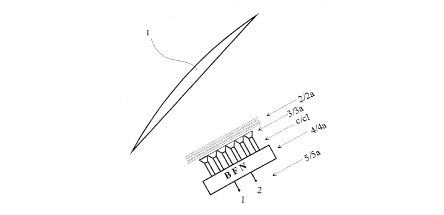
Antenne à faisceau modelé, comprenant un réflecteur simple ou double, avec ou sans grille, avec les faisceaux modelés, qui peut tourner la polarisation, indépendamment de la polarisation des grappes d'alimentation, destinée de préférence à une utilisation à bord des satellites. Champ d'application : satellites de télécommunication et domaines techniques : antennes à micro-ondes. L'antenne consiste en (Fig. 1) : un réflecteur (1), un ou plusieurs polariseurs (2), (2a), une ou plusieurs grappes d'alimentation (3), (3a), des circuits à micro-ondes (4), (4a) pour mettre en place le BFN, un port d'entrée (5), (5a), des connexions (C) et (C1) lesquelles, pour obtenir la configuration désirée de l'antenne, doivent être configurées comme suit : BFN mono ou multimodal ; des éléments d'alimentation rectangulaires (6) orientés selon la couverture requise des éléments d'alimentation (6) excités par le mode fondamental et des modes plus élevés ; un rotor de polarisation avec trois grilles ou plus ; un réflecteur parabolique ou peu modelé.


Abrégé anglais

Shaped beam antenna, with single or double reflector, gridded or non-gridded, with shaped beams,which can rotate the polarisation, independent of the polarisation of the feed cluster, for use preferably aboard satellites. Field of application: satellite telecommunications and technical field: micro-wave antennas. The antenna basically consists of (Fig. 1): a reflector (1), one or more polarisers (2), (2a), one or more feed clusters (3), (3a). microwave circuits (4), (4a) to set-up the BFN, input port (5), (5a), connections (C) and (C1) which to obtain the antenna configuration desired should be configured as follows: mono- or multimode BFN; rectangular feed elements (6) oriented according to the coverage required; feed elements excited by the fundamental mode plus some higher modes; polarisation rotator with three or more grids; parabolic or slightly shaped reflector.

Revendications

Note : Les revendications sont présentées dans la langue officielle dans laquelle elles ont été soumises.


8


The embodiments of the invention in which an exclusive
property or privilege is claimed are defined as follows:

1. An antenna comprising:
a reconfigurable multimode microwave beam forming network
(BFN);
a concave reflector separated from said BFN and providing a
shaped beam;
plural rectangular/square feed horn antennas that are arranged
in a cluster, connected to said BFN, and aligned to illuminate
said reflector to form the shaped beam;
means for exciting said antennas in the fundamental mode and
in the fundamental mode plus higher modes; and
at least one rotatable polarizer between said feed horn
antennas and said reflector and rotating an electric field so
that the direction of the electric field is parallel to a
direction of alignment of said feed horn antennas and
independent of the antenna's final polarization.
2. The antennas of claim 1, wherein said rotatable polarizer
comprises at least three grids.

Description

Note : Les descriptions sont présentées dans la langue officielle dans laquelle elles ont été soumises.


ANTENNA WITH 9INC~LE OR DOUBLE REFLECTORS, WITH SHAPED
HEAM9 AND LINEAR FOLARI9ATION
The invention presented is an antenna with single or
double reflectors, linear polarisation, shaped beams,
which can rotate the polarisation "arbitrarily", i.e.,
independent of the polarisation of the generating sys-
tem. It can be applied, preferably, in the field of
1~! telecommunications via satellite and in the scientific
field of telecommunications, more specifically in that
of micro-wave antennas.
c.
The most significant aspect of the invention is that in
1~ order to obtain a good shape of the antenna beam, th~
main reflector/subreflector should be illuminated by a
set of rectangular/square feed elements such that the
direction of the electrical field on their mouths is
parallel to the direction of alignment of said feed
elements. As will be explained below, this can be ob-
tained only if the polarisation is "reoriented" via a
polarises external to the groups of feed elements so as
not to vary the distribution of the electrical field
on the feed elements mouth.
~'1 C
... J


~~~~42$
2
The objective it is intended to achieve with this
invention is that of obtaining, with a single antenna
of this type, the performance provided by other types
of antenna, but not optimally, for example: performance
provided by antennas with shaped reflectors, fed by a
single feel, with single or double reflector; perform-
ance provided by antennas with parabolic reflectors
with feed clusters, etc., obtaining a greater or equal
1c! antenna gain for the same size of the principal reflec-
tors by deploying an antenna configuration which con-
silts of:
- reduced cluster ( for example from 8 to 11 feed ele-
ments) of rectangular multi-/single mode horns,;
1~ - parabolic or slightly shaped reflector.
Ifnown solutions which refer to antennas consisting of
feeds, rectangular or circular, concern the family
(which for convenience we will call family a) of para-
bolic-reflector antennas, slightly shaped, fed by a set
of feed elements, exhibiting a linear polarisation,
which can be either circular or rectangular. These
antennas can use mono- or multi-mode Heam Forming Net
t
works (BFN). Refer should be made to the following
~5 patents of the same Patentee for details on this:


3
No. RM94A 000005 filed on 07/01/1994 with the title:
" Multishaped beam direct radiating array antenna " and
No RM94A 000306 filed on 17/05/1994 with the title:
" Shaped-beam or scanned beams reflector or lens an-
tenna "
Another family (called for convenience family b) con-
sists of antennas with shaped reflectors fed by one or
more feed elements. However, using this solution, it is
difficult to realise multimode q~ntennas. Compared with
1« the antennas belonging to family a), the decoupling
between the polarisation and the feed cluster align
ment leads to a real improvement in performance in
t
terms of antenna~coverage gain,
The solution presented here arose from the need to
1~ obtain antenna gain values similar to those obtained by
the shaped reflector fed by a single feed or only ~a few
feeds. In fact, one of the advantages of the antenna
for which this patent is being filed, is the increase
in gain which can be obtained compared with other an
~« tennas of the same family a) having the same main
reflector diameter.
Compared with family b), the performance of the antenna
obtained are similar, such as for example the minimum
coverage gain, but in this case the advantage is
~S different. As a matter of fact the invention can be


~~~~2~
9
used to realise multimode antenna beams, for example
making it possible to use a non-adjacent interleaved
channel output multiplexes, with much lower losses,
realising multimode antenna beams by using the same
reflector.
Family a) was the first to come and was used for
about ten years. It was slowly replaced by family b)
because the latter achieves better gain performance
with the same diameter of the main reflector and also
1~~ because the feeds and HFN are lighter. On the down
side, family b) has some disadvantages, some of which
are listed below:
- difficulty in reconfiguring the antenna, i.e., chang-
ing the beam shape on command;
15 - difficulty in obtaining simultaneous multiple beams.
This invention therefore, as mentioned above, aims at
improving the type of antenna belonging to family aj
in terms of gain, increasing it to the values similar
to those of family b) while, however, maintaining the
most interesting characteristics of family a).
More specifically, the invention encompasses, in a
single solution, the advantages and properties of the
two families of antennas indicated here as a) and b).
Furthermore, the antenna, whose invention is being
~5 filed, can provide a better result (in the version


5
currently preferred by the inventor) if it consists of
the following elements:
- mono-/mult~imode HFN
- and/or reconfigurable array, i.e., an array which can
reconfigure all or part of HFN;
- rectangular/square feed(s), which, in addition to
being rectangular/square, are arranged in the "most
appropriate manner" to obtain the desired antenna pat-
tern;
- the feeds area typically excited by the fundamental
mode, plus other higher modes:
ex. (Te", 0 where n = 1, 2.... 5) ;
- polarisation rotator;
- parabolic or slightly shaped reflector;
1~ - possibly ellipsoid, hyperbolic or shaped sub-reflec-
tor; the reflector can also be gridded.
The expression "most appropriate manner" refers to the
orientation of the cluster of feed elements in accor-
dance with the orientation o~ the coverage. Said orien-
tation is chosen independently of the polarisation as
the presence of the external polarisation rotator al-
lows one to align the polarisation independently of the
alignment of the feed cluster.


6
The invention is now described, by way of illustration
and not limitation, refer being made to the attached
drawings and on the basis of the version of the inven-
tion currently preferred by the inventors.
Fig. 1 - Antenna layout showing:
- reflector (1);
- one or more polarisers (2), (2a);
- one or more feed clusters (3), (3a);
- micro-wave circuits (4), (4a) for the BFN,
1 s i - input ports ( 5 ) , ( 5a ) ;
- connections (C) and (C1).
Fig. 2 - Cluster of rectangular feed elements (6)
which are the most efficient system for shaping the
antenna beam, on condition that the polarisation is
15 parallel with the direction of alignment of the feed
elements.
Fig. 3 - Layout of a typical micro-wave circuit (BFN)
showing:
- hybrid dividers (7);
- fixed or variable phase shifter (8);
- fixed or variable power divider;
- switch (:LO) .
The HFNs can be either mono- or multimode, and can also
be reconfigured by adding to the circuit additional


S
1.
switches, variable power dividers and/or variable phase
shifters.
It is important to realise that as the polarisation is
parallel to the direction of alignment of the feed
5 elements, independent of the antenna's final polarisa
tion, it can be reoriented by the polarisation rotator
external to the feeds cluster.
To improve performance, the antenna, for which this
patent claim is being filed, should satisfy certain
1c.! specifications, namely it should consist:
- by a mono-/multimode HFN;
- by one or more rectangular/square feed elements (6)
which, in addition to being rectangular/square, are
arranged in the most appropriate manner to obtain the
1~ desired antenna pattern;
- by the feed elements which are excited by the funda-
t,
mental mode or by the fundamental mode plus some higher
modes.

Dessin représentatif
Une figure unique qui représente un dessin illustrant l'invention.
États administratifs

Pour une meilleure compréhension de l'état de la demande ou brevet qui figure sur cette page, la rubrique Mise en garde , et les descriptions de Brevet , États administratifs , Taxes périodiques et Historique des paiements devraient être consultées.

États administratifs

Titre Date
Date de délivrance prévu 2004-02-10
(22) Dépôt 1997-03-07
(41) Mise à la disponibilité du public 1997-09-13
Requête d'examen 2002-02-25
(45) Délivré 2004-02-10
Réputé périmé 2014-03-07

Historique d'abandonnement

Il n'y a pas d'historique d'abandonnement

Historique des paiements

Type de taxes Anniversaire Échéance Montant payé Date payée
Le dépôt d'une demande de brevet 300,00 $ 1997-03-07
Enregistrement de documents 100,00 $ 1997-05-05
Taxe de maintien en état - Demande - nouvelle loi 2 1999-03-08 100,00 $ 1999-03-03
Taxe de maintien en état - Demande - nouvelle loi 3 2000-03-07 100,00 $ 2000-02-29
Taxe de maintien en état - Demande - nouvelle loi 4 2001-03-07 100,00 $ 2001-03-02
Enregistrement de documents 50,00 $ 2001-06-26
Taxe de maintien en état - Demande - nouvelle loi 5 2002-03-07 150,00 $ 2002-02-13
Requête d'examen 400,00 $ 2002-02-25
Taxe de maintien en état - Demande - nouvelle loi 6 2003-03-07 150,00 $ 2003-02-20
Taxe finale 300,00 $ 2003-11-18
Taxe de maintien en état - brevet - nouvelle loi 7 2004-03-08 200,00 $ 2004-02-24
Taxe de maintien en état - brevet - nouvelle loi 8 2005-03-07 200,00 $ 2005-02-15
Enregistrement de documents 100,00 $ 2005-08-09
Enregistrement de documents 100,00 $ 2005-09-21
Taxe de maintien en état - brevet - nouvelle loi 9 2006-03-07 200,00 $ 2006-03-03
Taxe de maintien en état - brevet - nouvelle loi 10 2007-03-07 250,00 $ 2007-03-02
Taxe de maintien en état - brevet - nouvelle loi 11 2008-03-07 250,00 $ 2008-02-28
Taxe de maintien en état - brevet - nouvelle loi 12 2009-03-09 250,00 $ 2009-03-04
Taxe de maintien en état - brevet - nouvelle loi 13 2010-03-08 250,00 $ 2010-03-03
Taxe de maintien en état - brevet - nouvelle loi 14 2011-03-07 250,00 $ 2011-02-24
Taxe de maintien en état - brevet - nouvelle loi 15 2012-03-07 450,00 $ 2012-03-06
Titulaires au dossier

Les titulaires actuels et antérieures au dossier sont affichés en ordre alphabétique.

Titulaires actuels au dossier
SPACE ENGINEERING S.P.A.
FINMECCANICA S.P.A.
Titulaires antérieures au dossier
ALENIA SPAZIO S.P.A.
CAPECE, PASQUALE
FINMECCANICA S.P.A.
LABEN S.P.A.
LO FORTI, RAIMONDO
RUGGERINI, GIANFRANCO
Les propriétaires antérieurs qui ne figurent pas dans la liste des « Propriétaires au dossier » apparaîtront dans d'autres documents au dossier.
Documents

Pour visionner les fichiers sélectionnés, entrer le code reCAPTCHA :


Pour visualiser une image, cliquer sur un lien dans la colonne description du document. Pour télécharger l'image (les images), cliquer l'une ou plusieurs cases à cocher dans la première colonne et ensuite cliquer sur le bouton "Télécharger sélection en format PDF (archive Zip)" ou le bouton "Télécharger sélection (en un fichier PDF fusionné)".

Liste des documents de brevet publiés et non publiés sur la BDBC .

Si vous avez des difficultés à accéder au contenu, veuillez communiquer avec le Centre de services à la clientèle au 1-866-997-1936, ou envoyer un courriel au Centre de service à la clientèle de l'OPIC.


Description du
Document 
Date
(yyyy-mm-dd) 
Nombre de pages   Taille de l'image (Ko) 
Dessins représentatifs 1997-10-30 1 5
Revendications 2003-01-27 1 25
Page couverture 1997-10-30 1 58
Abrégé 1997-03-07 1 26
Description 1997-03-07 7 196
Dessins 1997-03-07 3 25
Revendications 1997-03-07 3 60
Page couverture 2004-01-07 1 41
Cession 2005-09-21 25 967
Cession 1997-03-07 4 137
Correspondance 1997-04-01 1 40
Cession 1997-05-05 2 99
Cession 2001-06-26 11 490
Correspondance 2001-08-28 1 14
Correspondance 2001-11-30 1 11
Correspondance 2002-03-22 1 13
Poursuite-Amendment 2002-02-25 1 43
Poursuite-Amendment 2002-07-11 3 66
Poursuite-Amendment 2002-09-25 2 53
Poursuite-Amendment 2003-01-27 3 107
Correspondance 2003-11-18 2 49
Cession 2005-08-09 102 4 391
Correspondance 2011-09-15 1 14
Correspondance 2011-09-09 1 31
Correspondance 2011-03-17 1 17