Sélection de la langue

Search

Sommaire du brevet 2199803 

Énoncé de désistement de responsabilité concernant l'information provenant de tiers

Une partie des informations de ce site Web a été fournie par des sources externes. Le gouvernement du Canada n'assume aucune responsabilité concernant la précision, l'actualité ou la fiabilité des informations fournies par les sources externes. Les utilisateurs qui désirent employer cette information devraient consulter directement la source des informations. Le contenu fourni par les sources externes n'est pas assujetti aux exigences sur les langues officielles, la protection des renseignements personnels et l'accessibilité.

Disponibilité de l'Abrégé et des Revendications

L'apparition de différences dans le texte et l'image des Revendications et de l'Abrégé dépend du moment auquel le document est publié. Les textes des Revendications et de l'Abrégé sont affichés :

  • lorsque la demande peut être examinée par le public;
  • lorsque le brevet est émis (délivrance).
(12) Brevet: (11) CA 2199803
(54) Titre français: CREPINE D'INCENDIE
(54) Titre anglais: SPRINKLER
Statut: Réputé périmé
Données bibliographiques
(51) Classification internationale des brevets (CIB):
  • A62C 31/05 (2006.01)
  • A62C 37/14 (2006.01)
  • B05B 1/14 (2006.01)
  • B05B 1/26 (2006.01)
  • B05B 1/34 (2006.01)
(72) Inventeurs :
  • SUNDHOLM, GORAN (Finlande)
(73) Titulaires :
  • MARIOFF CORPORATION OY (Finlande)
(71) Demandeurs :
  • SUNDHOLM, GORAN (Finlande)
(74) Agent: KIRBY EADES GALE BAKER
(74) Co-agent:
(45) Délivré: 2006-11-21
(86) Date de dépôt PCT: 1995-09-12
(87) Mise à la disponibilité du public: 1996-03-21
Requête d'examen: 2002-07-30
Licence disponible: S.O.
(25) Langue des documents déposés: Anglais

Traité de coopération en matière de brevets (PCT): Oui
(86) Numéro de la demande PCT: PCT/FI1995/000495
(87) Numéro de publication internationale PCT: WO1996/008291
(85) Entrée nationale: 1997-03-12

(30) Données de priorité de la demande:
Numéro de la demande Pays / territoire Date
944264 Finlande 1994-09-14

Abrégés

Abrégé français

L'invention concerne une crépine d'incendie comprenant, en mode d'attente, un dispositif de déclenchement (20) sensible à la chaleur et placé en contact étroit avec une tige (15). Afin d'assurer la régularité et la rectitude de la charge s'exerçant sur le dispositif de déclenchement (20), ainsi qu'une pulvérisation régulière du liquide d'extinction sous forme de brouillard liquide, la crépine d'incendie est caractérisée par le fait que la tige (15) est montée dans un canal (12) possédant une entrée (10) de liquide et une sortie (13) vers des buses placées, de préférence obliquement, et s'appuie contre la paroi dudit canal (12), de façon pratiquement ou totalement coulissante, des deux côtés de l'entrée (10) de liquide, afin d'équilibrer la pression du liquide au niveau de ladite entrée, quand la crépine d'incendie est en mode d'attente et qu'une buse (27) dirigée vers le centre par rapport aux buses placées obliquement, se trouve à l'extrémité de la tige (15) en face du dispositif de déclenchement (20).


Abrégé anglais


The present invention relates to a
sprinkler which in stand-by mode comprises
a heat-sensitive releasing device (20) in
close contact with a spindle (15). In
order to provide a new sprinkler which
ensures even and straight load on the
releasing device (20) and which also guarantees
even spreading of extinguishing liquid in the
form of liquid fog, the sprinkler is
characterized in that the spindle (15) is mounted
in a channel (12) with a liquid inlet (10)
and outlet (13) to preferably obliquely
positioned nozzles (14), and bears slidably or
almost slidably against the wall of the
channel (12) on both sides of the liquid inlet (10)
for balancing the liquid pressure at the
liquid inlet when the sprinkler is in stand-by
mode, and that a nozzle (27) centrally
directed in relation to the obliquely positioned
nozzles is provided at the end of the spindle
(15) which faces the releasing device (20).

Revendications

Note : Les revendications sont présentées dans la langue officielle dans laquelle elles ont été soumises.


6


CLAIMS:

1. A sprinkler comprising a body in which obliquely
positioned nozzles have been mounted, the body being
provided with a liquid inlet and a passage including a
channel with an inlet and an outlet for supplying
extinguishing medium to the obliquely positioned nozzles,
a spindle comprising a spindle channel and being
displaceably mounted in the channel of the passage,
wherein the spindle bears slidably or almost slidably
against a wall of the channel of the passage, a heat-
sensitive releasing device in close contact with the
spindle when the sprinkler is in standby mode, and a
centrally directed nozzle centrally directed in relation
to the obliquely positioned nozzles at an end of the
spindle which faces the releasing device, wherein the
spindle and the channel of the passage extend to both
sides of the inlet of the channel of the passage for at
least partial balancing of a liquid pressure at the inlet
of the channel of the passage when the sprinkler is in the
standby mode.
2. A sprinkler according to claim 1, and further
comprising a plug extending in the spindle channel and a
sealing between the inlet of the channel of the passage
and an inflow end when the sprinkler is in the standby
mode, wherein the spindle is arranged to be displaced so
that the connection from the inlet past the sealing to an
inflow end of the spindle channel is opened when the
sprinkler is released and wherein the centrally directed
nozzle is a direct extension of the spindle channel.


7


3. A sprinkler according to claim 2, wherein the sealing
between the inlet and a point of inflow of the spindle
channel comprises an annular sealing mounted on the plug.
4. A sprinkler according to claim 3, and further
comprising a spiral liquid channel defined by a coil
spring surrounding a nozzle pin in a lower portion of the
spindle channel.
5. A sprinkler according to claim 2, and further
comprising a spring in the spindle channel bearing partly
against a shoulder in the spindle channel and partly
against the plug to displace the spindle when the
sprinkler is released.
6. A sprinkler according to claim 5, and further
comprising a spiral liquid channel defined by a coil
spring surrounding a nozzle pin in a lower portion of the
spindle channel.
7. A sprinkler according to claim 2, and further
comprising a spiral liquid channel defined by a coil
spring surrounding a nozzle pin in a lower portion of the
spindle channel.
8. A sprinkler according to claim 1, wherein the
releasing device is provided with a holder having at least
one obliquely positioned spread surface outside an outlet
opening of the centrally directed nozzle.
9. A sprinkler according to claim 8, and further
comprising a spiral liquid channel defined by a coil


8


spring surrounding a nozzle pin in a lower portion of the
spindle channel.
10. A sprinkler according to claim 1, and further
comprising a spiral liquid channel defined by a coil
spring surrounding a nozzle pin in a lower portion of the
spindle channel.

Description

Note : Les descriptions sont présentées dans la langue officielle dans laquelle elles ont été soumises.


PCTlFI95/00495
WO 96/08291
1
Sprinkler
The present invention relates to a sprinkler
which in stand-by mode comprises a heat-sensitive
releasing device in close contact with a spindle. More
specifically, the invention relates to a sprinkler
comprising a body provided with at least one nozzle, a
liquid inlet and a passage for supplying extinguishing
medium to at least one nozzle, the sprinkler in stand-by
mode comprising a heat-sensitive releasing device in
close contact with a spindle displaceably mounted in a
liquid passage with an inlet and outlet to said nozzle.
The releasing device can be, for example, a
glass ampoule which breaks at an elevated temperature.
In order to ensure rapid release, it is desirable to
make the ampoule as thin as possible. Even a thin
ampoule resists a sufficiently heavy mechanical load if
the load is exerted directly on the end of the ampoule
and is even.
SE 501 267 discloses a sprinkler of this kind.
However, the known sprinkler does not allow a high
liquid pressure to prevail in the liquid inlet when the
sprinkler is in stand-by mode, and therefore rapid
release of the sprinkler is not possible. In this known
sprinkler, a high liquid pressure would exert such a
great force on the releasing device that the releasing
device would break or. In order to avoid breakage, the
releasing device should have a special construction.
The object of the present invention is to
provide a new sprinkler which ensures even and straight
load on the releasing device; the load is not so heavy
that the releasing device can break merely by the action
of the liquid pressure when the sprinkler is in stand-by
mode.


CA 02199803 2005-02-22
2
The sprinkler according to the invention is
characterized in that the liquid passage consists of a
channel against whose wall the spindle bears slidably or
almost slidably, said spindle and channel extending to
both sides of the inlet of the channel for at least
partial balancing of the liquid pressure at the inlet when
the sprinkler is in stand-by mode, and that a nozzle
centrally directed in relation to the obliquely positioned
nozzles is provided at that end of the spindle which faces
the releasing device.
Preferably, the sprinkler system of the present
invention comprises a plug extending in the spindle
channel and a sealing between the inlet of the channel of
the passage and an inflow end when the sprinkler is in the
standby mode, wherein the spindle is arranged to be
displaced so that the connection from the inlet past the
sealing to an inflow end of the spindle channel is opened
when the sprinkler is released and wherein the centrally
directed nozzle is a direct extension of the spindle
channel.
Preferably, the sealing between the inlet and a
point of inflow of the spindle channel comprises an
annular sealing mounted on the plug.
Preferably, the sprinkler system of the present
invention comprises a spiral liquid channel defined by a
coil spring surrounding a nozzle pin in a lower portion of
the spindle channel.
In the following, the invention will be
described in greater detail with reference to an
embodiment shown in the accompanying drawings, in which
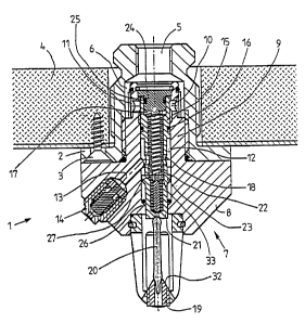
Figure 1 is a longitudinal section of an
embodiment of the invention in stand-by mode,

CA 02199803 2005-02-22
2a
Figure 2 shows the sprinkler of Figure 1 in
released mode.
Figure 3 is an end view of the sprinkler, seen
from below.
In Figures 1 and 2, reference numeral 1 denotes a
sprinkler. The sprinkler comprises a housing 2, which is
secured to a ceiling 4 by a plurality of screws 3; the
housing 2 is provided with a liquid inlet 5, which extends
through the ceiling 4 and continues as a central
channel 6. The sprinkler is further provided with an
insert 7 comprising a housing 8 which is attached to the
sprinkler housing 2, for instance, by means of a head 9
screwed in the Central channel 6 and tightened against it.
The combination of sprinkler housing 2 on insert housing 8
may be referred to as the sprinkler body.
The head 9 of the insert housing 8 comprises a
plurality of inlet openings 10 which are connected through
a filter 11 to the liquid inlet 5 and which lead to a
central channel 12 in the head 9. The central


WO 96/08291 PCTlF195100495
3
channel 12 branches off through branchings 13 to a
plurality of obliquely positioned nozzles 14. A spindle
15 is slidably mounted in the central channel 12 of the
insert housing 8. When the sprinkler is in stand-by
mode, as shown in Figure 1, the spindle 15 is sealed
against the head 9 by means of a sealing 16 below the
liquid inlet openings 10. The central channel 12 extends
to both sides of the liquid inlet openings 10 to prevent
the liquid pressure from exerting too great a downward
force on the spindle 15 when the sprinkler is in stand-
by mode.
The spindle 15 is also provided with a central
channel 17 (hereafter: spindle channel) which below the
spindle sealing 16 is connected via openings 18 to the
central channel 12 of the head 9 and therefrom via the
branchings 13 to the nozzles 14.
A holder 19 for a releasing device 20, e.g. an
ampoule of a heat-sensitive glass-like material which
softens and/or melts at an elevated temperature, is
mounted on the bottom of the insert housing 8. The inner
end of the ampoule 20 is fitted into the outer end
portion 21 of the spindle 15, through which it is loaded
by a spring 22 provided in the central channel of the
spindle. The end of the spring 22 that faces the ampoule
20 bears against the bottom of the spindle channel 17
at a shoulder 33, whereas its opposite end bears against
a plug 24 which is mounted in the head and sealed
against the inside of the spindle channel 17 by means
of an annular sealing 25. Alternatively, the shoulder
33 can be positioned higher in the spindle channel 17,
and an adjustable stopper can be used instead of the
plug 24.
The force of the spring 22 and the (typically
very small ) annular area of the sealing 16, on which the
liquid pressure acts at the inlet openings 10, are


i
WO 96108291 PCT/FI95100495
4
dimensioned in such a manner that they do not break the
ampoule 20 when its temperature is normal in stand-by
mode as shown in Figure 1. If the part of the spindle
15 that is located above the sealing 16 is in close
contact with the surrounding wall of the head 9 on both
sides of the inlet openings 10, the liquid pressure is
in complete balance; only the spring 22 presses the
spindle.
In stand-by mode illustrated in Figure 1, there
is, because of sealing 25, no liquid connection from the
inlet openings 10 through the upper end of the spindle
channel 17 to the nozzles 14; the direct connection is
closed by sealing 16.
If the ampoule 20 breaks or at least softens
because of hot gases or active heating by means of a
heating coil (not shown) and yields under the force of
the spring 22, as shown in Figure 2, the spindle 15
strikes down until a shoulder 23 provided on said
spindle interlocks tightly with a shoulder 26 provided
in the insert housing 8. The spindle 15 moves a suffi-
ciently long way to provide a connection for the liquid
from the inlet openings 10 through the channel 12 in the
head 9 past the sealing 25 to the spindle channel 17 and
further to the nozzles 14 via openings 18 in the spindle
15. The nozzles 14 are preferably of such a type that
they operate under high pressure and spray penetrating
extinguishing liquid in the form of liquid fog in
accordance with, for example, patent application
PCT/FI92/00155.
Before the insert 7 is mounted, the ampoule 20
and the spindle construction 15, including the spring
22, are positioned in the insert housing 8. Thereafter
the insert 7 is mounted in its entirety. It is thus easy
to carry out careful mounting without damaging the
ampoule, which is sensitive to shocks and uneven load.


W~ 96/08291 PCT/FI95/00495
The outer end portion 21 of the spindle 15,
i.e. the end which faces the ampoule 20, is provided
with a nozzle 27 having preferably the same basic con-
struction as the nozzles 14 with a coil spring 28 around
5 a nozzle pin 29. In the released position shown in
Figure 2, the liquid, in addition to flowing out through
the nozzles 14, also flows from the spindle channel 17
through openings 30 in between and along the spirals of
the spring 28 through a nozzle opening 31 and spreads
through oblique spread surfaces 32 provided at the outer
end of the holder 19.
The central nozzle 27 at the end of the spindle
ensures that there is no "hole" in the liquid fog
produced by the sprinkler.

Dessin représentatif
Une figure unique qui représente un dessin illustrant l'invention.
États administratifs

Pour une meilleure compréhension de l'état de la demande ou brevet qui figure sur cette page, la rubrique Mise en garde , et les descriptions de Brevet , États administratifs , Taxes périodiques et Historique des paiements devraient être consultées.

États administratifs

Titre Date
Date de délivrance prévu 2006-11-21
(86) Date de dépôt PCT 1995-09-12
(87) Date de publication PCT 1996-03-21
(85) Entrée nationale 1997-03-12
Requête d'examen 2002-07-30
(45) Délivré 2006-11-21
Réputé périmé 2014-09-12

Historique d'abandonnement

Il n'y a pas d'historique d'abandonnement

Historique des paiements

Type de taxes Anniversaire Échéance Montant payé Date payée
Le dépôt d'une demande de brevet 150,00 $ 1997-03-12
Taxe de maintien en état - Demande - nouvelle loi 2 1997-09-12 50,00 $ 1997-08-20
Taxe de maintien en état - Demande - nouvelle loi 3 1998-09-14 100,00 $ 1998-09-01
Taxe de maintien en état - Demande - nouvelle loi 4 1999-09-13 100,00 $ 1999-08-16
Taxe de maintien en état - Demande - nouvelle loi 5 2000-09-12 150,00 $ 2000-08-15
Taxe de maintien en état - Demande - nouvelle loi 6 2001-09-12 150,00 $ 2001-08-21
Enregistrement de documents 50,00 $ 2001-09-26
Requête d'examen 400,00 $ 2002-07-30
Taxe de maintien en état - Demande - nouvelle loi 7 2002-09-12 150,00 $ 2002-08-22
Taxe de maintien en état - Demande - nouvelle loi 8 2003-09-12 150,00 $ 2003-08-21
Taxe de maintien en état - Demande - nouvelle loi 9 2004-09-13 200,00 $ 2004-08-25
Taxe de maintien en état - Demande - nouvelle loi 10 2005-09-12 250,00 $ 2005-08-25
Taxe finale 300,00 $ 2006-07-12
Taxe de maintien en état - Demande - nouvelle loi 11 2006-09-12 250,00 $ 2006-08-31
Taxe de maintien en état - brevet - nouvelle loi 12 2007-09-12 250,00 $ 2007-08-21
Taxe de maintien en état - brevet - nouvelle loi 13 2008-09-12 250,00 $ 2008-08-13
Taxe de maintien en état - brevet - nouvelle loi 14 2009-09-14 250,00 $ 2009-09-01
Taxe de maintien en état - brevet - nouvelle loi 15 2010-09-13 450,00 $ 2010-08-23
Taxe de maintien en état - brevet - nouvelle loi 16 2011-09-12 450,00 $ 2011-09-06
Taxe de maintien en état - brevet - nouvelle loi 17 2012-09-12 450,00 $ 2012-08-08
Titulaires au dossier

Les titulaires actuels et antérieures au dossier sont affichés en ordre alphabétique.

Titulaires actuels au dossier
MARIOFF CORPORATION OY
Titulaires antérieures au dossier
SUNDHOLM, GORAN
Les propriétaires antérieurs qui ne figurent pas dans la liste des « Propriétaires au dossier » apparaîtront dans d'autres documents au dossier.
Documents

Pour visionner les fichiers sélectionnés, entrer le code reCAPTCHA :


Pour visualiser une image, cliquer sur un lien dans la colonne description du document. Pour télécharger l'image (les images), cliquer l'une ou plusieurs cases à cocher dans la première colonne et ensuite cliquer sur le bouton "Télécharger sélection en format PDF (archive Zip)" ou le bouton "Télécharger sélection (en un fichier PDF fusionné)".

Liste des documents de brevet publiés et non publiés sur la BDBC .

Si vous avez des difficultés à accéder au contenu, veuillez communiquer avec le Centre de services à la clientèle au 1-866-997-1936, ou envoyer un courriel au Centre de service à la clientèle de l'OPIC.


Description du
Document 
Date
(yyyy-mm-dd) 
Nombre de pages   Taille de l'image (Ko) 
Description 1997-03-12 5 193
Dessins 1997-03-12 2 81
Abrégé 1997-03-12 1 69
Revendications 1997-03-12 2 68
Page couverture 1997-09-05 1 46
Dessins représentatifs 2004-08-26 1 23
Description 2005-02-22 6 216
Revendications 2005-02-22 3 83
Page couverture 2006-10-20 1 58
Cession 1997-03-12 5 138
PCT 1997-03-12 11 349
Cession 2001-09-26 3 130
Poursuite-Amendment 2002-07-30 1 41
Poursuite-Amendment 2005-02-22 7 205
Poursuite-Amendment 2004-08-26 3 109
Poursuite-Amendment 2005-03-04 2 90
Correspondance 2006-07-12 1 38