Sélection de la langue

Search

Sommaire du brevet 2200331 

Énoncé de désistement de responsabilité concernant l'information provenant de tiers

Une partie des informations de ce site Web a été fournie par des sources externes. Le gouvernement du Canada n'assume aucune responsabilité concernant la précision, l'actualité ou la fiabilité des informations fournies par les sources externes. Les utilisateurs qui désirent employer cette information devraient consulter directement la source des informations. Le contenu fourni par les sources externes n'est pas assujetti aux exigences sur les langues officielles, la protection des renseignements personnels et l'accessibilité.

Disponibilité de l'Abrégé et des Revendications

L'apparition de différences dans le texte et l'image des Revendications et de l'Abrégé dépend du moment auquel le document est publié. Les textes des Revendications et de l'Abrégé sont affichés :

  • lorsque la demande peut être examinée par le public;
  • lorsque le brevet est émis (délivrance).
(12) Brevet: (11) CA 2200331
(54) Titre français: JEU DE CUBES EMPILABLES
(54) Titre anglais: A STACKABLE BLOCK SYSTEM
Statut: Réputé périmé
Données bibliographiques
(51) Classification internationale des brevets (CIB):
  • A63H 33/08 (2006.01)
(72) Inventeurs :
  • FREDERIKSEN, JESPER BO (Danemark)
(73) Titulaires :
  • INTERLEGO AG (Suisse)
(71) Demandeurs :
  • INTERLEGO AG (Suisse)
(74) Agent: FETHERSTONHAUGH & CO.
(74) Co-agent:
(45) Délivré: 2005-05-03
(86) Date de dépôt PCT: 1995-09-28
(87) Mise à la disponibilité du public: 1996-04-04
Requête d'examen: 2002-08-08
Licence disponible: S.O.
(25) Langue des documents déposés: Anglais

Traité de coopération en matière de brevets (PCT): Oui
(86) Numéro de la demande PCT: PCT/DK1995/000389
(87) Numéro de publication internationale PCT: WO1996/009870
(85) Entrée nationale: 1997-03-18

(30) Données de priorité de la demande:
Numéro de la demande Pays / territoire Date
1121/94 Danemark 1994-09-29

Abrégés

Abrégé français

Le jeu de cubes empilables de la présente invention est constitué de cubes empilables comportant un corps présentant sur sa face supérieure des pions d'assemblage caractérisés par un écartement modulaire mutuel uniforme. Le corps de cube présente en outre, des structures d'assemblage orientées vers le bas, lesquelles structures d'assemblage sont complémentaires des pions d'assemblage de la face supérieure, et sont conçues pour s'assembler avec les pions d'assemblage. Selon la présente invention, les cubes comportent en complément une ou plusieurs cales de butée orientées vers le bas. Grâce à ces cales de butée, lorsque deux cubes empilables sont empilés l'un sur l'autre, les parties constituant le corps des cubes empilables restent séparées l'une de l'autre sur l'ensemble de leur périmètre. On dispose ainsi d'un bord de préhension ou d'un intervalle entre les deux cubes empilés l'un sur l'autre, ce qui facilite particulièrement la préhension des cubes pour désassembler les cubes d'une pile.


Abrégé anglais


A stacking block system having stacking
blocks which have a body part which is
provided with coupling knobs with a mutual
uniform modular distance on its upper
side and is downwardly provided with coupling
means which are complementary with
respect to the coupling knobs on the upper
side and are adapted to be coupled with the
coupling knobs. According to the invention,
the blocks are additionally provided with one
or more spacers downwardly, which are designed
such that when two stacking blocks
are stacked on top of each other, the body
parts of the stacking blocks will be spaced
from each other along their entire periphery.
This provides a gripping edge or a gap
between two blocks stacked on top of each
other, so that it is particularly easy to grip
the blocks when a stack of such blocks is to
be separated.

Revendications

Note : Les revendications sont présentées dans la langue officielle dans laquelle elles ont été soumises.


8


CLAIMS:


1. A stacking block system comprising stacking blocks
each having a body part which, on its upper side, is
provided with a number of coupling knobs having a mutual
uniform modular separation distance, and is downwardly
provided with complementary coupling means adapted to be
coupled with coupling knobs of another of said blocks,
wherein the blocks have one or more spacers extending below
the body part of the blocks, the spacers being designed such
that when two stacking blocks are stacked on top of each
other the body parts of the stacking blocks will be spaced
from one another along their entire periphery, and wherein
the height of the coupling knobs above the body parts is
greater than the distance between the body parts of the
stacking blocks when the stacking blocks are stacked.

2. A stacking block system according to claim 1,
wherein the distance between the body parts is greater than
3 mm.

3. A stacking block system according to claim 1
wherein the spacers are provided as part of the
complementary coupling means.

4. A stacking block system according to claim 1,
wherein the complementary coupling means are formed by
cylindrical coupling tubes and that the coupling knobs
comprise large coupling knobs having an outer shape which
fits in the cylindrical coupling tubes when the blocks are
stacked.

5. A stacking block system according to claim 4,
wherein the system further comprises blocks provided with
small coupling knobs which are arranged in a square pattern


9

having a mutual modular separation distance and a diameter
such that precisely four of the small coupling knobs are
surrounded by a cylindrical coupling tube when the blocks
are stacked.

6. A stacking block system according to claim 5,
wherein the modular separation distance between the large
coupling knobs is three times the modular separation
distance between the small coupling knobs.

7. A stacking block system according to claim 6,
wherein it comprises stacking blocks having a substantially
box-shaped body part with outer transverse dimensions
corresponding to an integer multiple of the modular distance
between the large coupling knobs, and that the small
coupling knobs have a height above the body part of the
stacking block which is smaller than the distance between
the body parts of the stacking blocks upon stacking.

8. A stacking block system according to claim 7,
wherein the coupling knobs and the cylindrical coupling
tubes are dimensioned so as to provide a frictional coupling
between the small coupling knobs, the large coupling knobs
and the cylindrical coupling tubes when the blocks are
stacked.


Description

Note : Les descriptions sont présentées dans la langue officielle dans laquelle elles ont été soumises.

CA 02200331 2002-08-22
22903-668
1
A stackable block system
The present invention concerns a stacking block
system comprising stacking blocks each having a body part
which is provided with one coupling knob or a plurality of
coupling knobs with a mutual firm modular distance on its
upper side and is downwardly provided with complementary
coupling means adapted to be coupled with coupling knobs of
another of said blocks.
Such stacking block systems or building block
systems are available in numerous different embodiments,
which are frequently specially designed for the building of
structures of different types. Since these known systems
are frequently designed such that there are no gaps between
two blocks which are stacked on top of each other, these
blocks can be separated only by pulling or twisting off the
blocks from above.
If a wall or a column of a certain dimension is
built, it is extremely difficult to separate the blocks e.g.
at the center of the wall or the column.
The object of the present invention is to provide
a stacking block system which, to a higher degree than the
known ones, provides blocks which are simple to separate, in
particular for small children, i.e. children under 2-3 years
of age.
According to the invention there is provided a
stacking block system comprising stacking blocks each having
a body part which, on its upper side, is provided with a
number of coupling knobs having a mutual uniform modular
separation distance, and is downwardly provided with
complementary coupling means adapted to be coupled with


CA 02200331 2002-08-22
22903-668
2
coupling knobs of another of said blocks, wherein the blocks
have one or more spacers extending below the body part of
the blocks, the spacers being designed such that when two
stacking blocks are stacked on top of each other the body
parts of the stacking blocks will be spaced from one another
along their entire periphery, and wherein the height of the
coupling knobs above the body parts is greater than the
distance between the body parts of the stacking blocks when
the stacking blocks are stacked.
The spaces provide a recess or a gripping edge
which ensures that e.g. the fingers of a child can easily
catch hold of the lower edge of a given stacking block, also
even if the stacking block concerned should be present in
the center of a constructed wall or column or the like.
The distance between the body parts is expediently
greater than 3 mm, so that the recess established between
the body parts on two stacking blocks stacked on top of each
other serves extremely well as a gripping edge for the hand
of a child of the above-mentioned age.
The spacers establishing the distance between two
stacking blocks upon stacking, may be provided as elements
having just this function but in a preferred embodiment the
spacers form part of the complementary coupling means. The
coupling knobs and the complementary coupling means may be
provided in many ways.
The large coupling knobs may expediently have a
mutual modular distance which is three times greater than
the modular distance between the small coupling knobs. This
ensures a high degree of compatibility between the coupling
knobs, thereby providing increased play value since the
stacking blocks may be stacked arbitrarily on top of each


CA 02200331 2002-08-22
22903-668
3
other irrespective of which coupling knobs are present on
the individual stacking block.
In an expedient embodiment of the invention, the
stacking blocks have a substantially box-shaped body part
with outer transverse dimensions corresponding to an integer
multiple of the modular distance between the large coupling
knobs, and wherein the small coupling knobs have a height
above the body part of the stacking block which is smaller
than the distance between the body parts of the stacking
blocks when stacked. This ensures additionally increased
compatibility, since the box-shaped body part on the
stacking block, even though it partly covers a row of the
small coupling knobs, does not prevent the stacking block
from being placed on a building plate having a large number
of small coupling knobs in a square pattern.
In a particularly expedient embodiment, the play
value of the stacking block system is particularly great,
since a frictional coupling is provided between the small
coupling knobs and the cylindrical coupling tubes, while no
friction occurs when the cylindrical coupling tubes and the
large coupling knobs are coupled. This provides a varied
degree of difficulty for the stacking of the blocks, it
being extremely simple to stack blocks on the large coupling
knobs without friction, but somewhat more difficult to stack
blocks on the small coupling knobs with friction. The
visual difference between the large and the small coupling
knobs additionally gives the child, who plays with the
stacking blocks, the possibility of selecting the degree of
difficulty in a simple manner.


WO 96/09870 2 2 0 0 3 31 PCT/DK95/00389
- 4 -
Embodiments of the invention will be described more fully
below with reference to the drawing, in which:
fig. 1 is a perspective view, obliquely from above, of an
embodiment of a stacking block according to the invention.
Fig. 2 is a perspective view, obliquely from above, of
another embodiment of a stacking block according to the
invention.
Fig. 3 is a perspective view, obliquely from below, of the
stacking block of fig. 1 or fig. 2.
Fig. 4 is a perspective view, obliquely from below, of two
stacking blocks according to the invention stacked on each
other.
Fig. 5 is a sectional top view of a stacking block of fig.
4, placed on a building plate.
Fig. 6 is a lateral view of the building plate and the
stacking block of fig. 5.
Fig. 7 is a perspective view, obliquely from above, of an
alternative embodiment of a stacking block according to
the invention with wheels.
Fig. 8 is an oblique bottom view of the stacking block of
fig. 7.
Fig. 1 thus shows a stacking block 1 having a single knob '
2. The knob 2 is provided centrally on the box-shaped body
part 3. The box-shaped body part 3 is defined by four side '
faces 4. The knob 2 is downwardly shaped as a circular
symmetrical cylinder, optionally with a slight cone which
narrows the knob 2 upwardly. The top face of the knob 2 is


WO 96/09870 PCT/DK95/00389
0331
- 5 -
here shaped as part of a ball shell, thereby imparting an
appearance with very round shapes to the knob. The very
round shapes on the knob 2 hereby provide a good gripping
face for a child's hand, while there are no sharp edges
which may be unpleasant to step on, fall on or the like.
Fig. 2 shows another stacking block 5 according to the
invention, which has a box-shaped body part 3 like the
stacking block 1 shown in fig. 1. The stacking block 5
shown in fig. 2 differs from the stacking block 1 of fig.
1 only in that it is provided with four small coupling
knobs 6.
Fig. 3 shows the stacking block 5 of fig. 2 from below. It
will be seen that the stacking block 5 is hollow interior-
ly and is provided with a coupling tube 7, which is stif-
fened with respect to the side walls 4 by means of ribs 8
provided for the purpose. This embodiment is particularly
simple to produce in an injection moulding process.
The coupling tube 7, which is seen in fig. 3, has a dia-
meter enabling the coupling tube 7 to be lowered over the
coupling knob 2 on the stacking block 1 in fig. 1 or over
the four small coupling knobs 6 on the stacking block 5 of
fig. 2. This enables stacking of several such blocks.
As will be seen in fig. 3, the coupling tube 7 extends
beyond the box-shaped body part which is surrounded by the
side walls 4. This means that when the blocks are stacked
on each other, the box-shaped body parts 3 on the stacking
blocks will be spaced from each other.
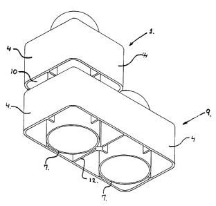
This is illustrated in fig. 4, which shows a stacking
block 9 twice as big as the stacking blocks in figs. 1-3,
a stacking block 1 of the type shown in fig. 1 being
placed on the stacking block 9. As will be seen, this re-


~. . ~ y2
~03~31~
- 6 -
a stacking block 1 of the type shown in fig. 1 being
placed on the stacking block 9. As will be seen, this re-
sults in a gap 10 between the stacking block 9 and the
stacking block 1, having a width corresponding to the dis-
tance which the coupling tube 7 of fig. 3 protrudes from
the body part on the stacking block which is defined by
the side faces 4. This provides a gripping edge, which
makes it extremely easy to grip the stacking block 1 at
the gap 10, so that the stacking block 1 may be lifted
from the lowermost stacking block 9~ as shown in fig. 4:
Figs. 5 and 6 illustrate further advantages of the present
invention, showing how it is possible to combine coupling
systems with different modular distances. Thus, fig. 5
shows a building plate 11 which is provided with coupling
knobs 6, here shown with four rows each having seven coup-
ling knobs 6. These coupling knobs 6 correspond to the
coupling knobs 6 on the stacking block 5 shown in fig. 2.
The shape of a cross-section of the stacking block 9 shown
in fig. 4 is drawn in thick line, and it will be seen how
the side walls 4 and the inner flange 12 intersect the
coupling knobs 6 on the building plate 11. However, since
a gap 10 is provided between the coupling plate 11 and the
stacking block 9, it is nevertheless possible to intercon-
nect these, because the gap IO is wider than the height of
the coupling knobs 6 on the building plate 11.
According to the invention, the gap between the stacking
blocks may be established in other ways than by extending
the coupling tube 7 below the body parts of the stacking
blocks. Thus, figs. 7 and 8 show an alternative embodiment
of a stacking block comprising a base member 13 which sub-
stantially corresponds to the stacking block 9 of fig. 4.
As will be seen in figs. 7 and 8, the base member 13 is
provided with four wheels 14. If the coupling tubes 7,
P~~NO


WO 96/09870 ~ 2 0 0 3 31 PCT~~~/00389
wheels. Therefore, the interior of the coupling tubes 7 is
formed with flanges 15 which, upon stacking on another
block having large coupling knobs, e.g. the one shown in
fig. 1, engage the surface of the coupling knobs 2 and en-
surs the provision of a gap between these.
Thus, a gap between two stacking blocks according to the
invention may be provided in many different ways, and it
is obvious to a skilled person to teach a very large num-
ber of such possible variations. In addition, the shown
embodiments of the invention may be varied to a great ex-
tent, both as regards the shape of the stacking blocks,
the number of knobs and the like, and as regards selection
of material.
20
30

Dessin représentatif
Une figure unique qui représente un dessin illustrant l'invention.
États administratifs

Pour une meilleure compréhension de l'état de la demande ou brevet qui figure sur cette page, la rubrique Mise en garde , et les descriptions de Brevet , États administratifs , Taxes périodiques et Historique des paiements devraient être consultées.

États administratifs

Titre Date
Date de délivrance prévu 2005-05-03
(86) Date de dépôt PCT 1995-09-28
(87) Date de publication PCT 1996-04-04
(85) Entrée nationale 1997-03-18
Requête d'examen 2002-08-08
(45) Délivré 2005-05-03
Réputé périmé 2007-09-28

Historique d'abandonnement

Il n'y a pas d'historique d'abandonnement

Historique des paiements

Type de taxes Anniversaire Échéance Montant payé Date payée
Le dépôt d'une demande de brevet 300,00 $ 1997-03-18
Enregistrement de documents 100,00 $ 1997-04-14
Taxe de maintien en état - Demande - nouvelle loi 2 1997-09-29 100,00 $ 1997-07-28
Taxe de maintien en état - Demande - nouvelle loi 3 1998-09-28 100,00 $ 1998-09-10
Taxe de maintien en état - Demande - nouvelle loi 4 1999-09-28 100,00 $ 1999-09-10
Taxe de maintien en état - Demande - nouvelle loi 5 2000-09-28 150,00 $ 2000-08-17
Taxe de maintien en état - Demande - nouvelle loi 6 2001-09-28 150,00 $ 2001-08-03
Taxe de maintien en état - Demande - nouvelle loi 7 2002-09-30 150,00 $ 2002-08-06
Requête d'examen 400,00 $ 2002-08-08
Taxe de maintien en état - Demande - nouvelle loi 8 2003-09-29 150,00 $ 2003-08-07
Taxe de maintien en état - Demande - nouvelle loi 9 2004-09-28 200,00 $ 2004-08-05
Taxe finale 300,00 $ 2005-02-16
Taxe de maintien en état - brevet - nouvelle loi 10 2005-09-28 250,00 $ 2005-08-05
Titulaires au dossier

Les titulaires actuels et antérieures au dossier sont affichés en ordre alphabétique.

Titulaires actuels au dossier
INTERLEGO AG
Titulaires antérieures au dossier
FREDERIKSEN, JESPER BO
Les propriétaires antérieurs qui ne figurent pas dans la liste des « Propriétaires au dossier » apparaîtront dans d'autres documents au dossier.
Documents

Pour visionner les fichiers sélectionnés, entrer le code reCAPTCHA :


Pour visualiser une image, cliquer sur un lien dans la colonne description du document. Pour télécharger l'image (les images), cliquer l'une ou plusieurs cases à cocher dans la première colonne et ensuite cliquer sur le bouton "Télécharger sélection en format PDF (archive Zip)" ou le bouton "Télécharger sélection (en un fichier PDF fusionné)".

Liste des documents de brevet publiés et non publiés sur la BDBC .

Si vous avez des difficultés à accéder au contenu, veuillez communiquer avec le Centre de services à la clientèle au 1-866-997-1936, ou envoyer un courriel au Centre de service à la clientèle de l'OPIC.


Description du
Document 
Date
(yyyy-mm-dd) 
Nombre de pages   Taille de l'image (Ko) 
Page couverture 1997-09-11 1 53
Dessins représentatifs 1997-09-11 1 7
Abrégé 1997-03-18 1 61
Description 1997-03-18 7 295
Revendications 1997-03-18 3 97
Dessins 1997-03-18 4 75
Description 2002-08-22 7 283
Revendications 2002-08-22 2 74
Dessins représentatifs 2004-08-12 1 9
Page couverture 2005-04-07 1 42
Correspondance 2005-02-16 1 33
Cession 1997-03-18 5 214
PCT 1997-03-18 11 434
Correspondance 1997-04-22 1 40
Cession 1997-04-29 1 35
Cession 1997-04-14 2 69
Poursuite-Amendment 2002-08-08 1 43
Poursuite-Amendment 2002-08-22 7 246