Note : Les descriptions sont présentées dans la langue officielle dans laquelle elles ont été soumises.
225~
--1--
DESCRIPTION
Nozzle Plate for Filling Liquid
Technical Field:
The present invention relates to a liquid filling
nozzle plate used to fill a container with a liquid.
Background Art:
Conventionally, liquid filling apparatuses have been
developed and used for automatically filling containers with
liquids, e.g. milk and juice.
Fig. 10 is a sectional side view schematically showing
an essential part of a liquid filling apparatus of the type
described above. As shown in the figure, the liquid filling
apparatus is arranged as follows: A pipe 61 is connected to
the bottom of a liquid tank 60, and two check valves 63 and
65 are installed in the pipe 61. Further, a liquid filling
tube 67 is attached to a portion of the pipe 61 below the
check valves 63 and 65, while a pipe 69 is connected to a
portion of the pipe 61 between the two check valves 63 and
65, and a liquid volumetric discharge machine 71 is attached
to the lower end of the pipe 69.
Both the two check valves 63 and 65 are resiliently
biased upwardly by respective coil springs 64 and 66 so that
a liquid can be led only downwardly.
The liquid volumetric discharge machine 71 has a
cylinder 73 and a piston 75 vertically movably received in
22~084~
the cylinder 73. The vertical stroke of the piston 75 is
fixed.
A liquid filling nozzle plate 80 is attached to the
lower end opening of the liquid filling tube 67.
Figs. ll(a) and ll(b) show the conventional liquid
filling nozzle plate 80. Fig. ll(a) is a plan view, and
Fig. ll(b) is a front view. As shown in the figures, the
liquid filling nozzle plate 80 is formed from a metallic
disk 81 provided with a large number of through-holes 83.
There is another conventional nozzle plate consisting
of a sieve plate formed from a wire net. This nozzle plate
is constructed of a wire net formed by weaving a plurality
of longitudinal and lateral metal wires. In this nozzle
plate, through-holes are formed in the gaps between the
wires.
Next, the operation of the liquid filling apparatus
will be described by using mainly Fig. 10. First, the
liquid in the liquid tank 60 fills a part extending from the
top of the pipe 61 to the end of the liquid filling tube 67
and a part extending from the top of the pipe 69 to the top
of the piston 75.
When the piston 75 is pushed down in the direction of
the arrow A, the check valve 63 opens, and the liquid in the
liquid tank 60 is introduced into the liquid volumetric
discharge machine 71.
Then, when the piston 75 is pushed up in the direction
of the arrow B, the check valve 63 is closed, while the
check valve 65 opens. Consequently, the liquid in the
~2 ~0840
liquid volumetric discharge machine 71 is passed through the
liquid filling tube 67 and discharged from the through-holes
83 of the liquid filling nozzle plate 80, thereby being
supplied into a container (not shown).
The liquid filling nozzle plate 80 is provided to
prevent the liquid filling the liquid filling tube 67 from
flowing out (so-called dripping) when no liquid is desired
to discharge from the liquid filling nozzle plate 80.
More specifically, the surface tension of the liquid
filling the liquid filling tube 67 acts in the large number
of through-holes 83 provided in the liquid filling nozzle
plate 80, thereby preventing the liquid from flowing out by
gravity. Thus, dripping of liquid is prevented.
However, the through-holes 83 provided in the
conventional liquid filling nozzle plate 80 are so shaped
that, as shown in the sectional view of Fig. 12, the inner
surfaces 85 of the through-holes 83 extend straight in the
vertical direction.
Therefore, the surface tension acting in the through-
holes 83 is not satisfactorily high, so that dripping ofliquid is likely to occur. To increase the surface tension
in order to prevent dripping of liquid, the diameters of the
through-holes 83 may be reduced. However, if the diameters
of the through-holes 83 are reduced, the fluid resistance
occurring when the liquid is discharged increases
undesirably.
In contrast, the wire-net sieve plate provides
relatively large surface tension owing to the complicated
220084u
surface configuration of the openings and is therefore
capable of effectively preventing dripping of liquid. With
the wire-net sieve plate, however, solid matters in the
filling liquid, e.g. fibers and fruit flesh, may be
entangled or caught in the intersections of the wires,
causing the sieve plate to be clogged. Moreover, because
the sieve plate is a wire net, the mechanical strength is
low.
In view of the above-described circumstances, an object
of the present invention is to provide a liquid filling
nozzle plate capable of effectively preventing dripping of
liquid without the need to reduce the diameters of through-
holes.
Another object of the present invention is to provide a
liquid filling nozzle plate capable of effectively
preventing dripping of liquid without causing the holes to
be clogged with solid matter in the filling liquid.
Still another object of the present invention is to
provide a liquid filling nozzle plate having high mechanical
strength.
Disclosure of Invention:
To attain the above-described objects, the present
invention provides a liquid filling nozzle plate comprising
a plate member provided with a large number of through-
holes, the nozzle plate being attached to the lower end
opening of a liquid filling tube to prevent a liquid filling
the liquid filling tube from flowing out by the surface
~20~4ù
tension of the liquid, wherein the inner peripheral surface
of each of the through-holes provided in the liquid filling
nozzle plate is provided with a circumferential projection
projecting in a direction in which the inner diameter of the
through-hole is reduced.
In addition, the present invention provides a liquid
filling nozzle plate comprising a plate member provided with
a large number of through-holes, the nozzle plate being
attached to the lower end opening of a liquid filling tube
so as to prevent a liquid filling the liquid filling tube
from flowing out by the surface tension of the liquid,
wherein the through-holes provided in the liquid filling
nozzle plate each have an elongated slit-shaped opening
configuration.
According to either of the above-described inventions,
the surface tension acting to hold the liquid in the
through-holes increases, whereby dripping of liquid from the
through-holes can be effectively prevented.
Brief Description of Drawings:
Fig. 1 an enlarged sectional side view of an essential
part of a liquid filling nozzle plate 10 according to one
embodiment of the present invention, which is set forth in
claim l; Figs. 2(a) and 2(b) are views for comparatively
describing the operation of the liquid filling nozzle plate
10 according to the present invention of this application
and the operation of a liquid filling nozzle plate 80
according to the prior art; Fig. 3 is an enlarged sectional
2200~40
side view of an essential part of a liquid filling nozzle
plate 20 according to another embodiment; Fig. 4 shows one
example of a method of producing the liquid filling nozzle
plate 20; Fig. 5 shows another method of producing the
liquid filling nozzle plate 20; Fig. 6 is an enlarged
sectional side view of an essential part of a liquid
filling nozzle plate 30 according to still another
embodiment; Fig. 7 is an enlarged sectional side view
showing a liquid filling nozzle plate 40 according to a
further embodiment; Figs. 8(a), 8(b), 8(c) and 8(d) are
enlarged sectional side views respectively showing the
structures of through-holes in liquid filling nozzle plates
according to still further embodiments; Fig. 9 is an
enlarged plan view of an essential part of a liquid filling
nozzle plate 50 according to one embodiment of the present
invention, which is set forth in claim 6; Fig. 10 is a
sectional side view schematically showing an essential part
of a liquid filling apparatus; Figs. ll(a) and ll(b) are
plan and front views, respectively, showing a conventional
liquid filling nozzle plate 80; and Fig. 12 is an enlarged
sectional side view of an essential part of the liquid
filling nozzle plate 80.
Best Mode for Carrying Out the Invention:
Embodiments of the present invention will be described
below in detail with reference to the drawings.
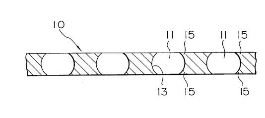
Fig. 1 is an enlarged sectional side view of an
essential part of a liquid filling nozzle plate 10 according
220a~4~
to one embodiment of the present invention, which is set
forth in claim 1. As shown in the figure, through-holes 11
in the liquid filling nozzle plate 10 are each provided with
circumferential projections 15 at the upper and lower ends
of the inner peripheral surface 13 thereof such that the
projections 15 project in a direction in which the inner
diameters of the through-holes 11 are reduced.
It should be noted that these projections 15 describe
approximately circular arcs as seen in a sectional side
view, and thus the inner surface of each through-hole 11
defines a configuration approximately similar to a sphere
with its upper and lower ends cut parallel to each other.
It has been confirmed by an experiment carried out by
the inventor of this application that dripping of liquid can
be prevented more reliably than in the prior art by forming
the through-holes 11 as described above. The reason for
this may be considered as follows:
In this embodiment, as shown in Fig. 2(a), a liquid
filling the space above the liquid filling nozzle plate 10
also fills each through-hole 11. However, the liquid is
kept from dropping from the through-hole 11 by the surface
tension in a state where the liquid surface projects
downward in an approximately circular arc shape from the
underside of the through-hole 11.
In the case of the liquid filling nozzle plate 80
according to the prior art also, as shown in Fig. 2(b), the
liquid filling each through-hole 83 is kept from dropping by
the surface tension in a state where the liquid surface
~ 2 0 3 8 4 u
projects downward in an approximately circular arc shape
from the underside of the through-hole 83.
In comparison of the two nozzle plates, the through-
hole 11 in this embodiment is provided at its lower end with
a projection 15, which projects inwardly. The projection 15
extends in a direction which is approximately coincident
with the circular arc defined by the liquid surface
projecting in an approximately circular arc shape from the
underside of the through-hole 11. In other words, the
direction in which the projection 15 of the through-hole 11
projects approximately coincides with the direction of the
surface tension in which the liquid surface tends to form a
circular arc shape. Consequently, the liquid can be
effectively held at the lower end of the through-hole 11.
In the prior art, on the other hand, the whole inner
peripheral surface of the through-hole 83 extends straight
in the vertical direction. Therefore, the circular arc
defined by the liquid surface projecting in an approximately
circular arc shape at the lower end of the through-hole 83
is not at all coincident with the shape of the lower end
portion of the through-hole 83. Accordingly, force that
holds the liquid at the lower end of the through-hole 83 is
smaller than in the case of the above-described embodiment
of this application.
Incidentally, the liquid filling nozzle plate 10
according to this embodiment is produced by etching or
machining a corrosion-resistant metal sheet.
Next, Fig. 3 is an enlarged sectional side view of an
2~ G084U
g
essential part of a liquid filling nozzle plate 20 according
to another embodiment. As shown in the figure, in this
embodiment an inwardly projecting circumferential projection
23 is also provided at the center of each through-hole 21 in
addition to those provided at the upper and lower ends of
the through-hole 21. With this arrangement, force that acts
to hold the liquid also acts at the central projection 23,
and at the same time, the length of the through-hole 21
increases. Therefore, the surface tension acts even more
effectively to hold the liquid.
Fig. 4 is a view showing one example of a method of
producing the liquid filling nozzle plate 20. As shown in
the figure, the liquid filling nozzle plate 20 is produced
by coating a mask material 27 on both sides of a corrosion-
resistant metal plate 25. At this time, those portions ofthe metal plate 25 which are to become upper and lower
openings of the through-holes 21 are left as circular
portions 28 not coated with the mask material. When the
metal plate 25 is dipped in an etching solution, the metal
plate 25 is etched from the surfaces of the portions 28 as
shown by the dotted lines. Thus, a liquid filling nozzle
plate 20 such as that shown in Fig. 3 can be produced.
However, the etching rate changes with the
concentration of the etching solution, etc. Consequently,
the resulting through-holes 21 do not always have a
configuration such as that shown in Fig. 3. It is therefore
necessary to select an etching material and other
conditions.
2200840
--1 o--
It should be noted that the liquid filling nozzle plate
20 may also be produced as shown in Fig. 5. That is, two
liquid filling nozzle plates 10 as shown in Fig. 1 are
prepared, and the two nozzle plates 10 are laid one on top
of the other and fixed together as one unit.
Next, Fig. 6 is an enlarged sectional side view showing
an essential part of a liquid filling nozzle plate 30
according to still another embodiment. In this embodiment
also, projections 35 are provided at the upper and lower
ends of each through-hole 31 as in the case of the above-
described embodiment shown in Fig. 1. However, this
embodiment differs from the embodiment shown in Fig. 1 in
that each through-hole 31 has an inner surface configuration
defined by two frustums of right-circular cones joined
together at their bases.
With the through-holes 31 formed as described above
also, dripping of liquid can be prevented more reliably than
in the prior art for the same reason stated above in
connection with the embodiment shown in Fig. 1.
Next, Fig. 7 is an enlarged sectional side view showing
a liquid filling nozzle plate 40 according to a further
embodiment. This embodiment is produced by laying two
liquid filling nozzle plates 30 as shown in Fig. 6 one on
top of the other and fixing them together as one unit. With
this arrangement, force that acts to hold the liquid also
acts at the central projection 45 in each through-hole 41,
and at the same time, the length of the through-hole 41
increases. Therefore, dripping of liquid can be prevented
2200840
even more effectively.
Next, Figs. 8(a), 8(b), 8(c) and 8(d) are enlarged
sectional side views respectively showing the structures of
through-holes in liquid filling nozzle plates according to
still further embodiments.
More specifically, as shown in Figs. 8(a) and 8(b),
each through-hole in a liquid filling nozzle plate may be
provided with a projection 46 or 47 only at the lower end
thereof. Alternatively, as shown in Figs. 8(c) and 8(d),
each through-hole may be provided with a projection 48 or 49
only at the center thereof.
Although in the above-described embodiments the
through-holes have a circular configuration (as seen from
above the liquid filling nozzle plate), it should be noted
that the present invention is not necessarily limited to the
circular configuration, and that the through-holes may have
other configurations, e.g. a square, rectangular, elliptical
or polygonal configuration, as a matter of course.
Fig. 9 is an enlarged plan view of an essential part of
a liquid filling nozzle plate 50 according to one embodiment
of the present invention, which is set forth in claim 6. As
shown in the figure, through-holes 51 provided in the liquid
filling nozzle plate 50 have an elongated slit-like shape.
It has been confirmed by an experiment carried out by
the inventor of this application that dripping of liquid can
be prevented more reliably than in the prior art by forming
the through-holes 51 as described above. The reason for
this may be considered as follows:
~2~ 0084u
-12-
In the through-holes 51 according to this embodiment,
two longitudinal opposite sides 53 are close to each other;
therefore, the surface tension increases correspondingly,
and thus dripping of liquid is prevented more effectively
than in the case of through-holes of the same area which
have other shapes (circular or square shape). As the two
sides 53 are brought closer to each other, the surface
tension increases, as will be understood from the phenomenon
that, when the lower ends of two parallel flat plates
disposed close to each other are immersed in a water tank,
for example, the height of a water column pulled up in the
space defined between the two flat plates by the capillary
action increases as the spacing between the two flat plates
decreases.
It should be noted that the opening ratio F of the
liquid filling nozzle plate 50 according to this embodiment
is preferably in the range of from 65% to 35%, more
preferably in the range of from 67% to 43%. The expression
of the opening ratio F is shown below:
F=~(2WLl-0.43W)/SL2}X100(%)
where W : the width (at the shorter side) of the
through-holes 51
Ll: the width (at the longer side) of the
through-holes 51
L2: the pitch between the through-holes 51 in
a direction parallel to the longer side
220084u
S : the pitch between the through-holes 51 in
a direction parallel to the shorter side
Industrial Applicability:
As has been described above, the liquid filling nozzle
plate according to the present invention is used being
attached to the lower end opening of a liquid filling tube
of a liquid filling apparatus. The liquid filling nozzle
plate effectively prevents dripping of liquid from the
liquid filling tube.