Sélection de la langue

Search

Sommaire du brevet 2200920 

Énoncé de désistement de responsabilité concernant l'information provenant de tiers

Une partie des informations de ce site Web a été fournie par des sources externes. Le gouvernement du Canada n'assume aucune responsabilité concernant la précision, l'actualité ou la fiabilité des informations fournies par les sources externes. Les utilisateurs qui désirent employer cette information devraient consulter directement la source des informations. Le contenu fourni par les sources externes n'est pas assujetti aux exigences sur les langues officielles, la protection des renseignements personnels et l'accessibilité.

Disponibilité de l'Abrégé et des Revendications

L'apparition de différences dans le texte et l'image des Revendications et de l'Abrégé dépend du moment auquel le document est publié. Les textes des Revendications et de l'Abrégé sont affichés :

  • lorsque la demande peut être examinée par le public;
  • lorsque le brevet est émis (délivrance).
(12) Brevet: (11) CA 2200920
(54) Titre français: CHAMBRE DE REACTION POUR LE TRAITEMENT DE L'EAU DANS UN SYSTEME DE DEFERRISATION
(54) Titre anglais: REACTOR APPARATUS FOR TREATING WATER IN IRON REMOVAL SYSTEM
Statut: Périmé
Données bibliographiques
(51) Classification internationale des brevets (CIB):
  • C02F 1/74 (2006.01)
  • C02F 1/58 (2006.01)
  • C02F 1/64 (2006.01)
(72) Inventeurs :
  • SCHLAFER, JOHN L. (Etats-Unis d'Amérique)
  • NYLAND, LORI (Etats-Unis d'Amérique)
  • RAATZ, WILLIAM (Etats-Unis d'Amérique)
(73) Titulaires :
  • ECOWATER SYSTEMS, INC. (Etats-Unis d'Amérique)
(71) Demandeurs :
  • ECOWATER SYSTEMS, INC. (Etats-Unis d'Amérique)
(74) Agent: BLAKE, CASSELS & GRAYDON LLP
(74) Co-agent:
(45) Délivré: 2005-06-28
(22) Date de dépôt: 1997-03-25
(41) Mise à la disponibilité du public: 1997-09-29
Requête d'examen: 2001-11-09
Licence disponible: S.O.
(25) Langue des documents déposés: Anglais

Traité de coopération en matière de brevets (PCT): Non

(30) Données de priorité de la demande:
Numéro de la demande Pays / territoire Date
08/625,659 Etats-Unis d'Amérique 1996-03-29

Abrégés

Abrégé français

Système permettant d'extraire le fer de l'eau de puits qui, en plus de sources d'air et d'eau et d'un filtre à matières ferreuses, comporte une chambre de réaction dans laquelle l'eau contenant du fer dissous est mélangée par turbulences avec de l'air et après oxydation de l'eau, l'air en excès est évacué par un moyen de ventilation situé approximativement à mi-chemin entre les extrémités de la chambre de réaction.


Abrégé anglais

A system for removing iron from well water which, in addition to sources of air and water and an iron filter, has a reaction chamber wherein water containing dissolved iron is turbulently mixed with air and after oxidation of the water, excess air is removed through venting means located approximately midway between the ends of the reaction chamber.

Revendications

Note : Les revendications sont présentées dans la langue officielle dans laquelle elles ont été soumises.


What is claimed is:


1. An oxygen/water reactor apparatus for use in a system for removing
dissolved iron from
water, which system includes separate sources of air and water and a filter
for removing iron
oxide from water, the reactor apparatus comprising:

A. a vessel defining a reaction chamber comprising first and second sections,
the
vessel having (1) an inlet connectable to a source of air and to a source of
water and (2) an
outlet connectable to the iron filter for removing iron oxide from water;

B. first baffle means disposed in the first section of the reaction chamber
for
dissolving oxygen in the water to oxidize dissolved iron in the water;

C. second baffle means disposed in the second section of the reaction chamber
for
removing excess gases from the water, whereby water suitable for residential
use is provided,
wherein said first and second baffle means comprise unsupported individual
bodies; and

D. air vent means operably connected to the second section of the reaction
chamber
to vent excess air from the second section of the reaction chamber.


2. An oxygen/water reactor apparatus as defined in claim 1 wherein the first
and second
baffle means comprise spheres that substantially fill the reaction chamber.

3. An oxygen/water reactor is defined in claim 2 wherein each of the spheres
is perforated
and has a diameter of about one inch.

4. An oxygen/water reactor apparatus as defined in claim 2 wherein the spheres
are
constructed of a plastic selected from the group consisting of polyethylene
and polypropylene.

5. An oxygen/water reactor apparatus as defined in claim 1 wherein the vessel
defining the
reaction chamber is comprised of
(a) a substantially vertically disposed elongated body having upper and lower
ends
containing the inlet and outlet, respectively; and


6


(b) the air vent is located between the upper and lower ends.

6. An oxygen/water reactor apparatus as defined in claim 5 wherein the vent is
located
approximately midway between the upper and lower ends of the elongated body.

7. An oxygen/water apparatus as defined in claim 1 wherein the air vent means
include a
one way valve that is normally open but which closes to preclude flow of water
therethrough.

8. In a system for removing dissolved iron from water, which system includes
separate
sources of pressurized water and air and a filter for removing iron oxide from
the water, the
combination of an oxygen/water reactor apparatus comprising:
A. a vessel defining a reaction chamber comprising first and second sections,
the
vessel having (1) an inlet operably connected to a source of pressurized air;
and (2) an outlet
operably connected to the iron filter for removing iron oxide from the water;
B. first baffle means disposed in the first section of the reaction chamber
for
dissolving oxygen in the water to oxidize dissolved iron in the water;
C. second baffle means disposed in the second section of the reaction chamber
for
removing excess gases from the wager, whereby water suitable for residential
use is provided,
wherein said first and second baffle means comprise unsupported individual
bodies; and
D. an air vent means connected to the reaction chamber to remove excess air
from
the second section of the reaction chamber.

9. A system as defined in claim 8 wherein the first and second baffle means
are individual
spheres which substantially fill the chamber.

10. A system as defined in claim 8 wherein the reaction chamber is comprised
of (a) a
substantially vertically disposed elongated body having upper and lower ends
containing the inlet
and outlet respectively and (b) the air vent means is located approximately
midway between the
upper and lower ends.


7


11. A system of removing iron from water comprising:
A. separate sources of pressurized air and pressurized water;
B. an iron filter for removing oxidized iron from the water;
C. an iron oxygen reactor apparatus, having first and second sections,
operably
connected to the sources of water and air and to the iron filter;
D. first baffle means disposed in the first section of the reactor apparatus
for
dissolving oxygen in the water to oxidize dissolved iron in the water;
E. second baffle means disposed in the second section of the reactor apparatus
for
removing excess gases from the water, whereby water suitable for residential
use is provided,
wherein said first and second baffle means comprise unsupported individual
bodies; and
F. a vent operably connected to the second section of the reactor apparatus to
remove excess air from the reaction chamber.


8

Description

Note : Les descriptions sont présentées dans la langue officielle dans laquelle elles ont été soumises.


22 00 ~0
REACTOR APPARATUS FOR TREATING
WATER IN IRON REMOVAL SYSTEM
Technical Field
The present invention relates to a system for removing certain contaminants or
impurities
from well water by oxidation effected by the injection of air into a reaction
chamber having first
and second sections wherein the air is first mixed intimately with incoming
water through the use
of baffles that break up the fluid flow paths and where, thereafter, in the
second section of the
reaction chamber, the baffles act to strip the previously aerated water of
excess air and permit it
1 o to be vented, so that it does not enter the water distribution system.
Background Art
It is well known that water drawn from wells usually contains a variety of
impurities or
contaminants. The most usual contaminants occurring naturally in well water
are iron, sulfur and
manganese, although many man-made contaminants are now also found. These
mineral
contaminants may cause stained plumbing fixtures and corroded pipes and in
addition, may
result in the presence of disagreeable odors and improper taste to the water.
Undesirable mineral content is removed from raw water by a variety of methods,
although most of the methods involve treatment of the water with oxidizing
substances. For
2o example, removal of iron and manganese is commonly effected by running the
water through a
filter with a bed of minerals periodically regenerated with a chemical such as
potassium
permanganate to oxidize the dissolve metals forming either oxides or hydrates
which are
precipitated and removed in the filter. Another method that is widely used is
that of injecting a
quantity of oxygen, either as pure oxygen or more commonly in the form of air.
Possibly the
most widely accepted method for introducing air into well water is by means of
air aspiration
produced through use of a venturi orifice. Of a somewhat more limited use has
been the direct
injection of air under pressure into a body of water to provide the oxygen
necessary to oxidize
the metal ions for ultimate removal from the water.


2~ 00 ~0
A system illustrating the use of air aspiration to precipitate iron is shown
in U.S. Patent
No. 5,096,580. In this arrangement, well water is drawn by means of a pump
through the pipe
102 and into pressure tank 110. From that point, the water ultimately is
directed, upon a demand
basis to oxygen induction device 114, which is in fact a venturi jet that
aspirates air into the
water at that point. The induction of air created by the venturi orifice is
located close to the filter
tank 126 so that build up of precipitated iron oxide or iron hydrates is
prevented from occurring
in pipe 112.
In U.S. Patent No. 3,649,532, water enters through inlet 1 and is passed
through a venturi
type air aspirator unit 2 where it then continues to flow through valve 3 and
to inlet tube 4 which
t o is located on the interior of filter tank 7. An automatic air release 10
is provided in the upper
portion of tank 7 to vent air and sulfur containing gases to the exterior. One
problem
encountered with this type of system results from the fact that the incoming
air/water mixture are
present together for a comparatively short time before being released into the
interior of tank 7
and oxidation of the dissolved metal content is often inadequate to effect
good cleansing of the
well water.
A different sort of system is shown in U.S. Patent No. 4,749,493. In this
instance, an
oxygen supply 74 is introduced into the bottom of a column which contains a
plurality of rings
38. The interior 26 of the column 10 is first filled with an oxygen supply and
then water flows
upwardly through tube 28, exiting through screen 48. The water then percolates
downwardly
2o through the rings 38 acquiring oxygen from the oxygen-enriched environment
that had been
initially placed in column 10 from oxygen supply 74. In this apparatus, the
oxygenated water is
withdrawn through the discharge ports 68 located in the bottom portion of
column 10. U.S.
Patent No. 4,695,378 shows an apparatus used for the purpose of treating acid
mine water and
involves the use of a pair of jet pumps using a venturi effect to provide
aeration of the water.
Following introduction of water through aspiration, the flow is then into a
static mixer 12 which
has a helical interior 12 that swirls the water and air to provide some
additional mixing of the air
and water. This aspiration describes a process for introducing air into acid
mine water and
performing a mechanical mixing operation but does not deal with the ultimate
use of water for
-2-


22 p0 X20
.~ consumer use. Other patents which may be referred to are U.S. Patent Nos.
3,649,533,
4,534,867, 4,659,463, 5,061,377, 5,096,596 and 5,147,530.
Technical Problem To Be Solved
While the processes that constitute the prior art recognize the use of air or
oxygen
introduction into water, for certain purifications, problems still exist. For
example with systems
utilizing venturi aspiration of air into water, the venturi devices are both
difficult to maintain and
to obtain the introduction of sufficient quantities of air into the water to
effect complete oxidation
of dissolved mineral elements. The venturi is a flow restrictor which limits
water pressure to the
1 o end user or adds a load on the well pump. When oxidation does occur,
depending upon the
location where the air is aspirated, precipitation of mineral elements from
solution can occur
which can result in blockage and constriction of conveying pipes. No effective
system is known
in which sufficient oxidation is obtained by merely tumbling air and water
together. In systems
using air injection, un-removed excess air creates blockages and noises in
plumbing systems.
The apparatus of the present invention provides an efficient, economical
apparatus and
system for dissolving substantial quantities of air (oxygen) into well water
and also for removing
excess oxygen that might otherwise result in transport difficulties. In
addition, the present
system ensures that there is maximum physical interaction between the oxygen
bearing air and
the water so that thorough aeration of the water is accomplished to oxidize
the maximum amount
of dissolved mineral content. The apparatus further provides for continued
agitation of the
air/water mixture to result in the removal of excess air and to thereafter
enable its venting to the
exterior of the aerating reactor apparatus. Specifically, by providing a vent
in an air/water
reactor chamber at such a location that excess amounts of air can be present
in a first section of
the chamber while exhausting the excess air from a second section of the
chamber.
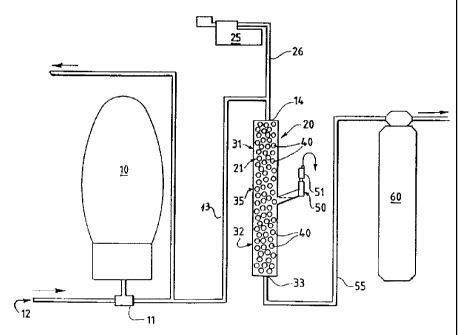
Description of the Drawing
The drawing shows a schematic layout of a mineral reduction system utilizing
the iron
reactor apparatus of this invention.
-3-


22 00 ~o
Description of the Invention
Generally, air injection into well water containing dissolved iron, manganese
and
hydrogen sulfide is a method suitable for treating these contaminants if
certain criteria are met.
Specifically, the system should be maintained at a pH above 6.8, the air and
water must be
adequately mixed for a sufficient amount of time to oxidize the mineral
content and the water
containing the precipitants must then be filtered through a medium, such as
BIRMTM to remove
the particulate material.
Detailed Description of the Preferred Embodiment
to Generally, the principle components of the present system include a
pressure tank 10
which is connected through pressure switch 11 to a source 12, such as a well
pump. The pressure
tank is used to accumulate water taken from the well and stored until it is
needed for use.
Pressure tank 10 is connected, as by means of pipe 13, to an inlet 14 located
in the top of a vessel
20 which defines a reaction chamber 21. Also connected to inlet 14 is a source
of pressurized air
15 25 which provides the air for introduction into the reaction chamber 21,
through pipe 26.
It can be seen by referring to the drawing that the reactor apparatus 20 is
made up of a
substantially vertically disposed elongated body having an upper end 31 and a
lower end 32, the
lower end 32 having an outlet 33. The pre-selected length of the intermediate
portion 35 of
reactor vessel 20 is located about midway between the upper and lower ends 31,
32 of reaction
2o chamber 20.
Contained within the reaction chamber 31 are fluid flow baffles 40 which are
distributed
as unsupported individual bodies substantially throughout the entire volume of
the reaction
chamber. These baffles conveniently take the form of perforated or hollow
balls or spheres
which are about one inch in diameter. The baffle elements are present to
ensure that two
25 individual reactions take place within the reaction chamber. First, when
the water is introduced
into the upper section 31 of reaction chamber 20, it must flow over the
surfaces of the baffle
elements 40; thereby the water is exposed to the maximum effect of the air
already present in the
reaction chamber. As the water flows downwardly through the chamber 21 and
into the lower
section 32, the baffles then continue to turbulently mix air and water, but
simultaneously separate
-4-


22 00 ~~Q
the air from the water, the separated air migrating upwardly toward the air
vent 50. Air vent 50
contains a valve 51 which permits release of the separated excess air from the
second region
within the reaction chamber 21. The water then passes out of the reaction
chamber through
outlet 33 and, via pipe 55, goes into the iron filter 60. The iron filter 60
may contain a substance
such as BIRMTM to further oxidize any remaining solute mineral as well as to
filter out those that
have precipitated from solution.
The iron reactor is intended to be used in a residential household with a well-
pump
system. The iron reactor operates in conjunction with the well pump system
which provides
pressure to the household plumbing. A typical well pump cycle begins when the
well pump
1 o turns on at the lower pressure limit and stays on until enough water has
been introduced to
pressurize tank 10 for the upper pressure limit to be reached and the pump
then turns off. The air
pump 25 of the iron reactor system is wired directly to the same pressure
sensitive switch 11
used by the well pump. When the well pump turns on, the air pump 25 also turns
on. The air
pump at this time delivering air to the reaction chamber 31 while water is
being delivered to
pressure tank 10. After well pump turns off, the air pump 25 also turns off
but the reaction
chamber is now charged with a fresh quantity of oxygen rich air. Subsequently
as water is called
for, it enters the upper section 31 of the iron reactor where the aeration
baffles 32 first mix the air
and water together and then it goes into lower section 32 for separation of
the excess air from the
water.
2o Although the invention has been described with reference to certain
specific
embodiments, various modifications thereof will be apparent to those skilled
in the art without
departing from the spirit and scope of the invention as outlined in the claims
appended hereto.
-S-

Dessin représentatif
Une figure unique qui représente un dessin illustrant l'invention.
États administratifs

Pour une meilleure compréhension de l'état de la demande ou brevet qui figure sur cette page, la rubrique Mise en garde , et les descriptions de Brevet , États administratifs , Taxes périodiques et Historique des paiements devraient être consultées.

États administratifs

Titre Date
Date de délivrance prévu 2005-06-28
(22) Dépôt 1997-03-25
(41) Mise à la disponibilité du public 1997-09-29
Requête d'examen 2001-11-09
(45) Délivré 2005-06-28
Expiré 2017-03-27

Historique d'abandonnement

Il n'y a pas d'historique d'abandonnement

Historique des paiements

Type de taxes Anniversaire Échéance Montant payé Date payée
Enregistrement de documents 100,00 $ 1997-03-25
Le dépôt d'une demande de brevet 300,00 $ 1997-03-25
Taxe de maintien en état - Demande - nouvelle loi 2 1999-03-25 100,00 $ 1998-11-18
Taxe de maintien en état - Demande - nouvelle loi 3 2000-03-27 100,00 $ 2000-02-29
Taxe de maintien en état - Demande - nouvelle loi 4 2001-03-26 100,00 $ 2000-10-31
Requête d'examen 400,00 $ 2001-11-09
Taxe de maintien en état - Demande - nouvelle loi 5 2002-03-25 150,00 $ 2001-11-14
Taxe de maintien en état - Demande - nouvelle loi 6 2003-03-25 150,00 $ 2003-01-10
Taxe de maintien en état - Demande - nouvelle loi 7 2004-03-25 150,00 $ 2003-12-11
Taxe de maintien en état - Demande - nouvelle loi 8 2005-03-25 200,00 $ 2005-02-23
Taxe finale 300,00 $ 2005-04-14
Taxe de maintien en état - brevet - nouvelle loi 9 2006-03-27 200,00 $ 2005-12-05
Taxe de maintien en état - brevet - nouvelle loi 10 2007-03-26 250,00 $ 2007-01-31
Taxe de maintien en état - brevet - nouvelle loi 11 2008-03-25 250,00 $ 2008-01-25
Taxe de maintien en état - brevet - nouvelle loi 12 2009-03-25 250,00 $ 2009-03-02
Taxe de maintien en état - brevet - nouvelle loi 13 2010-03-25 250,00 $ 2010-03-02
Taxe de maintien en état - brevet - nouvelle loi 14 2011-03-25 250,00 $ 2011-03-01
Taxe de maintien en état - brevet - nouvelle loi 15 2012-03-26 450,00 $ 2012-02-29
Taxe de maintien en état - brevet - nouvelle loi 16 2013-03-25 450,00 $ 2013-03-01
Taxe de maintien en état - brevet - nouvelle loi 17 2014-03-25 450,00 $ 2014-03-24
Taxe de maintien en état - brevet - nouvelle loi 18 2015-03-25 450,00 $ 2015-03-17
Taxe de maintien en état - brevet - nouvelle loi 19 2016-03-29 450,00 $ 2016-03-21
Titulaires au dossier

Les titulaires actuels et antérieures au dossier sont affichés en ordre alphabétique.

Titulaires actuels au dossier
ECOWATER SYSTEMS, INC.
Titulaires antérieures au dossier
NYLAND, LORI
RAATZ, WILLIAM
SCHLAFER, JOHN L.
Les propriétaires antérieurs qui ne figurent pas dans la liste des « Propriétaires au dossier » apparaîtront dans d'autres documents au dossier.
Documents

Pour visionner les fichiers sélectionnés, entrer le code reCAPTCHA :


Pour visualiser une image, cliquer sur un lien dans la colonne description du document. Pour télécharger l'image (les images), cliquer l'une ou plusieurs cases à cocher dans la première colonne et ensuite cliquer sur le bouton "Télécharger sélection en format PDF (archive Zip)" ou le bouton "Télécharger sélection (en un fichier PDF fusionné)".

Liste des documents de brevet publiés et non publiés sur la BDBC .

Si vous avez des difficultés à accéder au contenu, veuillez communiquer avec le Centre de services à la clientèle au 1-866-997-1936, ou envoyer un courriel au Centre de service à la clientèle de l'OPIC.


Description du
Document 
Date
(yyyy-mm-dd) 
Nombre de pages   Taille de l'image (Ko) 
Dessins représentatifs 1997-11-06 1 6
Page couverture 1997-11-06 1 36
Abrégé 1997-03-25 1 13
Description 1997-03-25 5 256
Revendications 1997-03-25 3 100
Dessins 1997-03-25 1 15
Revendications 2001-11-09 3 107
Dessins représentatifs 2005-06-01 1 9
Page couverture 2005-06-01 1 34
Cession 1997-03-25 7 226
Poursuite-Amendment 2001-11-09 4 140
Poursuite-Amendment 2001-11-09 1 40
Correspondance 2005-03-02 1 16
Correspondance 2005-03-02 1 19
Taxes 2003-12-11 1 25
Taxes 1998-11-18 1 38
Taxes 2000-02-29 1 30
Correspondance 2005-02-23 2 42
Taxes 2005-02-23 1 35
Correspondance 2005-04-14 1 27
Taxes 2007-01-31 1 29
Taxes 2005-12-05 1 25
Taxes 2008-01-25 1 28
Taxes 2015-03-17 1 38