Note : Les descriptions sont présentées dans la langue officielle dans laquelle elles ont été soumises.
CA 02202073 1997-04-07
W O96/11106 PCTrUS95/13326
Description
FLOOR MAT AND CONTINUOUS PROC~ESS FOR TUE
MANUFACTURE Tl~li.REOF
Techniçal Field
The present invention relates generally to launderable rubber backed floor mats
of the type which have a pile surface on one side and a rubber or rubber-like m~t~ri~l on
the other side and a continuous process for producing the same. More particularly, the
invention relates to the continuous production of floor mats involving the extrusion of a
vulcanized thermoplastic elastomer as a backing material for a tufted fabric composite.
Background Art
Dust control mats and other floor coverings having a pile side and a rubber
backing are generally used in access ways where people tend to brush or scrape their
feet in order to prevent carrying moisture and/or dirt into other areas of the premises.
Normally these mats are located in areas of high pedestria:n traffic such as doorways.
The art incllldes a number of configurl~tions and features for various floor mats.
Some patents which are believed to be illustrative of known floor coverings include
U. S. patents 3,306,808 to Thompson, et al. issued Febrwary 28, 1967; 4,741,065 to
Parkins issued May 3, 1988; 4,886,692 to Kerr et al. issued December 12, 1989;
5,227,214 to Kerr et al. issued July 13, 1993; 5,240,530 to Fink issued August 31,
1993; and 5,305,565 to N~g~h~rn~ et al. issued April 26, 1994; the te~.hing of all of
which are incorporated herein by reference.
.
CA 02202073 1997-04-07
W O 96/11106 PC~r~US95/13326
As will be appreciated by those of skill in the art, fioor mats have conventionally
con~i~ted of a plurality of tufts in a primary backing adhered to a vulcanized thermoset
rubber backing. Such a bac~in~: gives rlimen~ nal stability to the fabric surface while
m~ the mat's integrity during intlll~tri~l wash processing. Heretofore, the
5 production of launderable fioor mats has relied on the use of thermoset rubber backing.c
based on nitrile polymer formulas. While such mats perform very adequately, the
m~mlf~chlrer of such mats has historically been presented with certain limitations due to
the formation of the mats as modular units as opposed to the continuous production
made possible by the present invention.
Mats formed using thermoset rubber backing.c require the stationary
co~ ression and applicatic)n of sufficient heat and pressure to vulcanize the rubber
backing and adhere it to the fabric. Such batch operations are limited by the curing rate
characteristics of the thermoset rubber. Additionally, the process has historically
involved cutting the thermoset rubber to length, po~itit~nin~ the rubber backing on a
5 carrier belt or conv~;yor and thereafter laying the tufted fabric onto the rubber backing
and fusing the components together. Once vlllc~ni7erl any excess rubber not necessary
for the finished specified dimPn~icns of a thermoset mat is cut away and discarded rather
than being easily recycled as in the present invention. The use of a process which can
deposit an appropliate backing m~tP.ri~l onto a fabric substrate in a continuous manner
2 0 thereby producing a mat m~tP.ri~l which can be cut to given dimensions therefore
represents a useful adv~ncement over the art.
CA 02202073 1997-04-07
W O96/11106 PCT~US95113326
Disclosure of Invention
In light of the foregoing, it is a general object of the present invention to provide
a mat formed by the continuous disposition of a vulcanized thermoplastic elastomer
onto a tufted fabric substrate.
It is a related object of the present invention to provide a process for depositing
vulcanized thermoplastic el~.~tomer onto a fabric substrate to achieve a desirable mat
configuration.
Accordingly, it is a feature of the present invention to provide a continuous mat
forming process wherein layers of adhesive and backing m~t~.ri~l~ are deposited in a
continuous fashion as layers across a tufted fabric composite.
In one aspect of the present invention a novel dust control mat is provided
compri~ing a plurality of tufts in a primary base. A layer of thermoplastic adhesive is
used to adjoin the plilll~y base to a vlllc~ni~ed thermoplastic elastomer backing which
has been deposited continuously across the adhesive backed fabric. The thickness of the
vlllc~ni7ed thermoplastic ~ tomer layer is between about 20 mils and about 40 mils
and preferably in the range of about 30 mils. In the pl ~r~ll ed practice of the present
invention, a stabilizing layer of woven or nollwovell thermoplastic scrim or film will be
deposited on the underside of the thermoplastic elastomer backing and a second layer of
vulcanized thermoplastic el~tomer will be deposited across the scrim in a sealing
2 o manner. The thickness of this second layer of vulcanized thermoplastic elastomer will
be in the range of about 20 and 40 mils and preferably about 30 mils.
CA 02202073 1997-04-07
WO 96/11106 PCT/US95113326
Brief Description of The Dl ~wings
Figure 1 is a s~.hem~tic representation of a mat forming process according to the
present invention.
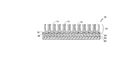
Figure 2 is a cross-section ofthe potentially plerelled mat ofthe present
invention as formed by the process illustrated in Figure 1.
W~hile the invention has been illustrated and will be described in connection with
certain plert;ll~d embodiments and practices, it is to be understood that it is not
intP.ncled to in any way limit the invention to such embodiments and practices. On the
contrary, it is intPn~1ed to cover all ~ltprn~tives~ modifications and equivalents as may be
inclllded within the spirit and scope of the invention as limited and defined b~ the
appended claims.
Best Mode For Car~ing Out The Invention
Turning now to the drawings, in Figure 1 there is shown a process line for the
production of a mat according to the present invention. As shown, a primary fabric 10
is withdrawn from a supply roll 12 for application of various substrate layers. The
primary fabric 10 preferably incllldes a plurality of pile yarns 14 of cotton, nylon,
polyester or other suitable m~tPri~l tufted through a woven or noIlwl~ven carrier layer
16. In the pl~r~lled embodiment, the carrier layer 16 is a nonwoven layer of
poly~ro~ylene.
2 o In practice, the primary fabric 10 is ~ srelled from the supply roll 12 to a first
heating unit 20 for application of preheat so as to raise the temperature of the primary
fabric to a level of between about 220F to about 260F. A first extruder 22 is
-
CA 02202073 1997-04-07
W O 96/11106 PCTrUS95/13326
thereafter used to deposit a layer of adhesive 24 across the surface of the carrier layer
16 from which the tufts of yarn do not extend. In the pr~relled practice, the first
extruder will be ~it~l~ted to deposit the adhesive 24 on a first nip roll 26 for passage
between the first nip roll and a first casting roll 28. The first nip roll 26 will preferably
5 include means to pull a vacuum at a level of between about 10 and 20 inches of mercury
at the face of the plhllaly fabric as the adhesive 24 is being deposited so as to hllprove
the adherence ofthe adhesive 24 to the back of the carrier layer 16. Since the adhesive
24 is applied at a temperature of between about 320F and 560F, it has been found that
- heating the first casting roll 28 at a level of up to about 200F or more further f~.ilit~tes
10 the adhesive application process.
In the pr~r~lled practice of the present invention, l;he adhesive 24 is applied at a
thickness of between about 4 mils and about 12 mils. The adhesive is preferably an
olefin based adhesive so as to improve adhesion to the vulcanized thermoplastic
elastomer backing applied in later steps. Specifically, one potentially plt;rell~d adhesive
15 is a thermoplastic adhesive resin based on polyethylene which is believed to be available
from Exxon Corporation under the trade design~tion ATX-310. By way of illustration
only, other suitable adhesives may include therrnoplastic adhesive resins based on
poly~lopylene. One such polyl~lupylene based adhesive is believed to be available from
Uniroyal Chemical Col~ally, Inc. under the trade design~tion Polybond~) 2006. Yet
2 o another potential adhesive is a modified ethylene-vinyl acetate co-polymer resin believed
to be available from Quantum Chemical Company in Cincinnati, Ohio under the trade
de~ign~tinn Plexar~) PX5298.
It has been found that the air space between the first extruder 22 and the point of
CA 02202073 1997-04-07
W 096tlllO6 PCTrUS~S/13326
application on the primary fabric lO is extremely important. Specifically, it has been
found that this air space should be no grater than about 4 inches and is preferably in the
range of about l inch or less.
Following application of the layer of adhesive 24 at the first extruder 22, the
5 primary fabric l O with applied adhesive is thereafter conveyed to a second heating unit
30 for heating to a level of between about 220F and 260F. The heated com.posite
structure is thereafter collv~yt;d to a second extruder 32 for application of a first layer of
vulcanized thermoplastic elastomer 36 (Figure 2).
In the pl~r~;lled practice, a layer of polyolefin based reh~l~ g scrim 40 which
lo may be either woven or no~woven material is conveyed to the nip between a second nip
roll 42 and second casting roll 44 to thereby form a layered structure wherein the
vulcanized thermoplastic elastomer is disposed across the previously deposited layer of
adhesive 24 and the scrim is deposited on the backing of the thermoplastic elastomer. It
is, of course, to be understood that the rei.~l~,ing scrim 40 could be ~limin~ted if
15 desired.
As will be appreciated, the joining of m~t~ri~l layers at the nip between the
second nip roll 42 and the second casting roll 44 provides for the application of
significant pressure on the composite m~t~ri~l~ It has been found that the edges of the
mat m~t~ri~l which have no tufts ~ tP.ntling therefrom may tend to be damaged as the
2 o composite m~tP.r;~lc are squeezed through the nip. To alleviate this problem the second
nip roll 42 is preferably formed of a relatively soft rubber having a Shore A hardness of
between about 40 and about 80 and preferably about 50 so as to permit the nip roll 42
to deforrn around the higher profile tufted areas of the mat material thereby tending to
- CA 02202073 1997-04-07
W O96/11106 PCTrUS95/13326
equalize the pressure distribution as the composite is passed through the nip between
the rolls. The nip roll 42 could also be provided with belt structures (not shown) at
either end of the nip roll to help equalize stresses applied across the composite
m~t~ri~l~ The width of these belt structures is subst~nti~lly equivalent to the width of
5 the nontufted boundary edge of the mat m~t~ri~l It has been found that by the
pl~c~.ment of these belt structures at the edges of the nip roll that stresses are more
ul~iro~ ly distributed across the composite fabric structure, thereby subst~nti~lly
red~lcin~ any potential for damage to the nontufted edges.
The layer of vulcanized thermoplastic elastomer (vulcanized TPE) 36 is
10 preferably applied from the second extruder at elevated temperatures of at least about
450F and more preferably 500F or more. The vlllc~ni7ed thermoplastic elastomer
which is utilized is preferably an EPDM based olefinic thermoplastic vlllc~ni7ed
elastomer such as is disclosed and described in U.S. pate~ts 4,130,535 to Coran,
4,311,628 to Abdou-Sabet et al. and 4,594,390 to Abdou-Sabet et al. (all incorporated
15 by reference).
The p~ d vlllc~ni7ed TPE's include cross-linked rubber particles dispersed
through a continuous matrix of thermoplastic m~t~ri~l (i.e. a rubber phase and a plastic
phase). An average rubber particle size of one micron or less is favorable in the
el~.ctomer for use in the present invention. The rubber phase of the vlllc~ni7.ed TPE is
2 0 preferably EPDM but may also be formed from nitrile, butyl, natural or styrene
butadiene rubber polymers. Such vulcanized TPE's are believed to be available from
Advanced Elastomer Systems L.P. in Akron, Ohio under the trade dç~i~n~tinn
Santoprene~.
CA 02202073 1997-04-07
W O 96tlllO6 PCTtUS95/13326
As will be appreciated, the use of such vulcanized TPE's permits the controlled
application of specific tllicknesstq.~ of the polymer. Specifically, the thickness of the
layer of vlllc~ni7ed thermoplastic ~ tomer 36 applied by the second extruder is
preferably greater than 20 mils, and more preferably in the range of between about 20
5 mils and about 40 mils and most preferably about 30 mils.
While the production of the mat may be c~ ncl~1ded after the disposit of the first
layer of vulcanized TPE from the second extruder 32, in the pl~relled practice, the
composite which is formed at the nip between the second nip roll and casting roll 42, 44
is thereafter collvt;yed to a third heating unit 50. The third heating unit 50 preferably
10 heats the composite formed at the second extruder to a level of between about 220F to
about 260F. The heated composite is thereafter preferably passed between a third nip
roll 52 and a third casting roll 54. In the plt;relled practice, the third nip roll 52 is also
either deformable or provided with belt structures as previously described so as to
protect the nontllfted edge m~t~ri~l
As the composite m~tlo.ri~l inc~ ing the layer of vlllc~ni7ed thermoplastic
elastomer 36 and leh~l~ g scrim 40 is passed between the third nip roll 52 and casting
roll 54, a second layer of vlllç~ni7ed TPE 60 is preferably deposited by a third extruder
62. In the pl~rt;;lled practice, the composition and disposition of the second layer of
vlllc~ni7.~d TPE will be substantially similar to that of the first layer. That is, the
2 o temperature of the vlllç~ni7ed TPE will preferably be at least about 450F and most
preferably about 500F or more and the thickness of the resultant layer will be between
about 20 mils and about 40 mils. The resultant final mat structure 70 may thereafter be
transferred to a take-up roll 72 and then cut into sections of apprupliate length for us as
CA 02202073 1997-04-07
WO 96/11106 PCTIUS95/13326
mats.
Accordingly, it can be seen that the present invention provides a continuous
process for the production of mat structures which gives rise to a highly useful and
easily m~mlf~ctllred product. While specific embodiments and practices have been
5 illustrated and described in accordance with the present invention, it is to be understood
that the invention is not limited thereto, since modifications may be made in other
embo(limentq of the princip~l.q will occur to those skilled in the art to which this
invention pertains. Therefore, it is intP.nded to cover any such mo(lificatinns and
~ ~lt~ ;ves as incorporate the features ofthe present invention within the true spirit and
10 scope of the following claims and its equivalent.