Note : Les descriptions sont présentées dans la langue officielle dans laquelle elles ont été soumises.
CA 02202236 1997-04-09
--1--
The instant invention pertains an apparatus for triggering
an avalanche or the like by using an explosive charge,
which is brought into an avalanche slope and which is
detonated therein.
Because of safety reasons in high-alpine areas, especially
in those that are opened up for skiing there exists a
requirement to artificially trigger avalanches in order to
exclude an endangerment of people, especially skiers caused
by uncontrollable starts of avalanches or the like. There
is also the requirement to trigger avalanches in order to
avoid a destruction of housing areas, roads, woods or the
like, which can be caused by the uncontrollable start of
avalanches.
In order to artificially trigger avalanches, it is known to
shoot at avalanche slopes with rockets. This method,
however, has the disadvantage of only securing a low
accuracy in reaching the target because of which colonized
areas could be reached and furthermore only securing low
ignition safety because of which the rate of success is
low. Further disadvantage of rockets are that they are
expensive and that they represent military weapons because
of which the use thereof is subjected to legal and
contractual limits.
It is further also known to set up cable railway facilities
CA 02202236 1997-04-09
in the areas of slopes from which avalanches can start with
which explosive charges can be brought to exactly
determined areas and can there be brought to detonation,.
The set-up as well as the operation of these facilities,
however, are very costly. The operation is costly because
those areas at which the explosive charges are to brought
to detonation have to be determined by measurements during
the delivery process, wherein, for that purpose, operating
personnel has to be present at the facility. The use of
explosive charges is furthermore limited to areas which is
covered by the cable railway facility.
It is also known to manually throw explosive charges into
avalanche slopes. Since, however, the endangerment of the
operating personnel has to be excluded, this method can
only trigger avalanches to a very limited extent. It is
also known to throw explosive charges into avalanche slopes
from helicopters. Besides the fact that this method is also
costly, it requires weather conditions, in which helicopter
flights are possible and admissible. This method,
therefore, is subject to large organizational limits.
The purpose of the instant invention, therefore, is to
create an apparatus with which explosive charges can be
brought into avalanche slopes with a relatively low expense
on the one hand but with a relatively high accuracy on the
CA 02202236 1997-04-09
--3--
other hand in order to artificially trigger the start of
avalanches. It should thereby be possible to cover any
amount of target areas in a simple fashion. It should
further be possible to trigger the avalanches at any given
time and independently of climatic conditions, especially
weather conditions, as well as independently of
accessibility of the area due to weather conditions.
This is attained, according to the invention, in that the
explosive charge is located in a tube which is closed at
one end in which a propelling charge is arranged through
which the explosive charge can be brought from the tube
into the avalanche slope.
The explosive charge is preferably loczted between the
bottom of the tube and the explosive charge. The insertion
of the explosive charge and the propelling charges thereby
takes place through the open end of the tube. As far as the
bottom of the tube is solubly attached to same, the
insertion of the explosive charge and the propelling charge
can also take place from the bottom end of the tube.
Preferably a plate made of stiff metal is located between
the explosive charge and the propelling charge by which the
thrust created by the propelling charge is transferred onto
the explosive charge.
CA 02202236 1997-04-09
Preferably, the explosive charge is located in a tube-like
casing which is closed by caps, wherein the propelling
charge is arranged on the cap which is attached to the
bottom closure of the tube.
According to a further preferred embodiment, the tube has a
lateral slit or the like close to its bottom through which
the propelling charge can be inserted into the tube. A
carrying plate can thereby further be provided, which has a
recess for picking up the propelling charge and which can
be inserted into the tube through the slit. There can
further be provided an intermediate plate or the like which
can be inserted into the tube between the propelling charge
and the bottom of the tube.
According to a further preferred embodiment, there is
provided a fuse which runs into an explosive capsule which
is arranged in the explosive charge. This effects that the
explosive charge is only detonated after it penetrated the
avalanche slope. The lighting mechanism for the fuse is
further preferably connected with a bolt or the like which
is arranged on the tube via a pulling element, wherein the
length of the pulling elements is at least equal to the
axial length of the tube. This guarantees that the
explosive charge is only detonated as soon as it has left
the tube, which safely excludes a damaging or destruction
- CA 02202236 1997-04-09
_5_
of the tube caused by a misfire of the propelling charge.
On the outside of the tube there is further preferably
arranged a terminal for an electric line leading to the
propelling charge. The propelling charge which was inserted
into the tube is connected to this terminal. Via a control
line or via a radio signal the detonation of the propelling
charge can thereby be immediately triggered.
According to a further preferred embodiment there is
provided a carrying device for a multiplicity of tubes for
catapulting explosive charges which is either stationary or
movable. This carrying device is pivotable about an
approximately vertical axis. The tubes can further
adjustably and fastenably arranged in their angular
position on the carrying device. With this measure the
tubes can be adjusted to different target areas, whereby
avalanches can be triggered in different areas by
consecutive detonations of explosive charges.
The object of the invention is explained in the following
in more detail in embodiments shown in the drawing. There
is shown in
Fig. 1 an apparatus according to the invention in axial
section,
CA 02202236 1997-04-09
- --6--
Fig. la a changed embodiment with regard to Fig. 1 of an
apparatus according to the invention, in axial
section,
Fig. lb a further changed embodiment as compared to Fig. 1,
in axial section,
Figs. 2 and 2a a side view and a top view of a set of such
apparatus, which is arranged on a transport sledge,
Figs. 3 and 3a a side view and a top view of a set of
apparatus according to the invention which is arranged
on a stationary carrying device, and
Figs. 4 and 4a a side view and a top view a detail of Figs.
2, 2a and 3, 3a in a ratio which has been enlarged
with respect to these figures.
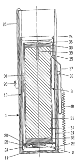
An apparatus according to the invention consists of a tube
1 which is open on one end in which an explosive cartridge
10 is inserted which is attached to the bottom 11 of the
tube 1 and which contains a propelling charge 2 and an
explosive charge 3. The explosive cartridge 10 has a tube-
like casing 21 which is closed at its lower end via a cap
22 and on its upper end via a cap 23. The propelling charge
2 is located in the area of the lower cap 22. A plate 20 is
attached thereto onto which the explosive charge 3 is
attached. The propelling charge 2 further contains a
detonator 24 which is connected to a clamp 26 via an
electrical line 25.
- CA 02202236 1997-04-09
--7--
The explosive charge 3 also consist of a tube-like casing
31, which is closed at both front areas with caps 32 and 33
and which is filled with an explosive 34. A lighting
mechanism 35 is located on the outside of the casing 31
from which a fuse 36 extends which penetrates the closing
cap 33 and which ends in an explosive cartridge 39 which is
arranged in the explosive 34. The lighting mechanism 35 has
a pulling element 37 which is attached at a bolt 38 or the
like which extends out of the casing 1. The pulling element
37 is further attached to a repelling device in the form of
a tension spring 40.
The tube 1 is made of metal, as for example sheet-metal or
aluminum. Contrary to this the plates 20 and the casing 31
of the explosive charge 3 are made of material which will
rot due to weather influences, as for example cardboard,
paper-mâché or a wood solid solution. Such an explosive 34
is located in the casing 31 which is not triggered even
through very low temperatures. On the outside of the casing
31 there if further arranged a reflector 30 which serves to
more easily locate explosive charges 3 which have not been
effective due to misfires.
In the embodiment shown in Fig. la, the explosive cartridge
10a consist of a tube 31, wherein the cap 32 has a recess
CA 02202236 1997-04-09
--8--
32a on the side which is attached to the bottom 11 of the
tube 1 in which the propelling charge 2 is inserted and
held via gluing, for example.
In the embodiment shown in Fig. lb, the case of the tube 1
close to the bottom 11 is arranged with a slit 12 through
which a carrying plate 13 can be laterally pushed into the
tube 1 which forms a receiver for the propelling charge 2.
The line 25 which leads to the connection clap 26 thereby
intersperses a further slit 12a. The plate 13 has a recess
13a on its side which faces the explosive charge 3, into
which the powder material of the propelling charge 2 is
filled. From the recess 13a a duct, in which the line 25 is
led, leads radially outwardly. The recess 13a is closed
with a cover 14.
In order to avoid the leaking of gases through the slits 12
which form when detonating the propelling charge 2, there
is further provided an intermediate plate 15 which is also
inserted underneath the carrying plate 13 through the slit
12, wherein the carrying plate 13 is lifted contrary to the
slit 12 so that gases cannot leak trough it. The handling
of the intermediate plate 15 is carried out via a handle in
the form of a ring 16 which extends therefrom through the
slit 12. In order to more easily insert the intermediate
plate 15 into the tube, a wedge-shaped slope can be
CA 02202236 1997-04-09
provided on the side opposite to the handle 16.
In this embodiment the explosive cartridge 3 and the
propelling charge 2 can be transported independently of
each other wherein they are inserted into the tube 1 when
preparing the apparatus for triggering avalanches.
Different amounts of propelling charges can be used with
different sizes of the recess 13a, whereby different throw
width can be reached. ~lternatively, prefabricated
propelling charges 2 with different sizes can be inserted
into the recess 13a of the carrying plate 13.
Since the carrying plate 13 and the intermediate plate 15
are reusable, they can be manufactured from non-rotting
material, for example also from sheet metal.
The mode of operation of this apparatus is as follows:
Such an apparatus or a set with a multiplicity of such
apparatus is installed at the edge of a slope or inside a
slope in which avalanches are to be triggered. As soon as
an electrical impulse is given via the line 25 to the
detonator 24 of the propelling charge 2, the propelling
charge is detonated whereby the explosive charge 3 is
thrown out of the tube 1 through the thrust created
thereby. As soon as the explosive charge 3 has moved about
CA 02202236 1997-04-09
--10--
a distance which is approximately equal the distance of the
puling element 37, the lighting mechanism 35 is activated
by the pulling element 37, whereby the fuse 36 is lit. As
long as the line 25 is brought along out of the tube 1, it
is pulled out of the clamp 26. With the propelling charge
2, the explosive charge 3 is thrown over distances of for
example 30 to 250 m into a slope in which an avalanche is
to triggered. The explosive charge 3 is detonated as soon
as the explosive cartridge 39 is lit via the fuse 36
whereby an avalanche is triggered because of the pressure
wave created through this.
Since the lighting mechanism 35 is triggered by the pulling
element 37, it is avoided that the explosive charge 3 is
detonated within the tube 1 which would destroy the same
and which would also lead to the detonation of the
explosive charges which are located next to it. The
lighting mechanism 35 is triggered with the pulling element
37 only after the explosive charge 3 has left the tube 1.
Then a delay in detonation of for example 120 seconds is
effected through the fuse 36 which guarantees that the
explosive cartridge 3g is only ignited and that through
this the explosive charge 3 is only brought to detonation
after it has reached the target area.
CA 02202236 1997-04-09
--11--
In the following there is described a mobile device such
apparatus in Figs. 2 and 2a. This device consist of a
sledge 4 on which there is arranged a carrying device 5 for
a set of apparatus 1 according to the invention. The
apparatus 1 are located in a casing 6, which can be closed
with lids 61 and 62. The movement of the lids 61 and 62
takes place with actuators. The apparatus 1 are inserted
into shells 60 which are adjustably and fastenably arranged
opposite the carrying device 5. There is further located a
mounting platform 7 below the casing 6 from which the
casing 6 can be supplied with a multiplicity of apparatus
1.
The apparatus 1 are further enclosed by lids 63, made for
example or plastic foils, in order to prevent a penetration
of moisture through which they could become inoperable.
On the sledge 4 there is further located a mast 52 on which
a solar panel 51 is attached, the exit of which is put on a
battery 54 which is also arranged on the mast 52. A control
box is further arranged on the mast 52 on which the exit of
a hand control device 55 is connected via a line 56. The
control box 53 if further arranged with an antenna 58.
In Figs. 3 and 3a there is further shown such a device
which is arranged stationarily.
- CA 02202236 l997-04-09
--12--
It is obvious from Figs. 4 and 4a that two actuators 6 are
located in the casing 6 through which the lids 61 and 62
are adjustable.
As soon as the explosive charge 3 is to be thrown into an
avalanche slope at least one the lids 61 and 62 is moved in
its open position and the propelling charge 2 is ignited.
In order to reach different target areas, the carrier 5 can
be rotatable by at least an approximately vertical axis.
Furthermore, the shells 60 can be adjustable and fastenable
in their angular position contrary to the carrying device
5. The twisting of the carrying device 5 and the adjustment
of the angular position of the tube 1 can take place
mechanically vi2 a control line or by radio. Furthermore,
different throw widths can be achieved by differently
dimensioned propelling charges 2.
Since the apparatus according to the invention are arranged
in the casing 6 which is lockable by lids 61 and 62, they
are protected against weather influences and unauthorized
manipulations. The adjustment of the lids 61 and 62 can
also be carried out by remote control. The call back device
40 prevents that the pulling elements 37 reach the area of
the lids 61 and 62 after they have been separated from the
lighting mechanism 35, whereby their function could be
- CA 02202236 l997-04-09
--13--
hindered. The energy necessary for operating the device is
provided by the battery 54 which is recharged by the solar
panel 51. Alternatively, this device can be supplied with
energy via electrical lines.
Apparatus according to the invention can, for example, also
be mounted on ski-run devices. The triggering of the
propelling charges 2 can be directly effected on the
carrying device or via a control line. A receiver can
furthermore be provided on the carrying device, whereby a
triggering can also be effected by radio control.
Such stationary or mobile devices can be equipped with 30
tubes 1, into which explosive cartridges 10 or lOa have
been inserted.
The apparatus can either be brought into the alpine area at
the onset of winter whereby they would be at disposal
during the winter or they could also be brought into the
area during the winter. As far as there is a necessity, a
supplementing with explosive cartridges 10 or lOa can be
arranged. Since the tubes 1 are kept in the shells 60, the
explosive cartridges 10 or lOa can be inserted into the
tubes 1 at any location and only the tubes 1 which contain
the explosive cartridges 10 or lOa have to be inserted into
the shells 60. The entire device is ready for operation as
CA 02202236 l997-04-09
--14--
soon as the control lines 25 are connected to the clamps
26.