Note : Les descriptions sont présentées dans la langue officielle dans laquelle elles ont été soumises.
CA 02203025 1997-04-17
WO 97/09479 PCT/CTS96/02493
Method to Reduce
Forming Fabric Ed,~e Curl
Background of the Invention
1. Field of the Invention
The present invention relates to the fabrics used
as forming media in modern papermaking machines. More
particularly, a method for treating a forming fabric
in order to reduce or eliminate the problem of edge
curl is disclosed.
2. Description of the Prior Art
Broadly stated, the purpose of modern papermaking
machines is to remove water from a stock or furnish
consisting of an aqueous suspension of wood fibers and
a variety of other ingredients. Generally, modern
papermachines are made up of three distinct sections.
The first is the forming section, where the
furnish is applied to a moving screen, traditionally
referred to in the industry as a wire. The wire's
screen-like construction enables water to drain
readily from the furnish leaving a web of wet wood
fiber on its upper surface.
At the end of the forming section, enough water
has drained from the wet wood fiber for it to assume
the form of a wet sheet of sufficient structural
integrity to be transferred to a press fabric. The
wet sheet is carried on to the press section either
atop this single press fabric or sandwiched between
two such fabrics. The press fabrics serve the purpose
of removing further amounts of water from the wet
' sheet. Here, however, because the water that remains
will not drain from the sheet on its own accord, the
combination of fabric and wet sheet are passed
CA 02203025 1997-04-17
WO 97/09479 PCT/CTS96/02493
together through a series of presses where water is
squeezed from the sheet and accepted by the fabrics.
At the end of the press section, the wet sheet
proceeds to the final stage of the papermachine, the
dryer section. There, the sheet is conducted or
passed around each in a series of cylinders steam-
heated from within. Whatever water still remains in
the sheet on reaching the dryer section is gradually
driven off by evaporation upon contact with the hot
cylinders. Fabrics are employed in this section as
well. Here, however, they do not so much carry or
conduct the sheet as serve to hold the sheet in
intimate contact with the surface of each cylinder as
an aid to efficient drying.
~.5 The fabrics used in each section take the form of
long, continuous, endless moving belts. They are
either woven in endless form or seamed into that form.
Depending on the papermachine, the belts can be from
1 to l0 meters wide and of considerably longer total
length.
As stated rather implicitly above, the paper
manufacturing operation is continuous. In other
words, furnish is continuously applied to the wire,
forming a wet sheet which is transferred, in turn, to
the press and dryer section, emerging finally as some
form of paper product.
The fabrics used in the forming stage will be our
chief concern here. The forming fabrics, or wires,
play a crucial role in the papermaking process. They
must be highly permeable and allow large quantities of
water to drain quickly from the furnish, and must be
of a weave to assure optimum sheet formation. Of
equal importance, the upper surface of the forming
fabric, to which the furnish is applied, should be as
2
CA 02203025 1997-04-17
WO 97/09479 PCT/LTS96/02493
smooth as possible in order to assure the formation of
a smooth, unmarked sheet.
Formerly, the fabrics used in the forming section
were woven from metal threads. For this reason, they
are still commonly referred to in the papermaking
industry as wires, even though most are now woven from
synthetic monofilament.
A wide variety of these fabrics are in current
use, and can be characterized by weave pattern and
number of layers. One chooses a particular fabric to
meet the requirements of the machine on which it is
to
be installed and the kind of paper to be produced.
Generally, the systems of yarns in a woven fabric
lie in directions which can be identified with
reference to the directions they take when the fabric
a.s in its position of use on the papermachine . The
machine direction yarns lie in the direction in which
the fabric as a whole moves when the machine is
operating and, accordingly, must bear forces of
tension associated with this motion.
Transverse to the machine direction yarns are
cross-machine direction yarns. By contrast, the
cross-machine direction yarns are subjected to very
little, if any, tension on the papermachine.
In some of the weave patterns in current use, the
cross-machine direction yarns pass over more than one
machine direction yarn before weaving under one such
yarn and repeating the pattern. A fabric is thereby
produced having an upper surface formed primarily from
the cross-machine yarns or shutes. Normally, this
side is used for the formation of the paper sheet, and
can be referred to as the long-shute knuckle side.
' An undesired consequence of such weave patterns
is that the forming fabrics so characterized tend to
curl in a direction toward the long-shute knuckle side
3
CA 02203025 2000-02-07
with time as back side wear and/or shrinkage occurs .
The curl arises because these cross-machine weave
patterns result in the shrink forces on each side of
the upper ,surface being unequal. The resulting curl
can cause c>perational problems on the papermachine.
Une prior-art method for reducing forming
fabric edge curl is disclosed in U.S. Patent No.
4,941,239 issued to Fliss on July 17, 1990, which
patent is commonly assigned with the present
invention. The method requires the removal of mass
from the sheet-forming side of the forming fabric.
This has the effect of reducing the ratio between the
shrink forces acting on the two sides of the forming
fabric in the cross-machine direction and, in turn,
reduces the tendency for shrinkage to cause the edges
of the fabric to curl. More specifically, the mass
is removed by using a fine abrasive medium on the
surface of the fabric. While one could remove mass
from the Entire sheet-forming side of the forming
fabric in vhis manner, it is preferable to so treat
only regions lying in a band along each of the two
lateral edges thereof, so as not to adversely affect
its paper-forming characteristics.
The present invention provides another
solution to the problem of forming .fabric edge curl.
Summary of the Invention
The present invention is a method for
reducing firming fabric edge curl which does not
require the removal of mass from the cross-machine
direction yarns on the long-shute knuckle side.
Instead, tree imbalance between the shrinking forces
on the two sides of the forming fabric is reduced in
the practice of the present invention by slitting or
scoring the cross-machine direction yarns on the
4
CA 02203025 2000-02-07
long-shute knuckle side. As with the method shown in
aforementioned U.S. Patent No. 4,941,239, the
slitting or scoring has the effect of reducing the
ratio between t:he shrink forces acting on the two
sides of the forming fabric in the cross-machine
direction, bringing that ratio down closer to unity,
and, as a consequence, reducing the tendency for
shrinkage in th.e cross-machine direction yarns to
cause the edges of the fabric to curl.
7.n practice, the cross-machine direction
yarns on t:he entire long-shute knuckle side of the
forming fabric could be slit or scored. However,
optionally, only regions lying in a band along each
of the two lateral edges of the forming fabric and
not extending into the central region thereof could
be so treated, as was the case in aforementioned U.S.
Patent No. 4,941,239.
==n general, the number of slits or scores
per knuck=_e of the cross-machine direction yarns
could be varied, but at least one slit or score per
knuckle is desired. The depth of the slit or score
is preferably no greater than one-half of the
diameter o.. the cross-machine direction yarn.
6Vhile the present invention is described in
detail below as applied to a single-layered forming
fabric of a specific weave, it should be clearly
understood that it can be generally applied to reduce
edge curl in all kinds of forming fabrics, both
single- anc~ mufti-layered.
'),herefore, in accordance with the present
invention, therE: is provided a method for reducing
forming fabric edge curl comprising;
maintaining a forming fabric in a
substantially flat condition, said forming fabric
being woven from machine-direction and cross-machine
5
CA 02203025 2000-02-07
direction :urns in a pattern producing a surface on
said fabric. formed substantially by knuckles of said
cross-machine direction yarns, said surface being a
long-shute knuckle side of said fabric; and
>coring a plurality of said knuckles of
said cross--machine direction yarns on said long-shute
knuckle side to provide each of said plurality of
said knuckles with at least one slit, so that the
ratio between the shrink forces acting across the two
sides of the forming fabric will approach unity,
whereby fo:_ming fabric edge curl will be reduced or
eliminated.
F~lso in accordance with the present
invention, there is provided a forming fabric treated
in order to reduce or to eliminate edge curl in
accordance with t:he above method.
5a
CA 02203025 1997-04-17
WO 97/09479 PCT/US96/02493
Brief Description of the Drawings
Figure 1 is a cross-sectional view, taken in the
machine direction, of a single-layer forming fabric,
wherein the cross-machine direction yarns are woven in
an "under one and over four" (1 x 4) pattern;
Figure 2 is a cross-sectional view similar to
that shown in Figure 1 but taken after shrinkage in
the cross-machine direction has resulted in edge curl;
Figure 3 is also a cross-sectional view similar
l0 to that shown in Figure 1, but it illustrates the
slits or scores provided to reduce edge curl in
accordance with the present invention;
Figure 4 is a perspective view of a forming
fabric showing the bands lying along its lateral edges
which may, as an option, be the only regions of the
surface of the forming fabric treated in accordance
with the method disclosed here to reduce edge curl;
and
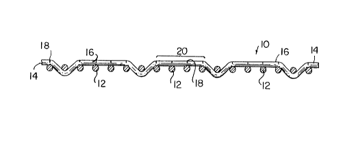
Figure 5 is a side view of a forming fabric
mounted and under tension on a finishing table. Its
surface is being treated with a cutting tool to
provide the slits or scores for reducing edge curl.
Detailed Description of the Preferred Embodiment
To illustrate the edge curl problem that can be
reduced by the method of the present invention,
reference is made to Figures 1 and 2. Figure 1
presents a cross-sectional view of a forming fabric 10
made up of monofilament machine-direction yarns 12
interwoven with monofilament cross-machine direction
yarns 14. The long-chute knuckle side 16, often used
to form the paper sheet, is characterized by chute
knuckles that are broad and flat. This is a
consequence of the 1 x 4 weave pattern in which the
6
CA 02203025 1997-04-17
WO 97/09479 PCT/US96/02493
cross-machine direction yarn 14 spans four machine-
direction yarns 1 for each one it weaves under.
The fact that most of the length of the cross-
machine direction yarn 14 lies on the long-shute
knuckle side 16 of the machine direction yarn 12
causes the forces acting upon the fabric in the cross-
machine direction when shrinkage occurs to be unequal.
The rather exaggerated curl shown in Figure 2 results.
The method disclosed here is an attempt to remedy this
effect .
Referring to Figure 3, a cross-sectional view
similar to that shown in Figure 1, monofilament cross-
machine direction yarns 14 of forming fabric 10 are
provided with at least one slit or score 18 per
knuckle 20 on the long-shute knuckle side 16. The
depth of the slits or scores 18 is preferably no
greater than one-half of the diameter of the cross-
machine direction yarn 14.
Figure 4 is a perspective view of a typical
endless forming fabric 30. The entire surface of the
forming fabric 10 may be provided with slits or scores
18 in accordance with the present invention. However,
as an option, only regions lying in a band 22 along
each of the two lateral edges of the forming fabric
10
and not extending into the central region 24 could be
provided with slits or scores 18. The width of the
bands 22 could be chosen to be of a width not
extending into the central region 24 of the forming
fabric l0 used to form a paper sheet.
The method of the present invention can be
practiced as follows. Referring to Figure 5, the
forming fabric 10, either woven in endless form or
joined into such a form by seaming, is mounted on a
finishing table, which consists of a first roll 26 and
7
CA 02203025 1997-04-17
WO 97/09479 PCT/US96/02493
a second roll 28, which can be moved apart to place
the forming fabric 10 under tension.
A scoring blade 30 is suspended above the forming
fabric 10. The scoring blade 30 is then brought into '
slight contact with the forming fabric and operated to
provide at least one slit or score 18 per knuckle 20
to the cross-machine direction yarns 14 on the long-
shute knuckle side 16 of the forming fabric 10. This
process may be carried out by having the scoring blade
30 move in one direction while the finishing table
rollers 26, 28 move the forming fabric 10 in the
opposite direction, as indicated by the arrows in
Figure 5.
For example, in an 84-mesh fabric, wherein the
cross-machine direction yarns 14 are woven in an
"under one and over four" pattern, slits or scores 18
separated transversely by a distance of 1.21 mm would
provide the minimum one slit or score 18 per knuckle
on the long-chute knuckle side 16. A smaller
20 separation, such as, for example, by one-half or one-
fourth that distance, would provide two or four slits
or scores 18 per knuckle 20, the latter of which is
shown in Figure 3. In any event, either the entire
long-shute knuckle side 16 of the forming fabric 10 or
only regions lying in a band 22 along each of the two
lateral edges thereof may be so treated in accordance
with the present invention.
Although the method provided by the present
invention has been described and illustrated for a
single-layered forming fabric of specific weave, it
should be understood by the reader that it can be
applied as well to other kinds of forming fabrics,
both single- and multi-layered, having weave patterns
such that edge curl may arise in response to
unbalanced forces produced across the fabric by the
8
CA 02203025 1997-04-17
WO 97/09479 PCT/US96/02493
shrinkage of cross-machine direction (CD) yarns. In
general, then, one would treat the fabric as disclosed
herein on the paper-supporting side of the fabric.
Modifications would be obvious to one skilled in
the art without departing from the scope of the
invention as defined in the appended claims.
9