Sélection de la langue

Search

Sommaire du brevet 2204586 

Énoncé de désistement de responsabilité concernant l'information provenant de tiers

Une partie des informations de ce site Web a été fournie par des sources externes. Le gouvernement du Canada n'assume aucune responsabilité concernant la précision, l'actualité ou la fiabilité des informations fournies par les sources externes. Les utilisateurs qui désirent employer cette information devraient consulter directement la source des informations. Le contenu fourni par les sources externes n'est pas assujetti aux exigences sur les langues officielles, la protection des renseignements personnels et l'accessibilité.

Disponibilité de l'Abrégé et des Revendications

L'apparition de différences dans le texte et l'image des Revendications et de l'Abrégé dépend du moment auquel le document est publié. Les textes des Revendications et de l'Abrégé sont affichés :

  • lorsque la demande peut être examinée par le public;
  • lorsque le brevet est émis (délivrance).
(12) Brevet: (11) CA 2204586
(54) Titre français: STENT MULTICELLULAIRES A CELLULES A CARACTERISTIQUES DIFFERENTES
(54) Titre anglais: MULTI-CELL STENT WITH CELLS HAVING DIFFERING CHARACTERISTICS
Statut: Périmé
Données bibliographiques
(51) Classification internationale des brevets (CIB):
  • A61F 2/915 (2013.01)
  • A61F 2/856 (2013.01)
  • A61F 2/958 (2013.01)
(72) Inventeurs :
  • FISCHELL, ROBERT E. (Etats-Unis d'Amérique)
  • FISCHELL, TIM A. (Etats-Unis d'Amérique)
  • FISCHELL, DAVID R. (Etats-Unis d'Amérique)
(73) Titulaires :
  • CORDIS CORPORATION (Non disponible)
(71) Demandeurs :
  • FISCHELL, ROBERT E. (Etats-Unis d'Amérique)
  • FISCHELL, TIM A. (Etats-Unis d'Amérique)
  • FISCHELL, DAVID R. (Etats-Unis d'Amérique)
(74) Agent: GOWLING WLG (CANADA) LLP
(74) Co-agent:
(45) Délivré: 2004-07-27
(22) Date de dépôt: 1997-05-06
(41) Mise à la disponibilité du public: 1997-12-11
Requête d'examen: 2001-07-09
Licence disponible: S.O.
(25) Langue des documents déposés: Anglais

Traité de coopération en matière de brevets (PCT): Non

(30) Données de priorité de la demande:
Numéro de la demande Pays / territoire Date
08/661,562 Etats-Unis d'Amérique 1996-06-11

Abrégés

Abrégé français

La présente invention est une endoprothèse multicellulaire dotée d'au moins deux types différents de cellules, chaque type de cellules étant prévu pour une fin différente. Par exemple, un premier type de cellule est conçu pour offrir une rigidité radiale maximale après le déploiement de l'endoprothèse. Un deuxième type de cellules est conçu pour offrir une souplesse longitudinale accrue avant le déploiement de l'endoprothèse et après le déploiement de l'endoprothèse dans une artère principale. Le deuxième type de cellules peut facilement consister en un ballonnet déployé à l'ostium d'une artère ramifiée pour atteindre un diamètre large, par comparaison, sans qu'aucune des branches de la cellule d'endoprothèse ne se rompe. Cette technique rend possible l'écoulement non obstrué du sang dans la branche.


Abrégé anglais

The present invention is a multi-cell stent having at least two different types of cells with each type of cell accomplishing a different purpose. For example, a first type of cell is intended to provide a maximum radial rigidity after stent deployment. A second type of cell is designed to provide increased longitudinal flexibility prior to stent deployment and after stent deployment into a main artery, the second type of cell can be readily balloon expanded at the ostium of a side branch artery to a comparatively large diameter without breaking any of the struts of the scent cell. By this technique, unobstructed blood flow into the side branch can be provided.

Revendications

Note : Les revendications sont présentées dans la langue officielle dans laquelle elles ont été soumises.


11
What is claimed is:
1. A multi-cell stent structure integrally formed as a thin-walled cylinder,
the stent
having a multiplicity of cells each having a closed perimeter formed from
thin, wire-like
struts and curved sections and each cell having two longitudinally separated
ends, the
perimeter of at least some of the cells of the multi-cell stent including a
pair of vertical
struts extending in a generally circumferential direction and being
longitudinally
displaced each with respect to the other at the longitudinally separated ends
of each cell,
each vertical strut having two curved end sections each being joined to a
diagonal strut
thereby forming a pair of diagonal struts connected to the two curved end
sections of
each vertical strut, at least one cell of the multi-cell stent being an
expandable cell which
includes within its perimeter at least one undulating strut, the undulating
strut being
adapted to provide increased longitudinal flexibility to the multi-cell stent
and each
expandable cell having a longer perimeter length as compared to the perimeter
length of
at least one other type of cell of the multi-cell stent.
2. The stent of claim 1 wherein there are not more than two different types of
cells
which make up the multi-cell stent.


12
3. The stent of claim 1 wherein the undulating strut of the expandable cell is
an S-
strut which provides the stent with additional longitudinal flexibility prior
to stent
deployment, the S-strut also providing additional perimeter length for each
expandable
cell as compared to the perimeter length of the at least one other cell of the
multi-cell
stent.
4. The stent of claim 1 wherein the expandable cells have a perimeter length
that is
at least 10% greater as compared to the perimeter length of the at least one
other type of
cell.
5. The stent of claim 1 wherein the at least one other type of cell is adapted
for
increasing post-deployment radial rigidity and the expandable cell is adapted
to be
expanded to a generally circular shape by means of an inflatable balloon that
is placed
through the closed perimeter of the expanded cell, the balloon being inflated
within the
expandable cell to a pressure exceeding three atmospheres.
6. The stent of claim 1 wherein the stent consists of a multiplicity of
cylindrical segments, each cylindrical segment consisting of only one


13
type of cell, each cylindrical segment having at least three cells disposed
circumferentially and being one cell wide in the longitudinal direction.
7. The stent of claim 6 wherein the stent has at least one cylindrical segment
of
expandable cells which expandable cells are adapted to be expanded to a
generally
circular shape by means of an inflatable balloon that is placed through the
closed
perimeter of an expandable cell and then inflated within that cell to a
pressure exceeding
three atmospheres.
8. The stent of claim 6 wherein the stent has at least three cylindrical
segments of
expandable cells.
9. The stent of claim 8 wherein the stent has a longitudinally centered,
center
section into which three adjacent cylindrical segments of expandable cells are
located.
10. The stent of claim 7 wherein the stent has a longitudinal axis and the
inflatable
balloon has a longitudinal axis and the inflatable balloon is placed through
one
expandable cell with its longitudinal axis placed approximately perpendicular
to the
longitudinal axis of the stent.


14


11. A multi-cell stent adapted for placement at a side branch artery of a main
artery
of the human body, the stent structure being in the general form of a thin-
walled
cylinder consisting of a multiplicity of cells, each cell having a closed
perimeter
consisting of a series of wire-like struts and curved sections which are
integrally joined
together, the stent having a first type of cell whose perimeter includes at
least one
undulating strut adapted to increase the stent's flexibility, the perimeter of
the first type
of cell being greater in length as compared with the perimeter length of a
second type of
cell of the stent, the stent also having a longitudinally centered, center
section wherein at
least one cylindrical segment is located, each cylindrical segment at the
stent's center
section consisting of at least three of the first type of cells placed
circumferentially and
being one cell wide in the longitudinal direction.

12. The stent of claim 11 wherein there are not more than two different types
of cells
which make up the multi-cell stent.

13. The stent of claim 11 wherein the undulating strut of the first type of
cell is an
S-strut which provides the stent with additional longitudinal flexibility
prior to stent
deployment, the S-strut also providing additional perimeter length for the
first type of
cell as compared to the perimeter length of the second type of cell.


15
14. The stent of claim 11 wherein the first type of cell has a perimeter
length that is
at least 10% greater as compared to the perimeter length of the second type of
cell.
15. The stent of claim 11 wherein the second type of cell is adapted for
increasing
post-deployment radial rigidity and the first type of cell is adapted to be
expanded to a
generally circular shape by means of an inflatable balloon that is placed
through the
closed perimeter of the first type of cell, the balloon being inflated within
that the first
type of cell to a pressure exceeding three atmospheres.
16. The stent of claim 11 wherein the stent consists of a multiplicity of
cylindrical
segments, each cylindrical segment consisting of only one type of cell, each
cylindrical
segment having at least three cells disposed circumferentially and being one
cell wide in
the longitudinal direction.
17. The stent of claim 16 wherein the stent has at least one cylindrical
segment of
the first type of cells which cells are adapted to be expanded to a generally
circular
shape by means of an inflatable balloon that is placed through the closed
perimeter of the
first type of cell and then inflated within that cell to a pressure exceeding
three
atmospheres.
18. The stent of claim 16 wherein the stent has at least three cylindrical
segments
consisting of only the first type of cells.


16
19. The stent of claim 18 wherein the stent has a longitudinally centered,
center
section into which three adjacent cylindrical segments of the first type of
cells are
located.
20. The stent of claim 17 wherein the stent has a longitudinal axis and the
inflatable
balloon has a longitudinal axis and the inflatable balloon is placed through
one of the
first type of cells with its longitudinal axis placed approximately
perpendicular to the
longitudinal axis of the stent.

Description

Note : Les descriptions sont présentées dans la langue officielle dans laquelle elles ont été soumises.


CA 02204586 1997-OS-06
MULTI-CELL STENT WITH CELLS RAVING DIFf~RING
CHARACTERISTICS
FIELD OF USE
The present invention is an expandable stent insertable into a vessel of a
human body for
the purpose of creating and maintaining the patency of that vessel.
BACKGROUND OF THE INVENTION
Some of the earliest stems were merely helical coils that expanded radially
outward after
being placed in a vessel of a human body. More recent stents have used uniform
cellular
structures with the stent typically being expanded radially outward into a
vessel by
means of a balloon located at a distal portion of a balloon angioplasty
catheter. After
radial expansion, some of these stents have struts or wires that tend to block
a side
branch artery which comes off a main artery into which the stmt has been
placed. With
an expandable balloon, it is possible to break open a strut of a particular
cell of such a
stmt where the struts of that cell are impeding blood flow into that side
branch.
However, breaking open such a cell can leave strut ends protruding into the
lumen of the
side branch or the main artery itself which is highly undesirable. Also,
breaking a cell
open weakens the stmt structure.

CA 02204586 1997-OS-06
2
SUMMARY OF THE INVENTION
The present invention is a mufti-cell stent having at least two different
types of cells with
each type of cell accomplishing a different purpose. For example, a first type
of cell is
intended to provide a maximum radial rigidity after stent deployment. A second
type of
cell is designed to provide increased longitudinal flexibility prior to stent
deployment and
after stent deployment into a main artery, the second type of cell can be
readily balloon
expanded at the ostium of a side branch artery to a comparatively large
diameter
without breaking any of the struts of the stent cell. By this technique,
unobstructed
blood flow into the side branch can be provided.
Thus an object of this invention is to have a mufti-cell stmt with at least
two different
types of cells.
Another object of this invention is to have a stmt in which one type of cell
has
enhanced radial rigidity after stent deployment and a second type of cell
provides
increased flexibility prior to deployment and after deployment that cell can
be balloon
expanded into a generally circular shape thereby causing all stent struts to
be moved
away from the opening of a side branch of a main artery.
Still another objective of this invention is to have ring-like, cylindrical
segments of the
stem which segments are made up of only one type of cell of the mufti-cell
stmt.

CA 02204586 1997-OS-06
3
These and other important objects and advantages of this invention will become
apparent
from the detailed description of the invention and the associated drawings
provided
herein.
BRIEF DESCRIPTION OF THE DRAWINGS
FIG. 1 is a cross-sectional view of a main artery with a prior art stent
deployed with
partial blockage of the side branch.
FIG. 2 illustrates one embodiment of the present invention represented as a
flat, 2-
dimensional plan view of a mufti-cell cylindrical stent prior to deployment.
FIG. 3 shows a 2-dimensional representation of the cylindrical stmt of FIG. 2
as it
would appear after deployment.
FIG. 4A illustrates a deployed mufti-cell stmt placed in a main artery with
some stent
struts partially blocking a side branch artery. FIG. 4B illustrates the
deployed stent of
FIG. 4A with an inflatable balloon advanced over a guide wire and into the
side branch
artery.

CA 02204586 1997-OS-06
4
FIG. 4C shows the balloon of FIG. 4B expanded so that the stmt struts are
pushed away
from the ostium of the side branch artery.
FIG. 4D shows the guide wire and balloon removed with the stmt struts no
longer
blocking the ostium of the side branch artery.
FIG. 5 is an enlarged cross-sectional view looking down the side branch artery
at
section 5-5 of FIG. 4A.
FIG. 6 is an enlarged cross-sectional view looking down the side branch artery
at section
6-6 of FIG. 4D.
FIG. 7 is a 2-dimensional representation of an alternative embodiment of the
present
invention in which a multi-cell, pre-deployed stent has three cylindrical
segments of
special expandable cells placed at the center of the stent.
DETAILED DESCRIPTION OF TI3E INVENTION
FIG. 1 shows a prior art stmt 1 that has been deployed radially outward into a
main
artery 5. The stent 1 has many struts (or wires) 2, and specifically, strut
segments 3 and
4 of two such wires 2 have been deployed in such a manner as to partially
obstruct the
ostium or mouth of the side branch artery 6. This condition has been termed "
stent

CA 02204586 1997-OS-06
jail" . Because of the obstructing position of the segments 3 and 4, blood
flow into the
lumen 7 of the side branch 6 is compromised. Furthermore, the wires 3 and 4
can block
the passage of a second stent from entering the lumen 7 of the side branch 6.
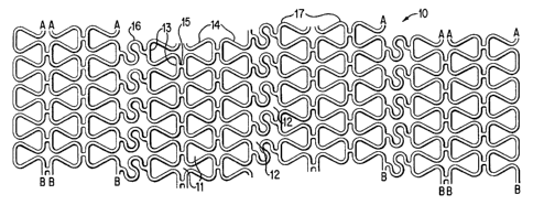
One embodiment of the present invention as shown in FIG. 2, is a pre-deployed
cylindrical stent 10 as it would appear if it were cut longitudinally and then
extended out
into a flat, 2-dimensional configuration. It should be clearly understood that
the stmt 10
is in fact cylindrical in shape, which cylindrical shape would be obtained by
rolling the
flat configuration of FIG. 2 into a cylinder with all points "A" joined to all
points "B" .
The stent 10 is typically fabricated by laser machining of a thin-walled,
cylindrical,
stainless steel tube.
The stent 10 has exactly two different types of cells: namely, structural
cells 11 and
special expandable cells 12. Both these cells are formed from vertical struts
13 each
having two curved end sections 17, each end section being joined to a diagonal
strut 14.
Some of the
vertical struts 13 are joined with horizontal H-bars 15 which form part of the
perimeter
of the cells 11, and some of the vertical struts 13 are joined by undulating S-
struts 16
which form part of the perimeter of the expandable cells 12.
FIG. 3 is a 2-dimensional representation of the cylindrical stent 10' after
deployment;
i.e., after radially outward dilatation. FIG. 3 shows how the pre-deployed
stent 10 of

CA 02204586 1997-OS-06
6
FIG. 2 is configured after deployment to the stent 10' shown in FIG. 3. FIG. 3
also
shows the deployed structural cells 11', the deployed special expandable cells
12', the
vertical struts 13', the diagonal struts 14' the curved end section 17 ', the
H-bars 15
and the S-struts 16. Neither the H-bars 15 nor the S-struts 16 change shape
when the
stent 10 is deployed to form the stent 10'.
It should be noted that both the cells 11 and 11' and 12 and 12' are formed
into ring-like
circumferential, cylindrical segments with (in this case) exactly five cells
per cylindrical
segment. Typically a mufti-cell stent would have at least three cells per
cylindrical
segment disposed circumferentially, and all cylindrical segments are one cell
wide in the
longitudinal direction. From either FIG. 2 or FIG. 3 it is clear to see that
the stent 10 or
10' has exactly 8 cylindrical segments of structural cells 11 and 3
cylindrical segments of
expandable cells 12 or 12' .
Prior to deployment, the S-struts of the stent 10 provide greatly enhanced
longitudinal
flexibility for the stent 10. This allows for easier placement of the stent 10
through
highly curved coronary arteries. FIGS. 2 and 3 clearly show that the H-bar 15
is much
shorter in length as compared to the S-strut 16. Therefore, the perimeter of
the cells 12'
is significantly longer that the perimeter of the cells 11' . Therefore, as
compared to a
cell 11', not only is it easier to expand a cell 12' by placing a balloon
within that cell

CA 02204586 1997-OS-06
7
and inflating that balloon to a high pressure, but any cell 12' is also
expandable to a
greater diameter as compared to any cell 11' . Ideally, the perimeter length
of the
expandable cell 12 ' should be at least 10 % longer than the perimeter length
of the cells
11'.
FIG. 4A shows the stent 10' deployed into a main artery 5 with two of the
diagonal
struts 14' blocking the lumen 7 of the side branch 6. It should be noted that
the struts
14' would be part of the perimeter of an expanded cell 12' . A guide wire 20
can be
placed through the expandable cell 12' , and the guide wire 20 can then be
advanced into
the lumen 7 of the side branch 6. As shown in FIG. 4B, a balloon angioplasty
catheter
30 can then be advanced over the guide wire 20, through the expanded cell 12'
, and
into the lumen 7. As seen in FIG. 4B, the balloon 32 is placed mostly into the
side
branch 6, but it also extends partially into the main artery 5. A liquid at a
pressure of
at least 3 atmospheres, (but typically 10 to 16 atmospheres), is then injected
into the
balloon 32 which causes it to become the inflated balloon 32' as shown in FIG.
4C.
The inflated balloon 32 causes longitudinal displacement of the diagonal
struts 14' so as
to form the struts 14" which become part of the newly shaped stent 10" both as
shown
in FIG. 4C. Furthermore, the inflated balloon 32' causes the perimeter of the
expandable cell 12' to assume a generally circular shape without the breakage
of any
strut. The balloon 32' is then deflated, and the guide wire 20 and balloon
angioplasty
catheter 30 are removed from the side branch artery 6 and the main artery 5.
The stmt

CA 02204586 1997-OS-06
10" then appears as shown in FIG. 4D. It should be pointed out that the
balloon 32'
can not only move struts so as to "unjail" a side branch, but the balloon 32'
can also
perform balloon dilatation of any stenotic narrowing at or near the ostium (or
mouth) of
any side branch artery into which the balloon 32' is advanced.
For the sake of clarity, FIGS. 4A, 4B, 4C and 4D show only those parts of the
stent 10'
and 10" that are located at the center of the main artery 5.
FIG. 5 is a cross-sectional view looking down the side branch artery 6 showing
the
portion of the stent 10' that has been deployed into the ostium of the side
branch artery
5. Note that the S-strut 16 has not changed in shape when the stent 10 is
deployed into
the main artery to form the stent 10' . Although the cell 12' is more open
that the cell
12, the diagonal struts 14', the vertical struts 13' and the S-strut 16 each
can cause
some blockage of the ostium of the side branch artery 6.
FIG. 6 is a cross-sectional view looking down the side branch artery 6 after
the balloon
32 has been inflated to form the balloon 32' and the balloon angioplasty
catheter 30 has
been removed. Only that portion of the stent 10" which is positioned at the
ostium of
the side branch 6 is shown in FIG. 6. It is easily seen that virtually all of
the struts that
were shown in FIG. 5 to be blocking blood flow to the side branch artery 6
have been
moved aside. Specifically, the diagonal struts 14' have been moved away from
the

CA 02204586 1997-OS-06
9
center of the ostium of the side branch to form the struts 14", and the S-
strut 16 has
been moved aside to form the S-strut 16' . Therefore, blood flow to the side
branch
artery 6 is improved, and one could then readily place another stmt (not
shown) through
the ostium and into the lumen 7 of the side branch artery 6 in order to treat
an ostial
stenosis (not shown).
FIG. 7 shows a 2-dimensional view of a pre-deployed stent 40 which is a second
embodiment of the present invention. Like the stmt 10, the stent 40 is ideally
suited for
placement at the ostium of a side branch artery. The stent 40 has three
circumferential
cylindrical segments of the special expandable cells 43 placed at the
longitudinal center
of the stmt 40. All other cells of the stent 40 are structural cells 42.
Having three
cylindrical segments of special expandable cells 13 at the center of the stmt
40 has the
advantage of requiring less accuracy for the placement of the center of the
stent 40 at a
side branch artery.
The fact that both the stents 10 and 40 have cylindrical segments in which all
the cells
of one segment are identical makes it possible for the stmt implanting
physician to place
a special expandable cell at a side branch without requiring any knowledge of
the stmt's
angular position about the stent's longitudinal axis. This would not be the
case if there
was more than one type of cell in a cylindrical segment.

CA 02204586 1997-OS-06
Although the description herein has been applied only to the vessels that are
arteries, it
should be understood that the apparatus and method described herein could also
be
applied to other types of vessels of the human body such as bronchial tubes in
the lung
or the bile duct in the liver.
Various other modifications, adaptations, and alternative designs are of
course possible
in light of the above teachings. Therefore, it should be understood at this
time that
within the scope of the appended claims, the invention may be practiced
otherwise than
as specifically described herein.

Dessin représentatif
Une figure unique qui représente un dessin illustrant l'invention.
États administratifs

Pour une meilleure compréhension de l'état de la demande ou brevet qui figure sur cette page, la rubrique Mise en garde , et les descriptions de Brevet , États administratifs , Taxes périodiques et Historique des paiements devraient être consultées.

États administratifs

Titre Date
Date de délivrance prévu 2004-07-27
(22) Dépôt 1997-05-06
(41) Mise à la disponibilité du public 1997-12-11
Requête d'examen 2001-07-09
(45) Délivré 2004-07-27
Expiré 2017-05-10

Historique d'abandonnement

Il n'y a pas d'historique d'abandonnement

Historique des paiements

Type de taxes Anniversaire Échéance Montant payé Date payée
Enregistrement de documents 100,00 $ 1997-05-06
Le dépôt d'une demande de brevet 300,00 $ 1997-05-06
Taxe de maintien en état - Demande - nouvelle loi 2 1999-05-06 100,00 $ 1999-03-17
Taxe de maintien en état - Demande - nouvelle loi 3 2000-05-08 100,00 $ 2000-03-23
Taxe de maintien en état - Demande - nouvelle loi 4 2001-05-07 100,00 $ 2001-03-19
Requête d'examen 400,00 $ 2001-07-09
Taxe de maintien en état - Demande - nouvelle loi 5 2002-05-06 150,00 $ 2002-02-25
Taxe de maintien en état - Demande - nouvelle loi 6 2003-05-06 150,00 $ 2003-04-08
Taxe de maintien en état - Demande - nouvelle loi 7 2004-05-06 200,00 $ 2004-02-26
Taxe finale 300,00 $ 2004-05-14
Taxe de maintien en état - brevet - nouvelle loi 8 2005-05-06 200,00 $ 2005-05-03
Paiement des arriérés de taxes 400,00 $ 2005-05-25
Taxe de maintien en état - brevet - nouvelle loi 9 2006-05-08 200,00 $ 2006-04-07
Taxe de maintien en état - brevet - nouvelle loi 10 2007-05-07 250,00 $ 2007-04-10
Taxe de maintien en état - brevet - nouvelle loi 11 2008-05-06 250,00 $ 2008-04-10
Taxe de maintien en état - brevet - nouvelle loi 12 2009-05-06 250,00 $ 2009-04-20
Taxe de maintien en état - brevet - nouvelle loi 13 2010-05-06 250,00 $ 2010-04-14
Taxe de maintien en état - brevet - nouvelle loi 14 2011-05-06 250,00 $ 2011-04-13
Taxe de maintien en état - brevet - nouvelle loi 15 2012-05-07 450,00 $ 2012-04-11
Taxe de maintien en état - brevet - nouvelle loi 16 2013-05-06 450,00 $ 2013-04-10
Taxe de maintien en état - brevet - nouvelle loi 17 2014-05-06 450,00 $ 2014-04-09
Taxe de maintien en état - brevet - nouvelle loi 18 2015-05-06 450,00 $ 2015-04-15
Taxe de maintien en état - brevet - nouvelle loi 19 2016-05-06 450,00 $ 2016-05-02
Titulaires au dossier

Les titulaires actuels et antérieures au dossier sont affichés en ordre alphabétique.

Titulaires actuels au dossier
CORDIS CORPORATION
Titulaires antérieures au dossier
FISCHELL, DAVID R.
FISCHELL, ROBERT E.
FISCHELL, TIM A.
Les propriétaires antérieurs qui ne figurent pas dans la liste des « Propriétaires au dossier » apparaîtront dans d'autres documents au dossier.
Documents

Pour visionner les fichiers sélectionnés, entrer le code reCAPTCHA :


Pour visualiser une image, cliquer sur un lien dans la colonne description du document. Pour télécharger l'image (les images), cliquer l'une ou plusieurs cases à cocher dans la première colonne et ensuite cliquer sur le bouton "Télécharger sélection en format PDF (archive Zip)" ou le bouton "Télécharger sélection (en un fichier PDF fusionné)".

Liste des documents de brevet publiés et non publiés sur la BDBC .

Si vous avez des difficultés à accéder au contenu, veuillez communiquer avec le Centre de services à la clientèle au 1-866-997-1936, ou envoyer un courriel au Centre de service à la clientèle de l'OPIC.


Description du
Document 
Date
(yyyy-mm-dd) 
Nombre de pages   Taille de l'image (Ko) 
Revendications 1997-05-06 6 157
Description 1997-05-06 10 295
Dessins 1997-05-06 4 163
Dessins représentatifs 1998-02-09 1 6
Dessins représentatifs 2003-10-31 1 26
Page couverture 1998-02-09 1 48
Abrégé 1997-05-06 1 16
Page couverture 2004-06-29 1 56
Cession 1997-05-06 2 97
Poursuite-Amendment 2001-07-09 1 35
Poursuite-Amendment 2001-10-12 1 32
Taxes 2003-04-08 1 31
Taxes 2001-03-19 1 28
Taxes 1999-03-17 1 32
Taxes 2002-02-25 1 40
Cession 2004-02-11 3 122
Taxes 2000-03-23 1 30
Taxes 2004-02-26 1 34
Correspondance 2004-05-14 1 34
Taxes 2005-05-03 1 28
Correspondance 2005-06-06 1 15