Note : Les descriptions sont présentées dans la langue officielle dans laquelle elles ont été soumises.
CA 02206299 2004-04-20
51269-1
1
LINERLESS LABEL CUT-OFF
BACKGROUND AND SUMMARY OF THE INVENTION
The use of linerless labels is becoming widespread
due to relatively low cost of such labels and due to their
relative environmental friendliness. A number of different
dispensers has been developed -- such as shown in
U.S. Patents 5,375,752 and 5,417,783, European published
application 0577241, and PCT Publication No. W09610489 A1 --
to facilitate dispensing of such labels. Each of those
dispenser is particularly suited for certain dispensing
requirements and can successfully dispense linerless labels
without prohibitive difficulties. However, there are some
circumstances for which such dispensers are not ideally
suited and therefore the linerless label dispenser according
to the present invention -- and its associated cutting
mechanism -- have been developed.
The linerless label dispenser, and its associated
cutting mechanism, according to the present invention are
ideally suited for dispensing linerless labels from a roll
even when the labels are not perforated on the roll. The
dispenser can automatically print the labels just prior to
dispensing, and dispenses them in a manner that
substantially avoids jamming of the printer or the cutting
mechanism.
According to one aspect of the present invention a
linerless label dispenser is provided comprising the
following components: A support for a supply of continuous
form linerless labels, each label having a pressure
sensitive adhesive face and an adhesive-release material
coated face. An adhesive-release material guide structure
for engaging the adhesive
CA 02206299 2004-04-20
51269-1
2
face of labels from the supply of labels. A print head, on the opposite
side of the guide structure from the supply of labels, for printing the
release material coated face of labels from the supply of labels. A
stripper surface, on the opposite side of the print head from the release
material structure, the stripper surface of adhesive-release material. A
stationary anvil blade, on the opposite side of the stripper surface from
the print head, for engaging the adhesive face of labels from the supply of
labels. And an automatic rotary cutter cooperating with the st~tion~ry
anvil blade far engaging the release material coated face of labels from
the supply of labels, and cutting indivicual IGbels to be dispensed from the
supply of continuous form of linerless labels.
The support for the continucus fcrm linerless labels preferably
comprises a conventional shaft for supporting the core of a roll of linerless
labels. The lineriess labels may either be perforated, or may have marks
applied thereto indicating the approximate position at whic;~ the web of
labels from the roll are to be severed into individual labels.
The adhesive-release material guide structure may be mounted
adjacent a plastic guide which engages the release material face of the
labels, and preferably the adhesive-release material thereof is a plasma
coating such as disclosed in U.S. Patent 5,375,752 ,
After the guide structure of the labels typically pass under a sensor
which either senses the perforations or marks indicating the division
between labels, which cooperates with a control mechanism for the
printer and subsequent rotary cutter. The print head may be of any
conventional type that is capable or' printing on the release material,
pr~farably a non-impact printer such as an ink jet printer. Where a
CA 02206299 1997-OS-28
WO 97/14616 PCT/US96/16480
3
thermosensitive coating is also provided for the labels, the print head may
be a thermal print head or a thermal transfer print head. Typically the
print head cooperates with a print roller, which also is plasma coated.
(The print roller in the case of thermal or ink jet is made of a silicone
covered core, available from Silicone Products & Technology, Inc. of
Lancaster, NY. )
Just downstream of the print head is a support which supports the
stripper surface and the stationary anvil blade. The adhesive-release
material of the stripper surface preferably also is a plasma coating, and
the stripper surface is disposed at an upwardly directed (from the print
head) angle of between about 20-35° (preferably about 27°) with
respect
to the horizontal so that the labels printed by the print head move
upwardly at an angle from the print head to the rotary cutter. The
provision of such an angle has been found to minimize jams of the printer
and the cutter. A stripper surface also may have a plurality of upwardly
extending extensions formed on at least a part thereof (e.g. a portion of
between 5-20% of the width of a linerless label passing thereover) for
decreasing the surface tension thereof.
The stationary anvil blade is preferably also plasma coated and is
immediately adjacent the stripper surtace. Alternatively, the stationary
block may be painted with a textured paint. (The actual cutting surfaces
are not plasma coated or textured painted; just the supporting pieces. ) It
has been found according to the present invention that jamming of the
printer and rotary cutter are minimized if the anvil blade is spaced
downwardly from a stripper surface a sufficient distance to insure that the
leading edge of the label (the edge being cut) is not smashed. It has
CA 02206299 2004-04-20
51269-1
4
been found that a spacing of between about .001-.008 inches (preferably
about .002-.004 inches) is most effective.
The rotary cutter may comprise a conventional off the shelf
structure, except for the plasma coated rotary blade, such as a Hitachi
rotary cutter Model #V1 SA.
Under some circumstances it is desirable to have an exit roller
downstream of the rotary cutoff mechanism to facilitate dispensing of the
cut labels, such as through an exit opening in a housing. Such an exit
roller, when provided, also pref=rably has a plasma coated surface, and
that surface is also preferably grooved (between about 8-20% of the width
of a linerless label engaged thereby) and typically cooperates with a hold
down mechanism of ary conventional type.
According to another aspect of the present invention a cutting
mechanism per se for linerless labels (each having a pressure sensitive
adhesive face and an adhesive-release material coated faC~) is provided.
The cutting mechanism comprises the following elements: A stripper
surface of adhesive-release material for engaging the adhesive face of
linerless labels, and making an angle with respect to the horizontal of
between 20-35 degrees. A stationary anvil blade adjacent the stripper
surface for engaging the adhesive face of linerless labels. And a rotary
cutter cooperating with the staticnary anvil blade for engaging the release
material coated face cf lirerless labels and cutting the labels.
The rotary cutter typically inc;udes a rotary blade and the
stationary and rotary blades are preferably plasma coated cr texturs
painted. The orientaticn and dimensioning of the stripper surface and
anvil blade preferably are as described above for the dispenser.
CA 02206299 2004-04-20
51269-1
4a
Thus, in a broad aspect the invention provides a
linerless label dispenser, comprising: a support for a
supply of continuous form linerless labels, each label
having a pressure sensitive adhesive face and an adhesive-
release material coated face; means for moving the labels
from the supply of labels through the dispenser; a guide
structure having adhesive-release material thereon for
engaging the adhesive face of labels from said supply of
labels and guiding the labels for movement in a downstream
direction; a print head on a downstream side of said guide
structure from said supply of labels, for printing the
release material coated face of labels from said supply of
labels; a stripper surface, on the downstream side of said
print head from said guide structure, said stripper surface
having adhesive-release material thereon for contacting the
adhesive face of the labels; a stationary anvil blade,
downstream of said stripper surface from said print head,
for engaging the adhesive face of labels from said supply of
labels; and an automatic rotary cutter cooperating with said
stationary anvil blade for engaging the release material
coated face of labels from said supply of labels, and
cutting individual labels to be dispensed from said supply
of continuous linerless labels; wherein the stripper surface
is substantially planar and is disposed at an upwardly
directed angle of between 20 to 35 degrees with respect to
the horizontal so that labels printed by said print head
move upwardly at an angle from said print head to said
rotary cutter.
In another aspect the invention provides a
feeding, guiding and cutting mechanism in a label dispenser
for linerless labels each having a pressure sensitive
adhesive face and an adhesive-release material coated face,
said mechanism comprising: a feeding mechanism for moving a
CA 02206299 2004-04-20
51269-1
4b
continuous web of linerless labels towards a rotary cutter,
a stripper surface of adhesive-release material for engaging
the adhesive face of the continuous web of linerless labels,
and guiding the labels up the stripper surface to the rotary
cutter, the stripper surface making an angle with respect to
the horizontal of between 20-35 degrees; a stationary anvil
blade adjacent the downstream end of said stripper surface
in the direction of label movement, for engaging the
adhesive face of linerless labels leaving the stripper
surface; and the rotary cutter cooperating with said
stationary anvil blade for engaging the release material
coated face of linerless labels and cutting the labels from
the web.
CA 02206299 1997-OS-28
WO 97/14616 PCT/US96/16480
It is a primary object of the present invention to provide an effective
linerless label dispenser and a cutting mechanism for use therewith. This
and other objects of the invention will become clear from an inspection of
the detailed description of the invention, and from the appended claims.
5
BRIEF DESCRIPTION OF THE DRAWINGS
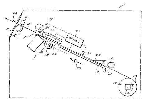
FIGURE 1 is a side schematic view of an exemplary linerless label
dispenser according to the present invention;
FIGURE 2 is a detail side elevational view, with portions cut away
for clarity of illustration, of the stripper surface and cutting mechanism of
the dispenser of FIGURE 1;
FIGURE 3 is an enlarged partial front end view of the stripper
surface of FIGURES 1 and 2 showing the linerless label, also enlarged for
clarity of illustration, in association therewith; and
FIGURE 4 is a partial front end view of an exemplary construction
of an exit roller of the dispenser of FIGURE 1.
DETAILED DESCRIPTION OF THE DRAWINGS
FIGURE 1 schematically illustrates an exemplary dispenser that
may be provided according to the present invention for dispensing
linerless labels e.g. in a roll 10 which is a supply of continuous form
linerless labels. The linerless labels in the roll 10 may either have
CA 02206299 1997-OS-28
WO 97/14616 PCT/US96/16480
6
perforations between the labels, or may be devoid of perforations.
Sensor marks may be provided so that when a label begins and ends
may be determined. The dispenser illustrated in FIGURE 1 may include a
common housing shown merely in dotted lines schematically at 11 in
FIGURE 1.
The supply of linerless labels 10 is mounted on a support. The
support is illustrated only schematically at 12 in FIGURE 1, but it may
comprise any conventional shaft or related mounting for the core of a roll
of labels 10, such as shown in U.S. Patents 5,375,752 and 5;417,783 or
EPO patent application 0577241. The roll 10 rotates in a direction
indicated by arrow 13 as the labels are taken off the roll 10, decreasing in
size. The lineriess labels forming the roll 10 are -- as is common for all
linerless labels -- formed by (see the schematic illustration in FIGURE 3)
a substrate 14, typically of paper, with a pressure sensitive adhesive
coating 15 on one face thereof and an adhesive release material coating
(e.g. silicone) 16 on the other face thereof.
From the roll 10 the linerless labels preferably pass underneath a
plastic guide 18 which engages the release material coating 16 face
thereof, and then to an adhesive-release material guide structure 19
which engages the adhesive face 15. Preferably the structure 19
comprises a plasma coated ramp; for example disposed at an angle ~
with respect to the horizontal (indicated at 20 in FIGURE 1 ). The angle ~
is typically between about 20-35° (e.g. about 27°). The ramp 19
preferably includes an arcuate lead-in portion 21.
Linerless labels in continuous form, illustrated schematically at 22
in the drawings, typically pass underneath the sensor 24, such as a
conventional optical sensor. The sensor 24 senses either the perforation
CA 02206299 1997-OS-28
WO 97/14616 PCT/US96/16480
7
lines between individual labels of the web 22, or applied marks for that
purpose indicating the demarcation between labels. Sensor 24 may
cooperate with a computer control 25 or the like, computer control 25 also
typically controlling a print head illustrated schematically at 26 in FIGURE
1, and a rotary cutter, illustrated schematically at 27 in FIGURE 1, and in
more detail in FIGURE 2. After receiving input from sensor 24 the control
25 properly controls the print head 26 and cutter 27.
The print head 26 cooperates with the release material face 16 of
the web 22 to print indicia thereon, typically variable indicia under the
control of the computer control 25. The printer 26 may be any suitable
type that can print on the release material face 16, such as a non-impact
printer like an ink jet printer. Where the web 22 comprises linerless labels
with a thermosensitive coat beneath a release coating 16, or surrounded
thereby (as is conventional in the art), the print head 26 may be a thermal
or thermal transfer print head. Normally the print head 26 cooperates
with the print roller 28, the roller 28 preferably being a silicone covered
shaft so as to have adhesive-release properties.
Downstream in the direction of movement of the label 22, which
direction is illustrated by the arrow 29 in FIGURES 1 and 2, is a support
30. The support 30 preferably supports a stripper surface 31, seen in
FIGURES 1 through 3, and a stationary anvil blade 32. The stripper
surface 31 is preferably a generally planar surface of a block or other
shape of metal 33, the surtace 31 being plasma coated so that it will not
stick to the adhesive 15 which it engages. The stripper surface 31 is
disposed at the angle a (see FIGURE 2) with respect to the horizontal 20,
the angle a typically being about the same as the angle ~, that is between
about 20-35°, preferably about 27°. As seen in FIGURES 1 and 2,
the
CA 02206299 1997-OS-28
WO 97/14616 PCT/US96/16480
8
surface 31 is upwardly directed from the print head 26 toward the rotary
cutting mechanism 27, which has been found to minimize jamming.
As illustrated schematically in FIGURE 3, the surface 31 may
include a plurality of upwardly extending extensions 34 formed on at least
a part thereof. For example, twenty such extensions 34 may be formed
on the surface 31, the total extent of the extensions 34 being between
about 5-20% of the width of the linerless label 22 passing thereover. The
purpose of the extensions 34 (which are also plasma coated) is to
decrease the surface tension of the stripper surTace 31 and thereby
minimize the possibility of the adhesive sticking thereto. While the
extensions 34 are illustrated as dimples in FIGURE 3, they may have any
- desired operable configuration and relative dimensions.
Immediately downstream of the stripper surface 31 is the anvil
blade 32. The anvil blade 32 is of hardened steel or the like; and
preferably also is texture painted [since practical technology does not
presently exist for plasma coating hardened steel], at least the porticos
thereof that are likely to come into contact with the adhesive 15 of labels
being cut. Suitable textured paint is available from Decora Mfg. Inc. of
Fort Edward, NY or Sagimore Industrial of Amesbury, MA. The hardened
blade 32 has a portion 36 thereof which is spaced downwardly from the
stripper surface 31 and upwardly from the support 30. The amount of
spacing is preferably between about .001-.008 inches, most preferably
between about .002-.004 inches. It has been found that this slight, but
significant, downward spacing of the portion 36 of the blade 32 also
minimizes jamming of the entire dispenser, particularly the print head 26
and the rotary cutter 27. If the anvil blade 32 were above the surface 31
of the stripper, the leading edge of the label would catch on the blade 32.
CA 02206299 1997-OS-28
WO 97/14616 PCT/US96/16480
9
The blade 32 does however extend upwardly from the support 30. The
distance from which the blade is below the surface of the stripper and
above the support is approximately the same, .002-.004" with a range of
.001-.008". But by being raised slightly from the support (but below the
stripper surface) the leading edge of the label is not smashed into the
recess.
The rotary cutter 27 typically includes a rotary blade 38 mounted
on a rotating, powered, shaft 39 (e.g. typically powered by an electrical
motor under the control of computer control 25). The rotary blade 38 --
even though it initially engages only the release material face 16 of the
web 22 -- preferably also is plasma coated or texture painted. The Made
- 38 cooperates with the blade 32 portion 36 to sever the linerless lobe!
web 22 into individual labels, such as the individual label 41 illustrated
schematically in FIGURE 1 downstream of the rotary cutter mechanism
27 in the direction 29. The rotary cutting mechanism 27 may be (except
for plasma coatings) an off the shelf rotary cutter, such as a Hitachi rotary
cutter Model #V15A, or Hengstler Series 0 085.4. The Hitachi cutter
blades are made of two pieces, a steel support and a hardened insert.
The insert is not coated.
In order to even further prevent sticking of the adhesive 15 of the
web 22 to the anvil blade 32, after a cut is made the web 22 may be
retracted slightly (moved in a direction opposite the direction 29), on the
order of about one-eighth to one inch. This would be accomplished by
the computer control 25 reversing the direction of the print roll 28, or
reversing the direction of other conveyance mechanisms (such as rollers,
belts, or the like) that may be associated with the dispenser of FIGURE 1,
but are not illustrated in FIGURE 1.
CA 02206299 1997-OS-28
WO 97/14616 PCT/US96/16480
Downstream of the cutter 27 an exit roller 43 may be provided.
While the exit roller 43 is not essential, it does help in dispensing cut
labels 41 through an exit opening 44 in the housing 11. The exit roller 43
also is preferably plasma coated, and since it is very important the labels
5 not stick to it (since that would preclude dispensing thereof through the
opening 44), the plasma coated surface of the roller 43 may be grooved
to reduce the overall surface tension of the roller 43. One configuration
the grooving might take is illustrated schematically in FIGURE 4 where
annular depressions 45 are provided between annular lands 46. The
10 grooving of the roller 43 need not necessarily be over the entire width
thereof, but -- as with the extension 34 of the surface 31 -- may be
provided over a portion equal to about 5-20% of a width of a linerless
label passing thereover.
The exit roller 43 may cooperate with a conventional hold down
mechanism, illustrated only schematically at 48 in FIGURE 1. The hold
dawn mechanism may be of any conventional type, engaging the release
material coated face 16 of the label 41. For example, it may be another
roller either gravity or spring pressed into place, or a low friction material
slide either gravity or spring pressed into place, or spring fingers exerting
light downward pressure; or other conventional mechanisms.
With respect to all of the adhesive release surfaces described
above it is preferred that they are plasma coated. However, under some
circumstances they may comprise other release materials, such as
silicone coatings or textured paint.
It will thus be seen that according to the present invention a simple
yet versatile yet effective linerless label dispenser, and cutting
mechanism for linerless labels, have been provided. While the invention
CA 02206299 1997-OS-28
WO 97/14616 PCT/US96/16480
11
has been herein shown and described in what is presently conceived to
be the most practical and preferred embodiment thereof, it will be
apparent to those ordinary skill in the art that many modifications may be
made thereof within the scope of the invention, which scope is to be
accorded the broadest interpretation of the appended claims so as to
encompass all equivalent structures and devices.