Note : Les descriptions sont présentées dans la langue officielle dans laquelle elles ont été soumises.
CA 02206910 1997-06-04
.
Express Mail No. TB756260703US
PATENT
57111-5043
PRESSURIZED GAS TANK VALVE PLUG
Fid~l of the InvPn~;~ n
The present invention relates to a pressurized gas tank valve plug.
e~ nd of *le l~ nl;Gn
Various gases, in particular hydrocarbons; such as, propane, butane and the
5 like, are commonly stored in pressurized tanks for use, typically as fuels. The
pressurized tanks contain valves through which the outflow of gas from the tank can
be controlled. When pressurized tanks are not in use such valves are typically
plugged in order to block the entry of dirt and to prevent damage to the interior of
the valve and to help seal leakage of gas from the valve. For at least one type of
10 pressurized gas tank, propane tanks, the type of valve unit in use has evolved over
time into two ditretent types of valve units, an old style valve unit referred to as a
POL style valve and a newer style valve referred to as Type 1 connection valve.
However, the Type 1 connection valve has not supplanted the POL valve, rather,
both styles of valves are commonly in use. The same facility can even have propane
15 tanks which use both styles of valves.
The POL valve unit has a single-seal valve which has a handwheel that when
opened will freely discharge gas from a source of gas, such as a pressurized tank.
The POL valve unit has a valve body which has a valve stem having an orifice
through which the gas discharges. The base of the valve stem orifice typically has
20 a tapered counterbore that can seal against the complimentary tapered end of a
propc~ tiç,htened appliance coupling. A typical appliance is a barbecue grill which
requires a source of gas.
The Type 1 connection valve unit has a dual-seal valve with- an internal
backcheck valve module, which is secondary to the hand~l.eel operated primary seal.
25 The Type 1 connection valve handwheel, even when opened, will not discharge agas, such as propane, unless an appliance coupling is inserted. Specifically, the
2~3997- 1
-
CA 02206910 1997-06-04
Express Mail No. TB756260703US
backcheck valve in the backcheck valve module blocks an outflow of gas unless anappliance coupling is inserted, which pushes the backcheck valve into an open
position and allows gas to flow from the tank.
When POL valves are not in service they typically are sealed with a plug. These
5 POL plugs are screwed into the internal left-hand thread that is typical of POL valve
valve stems. Further, these plugs typically have end portions shaped similarly to an
appliance coupling, and seal similarly a~ainst the tapered valve stem orifice
counterbore. These plugs sometimes incGr~,orate an O-ring which forms a seal
against the tapered valve stem orifice counter bore. The new style Type 1
10 connection valve valve stem has internal left-hand threads similar to the old style POL
valve, but also has an external thread on the walls forming the valve stem through
which gas is supplied. A dust cap can be fastened to these external threads whenthe tank is not in service. However, because the internal threads are similar or the
same on POL valves and Type 1 connection valves, the old style POL plug can also15 be scfe~ed into the Type 1 conne~lion valve. When this happens, the plug can come
into contact with the backcheck valve and thereby push the valve into open position
which can allow gas to leak from the tank if the handwheel is not completely closed.
This can also permanently damage the backcheck valve. The additional protection
that is intended by the backcheck valve is thereby over.idden. To try and avoid this
20 problem, tanks with Type 1 connection valves often include dust caps fastenable to
the e~ler--al threads and information on the use of dust caps and non-use of a plug
to protect the orifice.
Tl~erefora, presenll~, suppliers of pressurized ~as tanks need to order, make
availablo, and use two ditterent types of protective devices for out-of-service
25 pressurized gas tanks, a dust cap device for Type 1 connection valves, and a POL
plug for POL valves. Further, the use of two devices includ ~ the old style POL plugs
can allow for the detrimental, accidental use of POL plugs in Type 1 connection
valves.
Accordingly, there is a need for a single type of gas tank valve plug that would30 safely and effectively fit both a Type 1 connection valve and a POL valve.
~o2~3997- 1
CA 02206910 1997-06-04
Express Mail No. TB756260703US
S~ ...n.~ of the In~ .Lon
In one e,-,boc' "ent of the present invention there is provided a gas tank valveplug including a handle having a neck, the neck having an undersurface. The valve
plug also includes a shaft having a longitudinal axis, the shaft further has an end
opposite the neck. The diameter of the shaft is less than the diameter of the neck,
and the length of the shaft along the lon~itudinal axis from the undersurface of the
neck to the end of the shaft is less than an interior depth of a Type 1 connection
valve stem.
In another embodiment of the invention there is provided a gas tank valve plug
including a shaft separately fittable within an orifice of a valve stem of a Type 1 or
first pressurized gas tank valve and an orifice of a valve stem of a POL valve or a
second pressurized gas tank valve, each valve stem having an internal depth, wherein
the internal depth of the valve stem of the Type 1 pressurized gas tank valve isshallower than the internal depth of the valve stem of the POL pressurized gas tank
valve. Additionally, the portion of the shaft fittable within the orifice of the valve
stem of the Type 1 pressurized gas tank valve and the orifice of the valve stem of the
POL pressurized gas tank valve is shorter than the shallower internal depth of the
valve stem of the Type 1 pressurized gas tank valve. The valve plug also includes a
surface sealably engageable with the valve stem of the Type 1 pressurized gas tank
valve and sealably enga~eable with the valve stem of the POL pressurized gas tank
valve.
The sealably er,ga~e~-'e surface can include an underside of a handle or a seal
inle.~sed bel-~een the pressurized gas tank valve plug and the Type 1 or POL
pressurizeld gas tank valve.
In an~ er embodiment of the present invention there is provided a pressurized
gas tank valve pluS~ system which includes the pressurized tank valve plug described
- above and the Type 1 pressurized gas tank valve.
In another embodiment of the present invention there is provided a pressurized
gas tank valve plug system which includes the pressurized tank valve plug described
above and the POL pressurized gas tank valve.
~U\23997~ 1
CA 02206910 1997-06-04
Express Mail No. TB756260703US
In accordance with another aspect of the present invention there is provided a
method for simplifying the sealing of a Type 1 pressurized gas tank valve and a POL
pressurized gas tank valve comprising the step of providing a pressurized gas tank
valve plug having a shaft fittable within a valve stem of the Type 1 pressurized gas
5 tank valve and a valve stem of the POL pressurized gas tank valve, such that the
shaft will not damage or open a backcheck valve contained within the Type 1
pressurized gas tank valve stem.
In preferled embodiments the Type 1 and POL pressurized gas tank valves are
valves for propane storage tanks.
In prefe.. ed embodiments non-sparking materials such as plastic can be usedto form the pressurized gas tank valve plugs of the present invention.
~escripbon of dl~ F~ ~
A brief description of the drawings is as follows:
FIG. 1 depicts a POL pressurized gas tank valve unit.
FIG. 2 depicts a Type 1 pressurized gas tank valve unit.
FIG. 3 depicts a cross-sectional view of the valve stem of, for example, a POL
valve with a prior art gas tank valve plug threaded therein. A sealin~ engagement is
illustrated between a bottom aspect of the tank valve plug and an interior base of the
valve stem.
FIG. 4 depicts a cross-sec~ional view of, for e--a,-,r!e, a Type 1 connection valve
stem having threaded thereon a protective cap, the need for which is eliminated by
the presont invention.
FIG. 5 depicts a cross-sectional view of the pressurized gas tank valve plug of
the pre~nt invention in sealing engage--,ent with, for example, a POL valve stemwherein the se7'-ble engagement between the plug and the valve stem occurs
between an outer face of the valve stem and an upper portion of the plug.
FIG. 6 depicts a cross-sectional view of the pressurized gas tank valve plug of
the present invention in sealing engagement with, for example, a Type 1 connection
valve wherein the se~ e engagement between the plug and the valve stem occurs
between an outer face of the valve stem and an upper portion of the plug.
~2\23997. 1
CA 02206910 1997-06-04
Express Mail No. TB756260703US
~ile~ fio~ of *~e l~ o~
The detailed description of the invention will be made with reference to the
accompanying drawings, where like numerals designate corresponding parts of the
figures.
FIG. 1 i!lustrates generally a POL pressurized gas tank valve unit 42 which
includes a handwheel 44 for raising and lowering a stem 46 which opens and closes
a valve in housing 48. Threaded portion 50 threadably engages a source of
pressurized gas 52. Valve stem 14 includes an outer face 17 and an orifice 15 which
is in communication with the valve in housing 48. When valve unit 42 is, for
eAd~ e~ a POL valve unit, valve stem 14 typically lacks external threads and orifice
15 lacks any addilional safety valve mechanisms, as illustrated and described further
below.
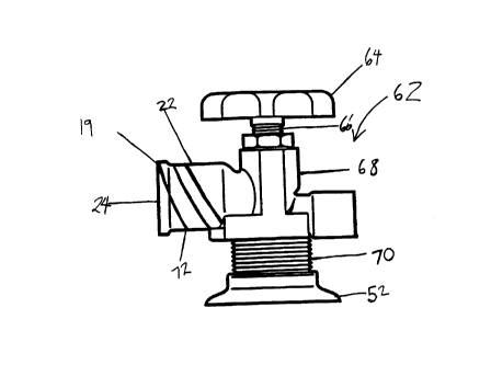
FIG. 2 illustrates generally a Type 1 pressurized gas tank valve unit 62 which
includes a turnwheel 64 for raising and lowering a stem 66 which opens and closes
a valve in housing 68. Threaded portion 70 threadably engages a source of
pressurized gas 52. Valve stem 22 includes an outer face 19 and an orifice 24 which
is in communication with the valve in housing 68. When valve unit 62 is, for
example, a Type 1 conne~tion valve unit, valve stem 22 includes external threads 72
and orifice 24 includes an additional safety valve mechanism, as illustrated anddescribed further below.
FIG. 3 illustrates a prior art pressurized gas tank valve plug 9 comprised of a
handle portion 10, a threaded shaft 11, and, optionally, a seal 12 en~aged on said
lhfeadad shaft 11. The plug is inserted within orifice 15 of, for example, valve stem
14 of a POL valve unit 42. Threaded shaft 11 is in threaded engagement with an
interior of sidewall 13 of, for eAd,nple, POL valve stem 14.
FIG. 4 illustrites a protective cap 20 in place over orifice 24 of, for example,valve stem 22 of a Type 1 connection valve unit 62. Cap 20 engages exterior
threads (as shown in FIG. 2) on valve stem 22. Backcheck valve module 21 is
seated in place in orifice 24 and in proximity to side wall 23 of Type 1 connection
valve stem 22.
~OE~3997~ ~
CA 02206910 1997-06-04
Express Mail No. TB756260703US
The pressurized gas tank valve plug of the present invention can seal two types
of pressurized gas tank valve, each of which contain a distinct type of valve stem,
without damaging any interior structure contained within an orifice of the valve stem.
The valve stems differ in an internal depth of the valve stem, one depth being
5 sh-"ower than the other. The internal depth of the valve stem can be measured from
an outer face of the valve stem to the lowest point within the orifice to which a valve
plug inse,led therein could travel to and just barely contact that point. For example,
Type 1 pressurized gas tank valve stem 22 has an interior depth of orifice 24
measured from the lowest point within the orifice which is the top of a device such
as backcheck valve module 21 within orifice 24 to the surface of outer face 19 of
valve stem 22. This internal depth is shallower than an internal depth of a POL
pressurized gas tank valve stem 14 measured from the lowest point of an inner
beveled base 16 to the surface of outer face 17. In a particular embodiment of the
invention, the Type 1 pressurized gas tank valve stem is part of a Type 1 connection
1 S valve unit, typically used with propane tanks and the POL pressurized gas tank valve
stem is part of a POL valve unit, typically used with propane tanks. The valve stem
of a Type 1 connection valve unit has an outside diameter across an outer face 19
of about 1 and 1/16 inches, and an inner diameter across outer face 19 of about
13/16 of an inch. The interior depth of a Type 1 conne~ion valve stem is about 9/16
20 of an inch when backcheck valve module 21 is seated at its deepesl depth within the
valve stem. The valve stem of a POL valve unit has an outside diamel~r across anouter face 17 of about 1 and 3/16 inches, and an inner diameter across outer face
17 of about 13/16 of an inch. The interior depth of a POL valve stem is about 15/16
of an inch measured from outer face 17 to the lowest point of the beveled portion of
25 the interior of the valve stem.
It is to be unde(slood that the invention is not limited to propane tank valves,- but includes any tank valves with similar configurations such that essentially the
same tank valve plug of the present invention could be utilized, and includes the
plugging of valves wherein the tank valve plug of the present invention could be30 utilized with .nodir.calions as could be made by one of ordinary skill in the art without
23997~ 1
CA 02206910 1997-06-04
Express Mail No. TB756260703US
undue experimentation. In that regard a ~Type 1 pressurized gas tank valve~ is an
example of ~a first pressurized gas tank valve~ and a ~POL pressurized gas tank
valve~ is an example of ~a second pressurized gas tank valve.~
FIG. 5 illustrates a particular embodiment of the present invention. Pressurizedgas tank valve plug 35 is co",~rised of a handle 30, a neck 31, a seal 32, a shaft 33,
and is secured within orifice 15 of valve stem 14. Pressurized gas tank valve plug 35
of the present invention is a device which is used to seal off an orifice of a valve
stem of a pressurized gas tank. The pressurized gas tank can contain various gases;
such as hydrocarbons and in particular propane.
Handle 30 is a device which allows a force, preferably a torque, to be imparted
to pressurized gas tank valve plug 35. The handle 30 is in force-transferable relalion
with the shaft 33 so that shaft 33 is in contact with handle 30 either directly or
indirectly, such that a force, particularly a torque, applied to handle 30 will result in
a force, such as a torque, applied to shaft 33. Handle 30 and shaft 33 can be
integral or sepalale and joined by, for exdlllrle~ a weld, an adhesive, a direct threaded
engagement, a screw, a bolt or some combination thereof. Handle 30 can be, but is
not limited to a spherical shape, a planar shape with any of a variety of perimeter
designs, and can be knurled, or smooth. Handle 30 can comprise a top and neck 31as in, for example, FIGS. 5 and 6, however, it is not limited to this particularconfiguration. Handle 30 can be integrally formed with other elements of plug 35such as shaft 33 or it can be fitted to such other elements, by, for example, chemical
means such as adhesives; "lecl-anic~! means such as screws, bolts, threaded shafts;
or it can be welded together. Handle 30 can be formed by milling, drop-forging,
stampul~, molding, die casting or other means as are known in the art.
Alle.. la~ ely, shaft 33 can be formed without an integral handle, rather shaft
33 can have a slot or an indeotalion which, for eAa",ple, can enga~e a tool which can
rotate shaft 33 such as a screw driver or an Allen wrench. Alternatively, shaft 33
can have a faceted upper portion which can engage, for example, a wrench.
Handle 30 can include a surface such as an underside of neck 31 suitable for
30 sea~7b'e engagement with a pressurized gas tank valve stem. The handle underside
~ff~\23997~ ~
CA 02206910 1997-06-04
Express Mail No. TB756260703US
surface is preferably smooth more preferably smooth and flat. Neck 31 can be
beveled to provide for sealing engagement with an interior surface of orifice 15 or 24
of pressurized gas valve stem 14 or 22. Neck 31 preferably has a diameter largerthan a J;a,-,eter of shaft 33. Neck 31 need not be integral with handle 30, it can be
integral with shaft 33. If neck 31 is not integral with handle 35 or shaft 33, that is
it is free to move relative to handle 30 or shaft 33, it would comprise a seal 32 as
described below. Rough, non-flat surfaces of handle 30, particularly the underside
of handle 30, can function in conjunction with suitably modified seals.
Shaft 33 is separately and preferably reversibly fittable within orifice 15 and
orifice 24 so that it can be inserted and removed from each orifice. Shaft 33 can be
reversibly fittable in all of the foregoing ways. Shaft 33 adjacent handle 30 ispreferably threaded, allowing for threading engagement with a threaded female
receptacle. In prefer,~d embodi",ents the thread is left-handed. However, shaft 33
can be only partially threaded, such that an upper portion of shaft 33 which canextend above the outer face 17 or 19 of valve stem 14 or 22 can be non-threaded.In allernali~e embodiments the entire shaft 33 can be non-ll~readed~ but can engage
the inner walls of valve stem 14 or 22 through friction or through, for example,spring loaded knobs which are pushed out from the surface of shaft 33 along somelength of shaft 33 and engage an interior wall of valve stem 14 or 22. Alternatively,
outer face 17 of valve stem 14 and outer face 19 of valve stem 22 can extend past
the outer walls of valve stem 14 and 22 and clamps can affix the plug 35 to valve
stem 14 or 22 thereto.
Shaft 33 can be in contact with handle 30 either directly or indirectly, such that
a tor~ applied to handle 30 will result in a torque applied to shaft 33. The handle
30 and shaft 33 can be integral or separate and joined by, for example, a weld, an
adhesive, a direct threaded engagement, a screw, a bolt or some combination
thereof.
That portion of shaft 33 of plug 35 which fits within orifice 15 of valve stem
14 and orifice 24 of valve stem 22 p~eferdbly has a length not excee~ ng that of an
internal depth of the shallower of two pressurized gas tank valve stem orifices as
~ff~3997~ 1
CA 02206910 1997-06-04
Express Mail No. TB756260703US
defined above. In Particular~ the portion of shaft 33 which fits within a valve stem
orifice from an end of shaft 33 opposite neck 31 has a length along a longitudinal
axis of shaft 33 from an undersurface of neck 31 to the end of shaft 33 which is less
than an interior depth of a Type 1 connection valve stem.
A portion of shaft 33 can extend above outer face 17 or outer face 19.
Accordingly, when shaft 33 is inserted to the maximum extent possible into a Type
1 connection valve stem, the base 36 of shaft 33 will not contact or will barelycontact, for example, the backcheck valve module 21, so that no damage is done
thereto, and/or the valve is not opened. To the extent that a seal 32 is inter~,osed
between the underside of handle 30 and an outer face 17 or 19 of pressurized gastank valve stem 14 or 22, and thereby elevates shaft 33, shaft 33 can be lengthened
so long as that portion of shaft 33 within the orifice will still not contact or will barely
contact the base of any device within the orifice of the valve such as a backcheck
valve module 21, so that no damage is done thereto and/or the valve is not opened.
Shaft 33 prefe.ably has a diameter at least partially sealingly engageable with
orifice 15 and orifice 24 of valve stem 14 and valve stem 22 such that shaft 33 is
not so large in dia---eter so as not to be able to functionally fit within orifice 15 and
orifice 24 of valve stem 14 and valve stem 22. Nor should the diameter be so small
so as to allow for a wobble of shaft 33 within valve orifice 15 and valve orifice 24.
That is, shaft 33 should ft securely, such that it can function to at least partially seal
the gas tank valve, so that no appre~ -~'e amount of gas escares and no appreciable
amount of debris can enter. Alternatively, shaft 33 need not appreciably seal gas in
and dirt out, if handle 30 and/or neck 31 and/or an additional seal perform these
fun.,~ns onli.ely.
In one embodiment, shaft 33 can include a pressure relief hole which allows any
gas which can have built up to vent out as plug 35 is removed from ocifice 15 or 24
of valve stem 14 or 22. The pressure relief hole should preferably allow venting to
occur while shaft 33 is still sufficiently engaged by, for example, threaded
engagement with valve stem 14 or 22, so that any gas pressure built up does not
30 blow the plug out of the orifice before venting can occur.
~UW' ._16~1115~3
CA 022069l0 1997-06-04
- 10 -
Express Mail No. TB756260703US
Seal 32 is preferably adjacent the handle 30. Seal 32 is preferably a
co~ ressible material which helps to prevent leakage of gas through valve stem 14
or 22. The co,--pressible material can be, for example, rubber, cork, synthetic
co,--posilas, soft metals, such as lead and the like as would known to one of ordinary
5 skill in the art. Seal 32 can be affixed to the underside of handle 30 by, for example
adhesives or by frictional forces or can be relatively loose and be held in place by its
interposition between handle 30 and valve outer face 17 or 19. Seal 32 can be
continuous, as for e,cd..-rle, a rubber 0-ring or d;scontinuous as in a string of material
which can be wrapped about the pressurized gas tank valve plug 35 at for example10 the juncture of handle 30 and shaft 33.
Seal 32 need not be in contact with handle 30, althou~h, in a prafe. ~ ~d
embodiment, seal 32 is interposed between an underside of handle 30 and an outerface 17 of, for example, a POL valve stem 14 or an outer face 19 of, for example,
a Type 1 conne-,lion valve stem 22. The placement of seal 32 in this location allows
15 for the sealing of, for exa..lr'e, both a Type 1 connection propane gas tank valve and
a POL valve. This is so because due to the backcheck valve module 21 used in, for
exa...~le, Type 1 conne~tion propane gas tank valve stems, a sealing engagement at
an inner beveled base of a valve stem as in, for example, a POL valve could not be
achieved. However, both, for example, POL valves and Type 1 connection valves
20 have a valve stem having an outer face suitable for se~lable engagement.
Less preferably, a sealing ~--a~erial can be affixed adjacent the bottom of
threaded shaft 33 of plug 35 so that when plug 35 is fit into orifice 15 of, forexamp~, a POL valve stem 14 it seals at the base of valve stem 14 and when fit into
orific~ 24 of a Typ~ 1 connection valve stem 22 it will not damage backcheck valve
25 modulo 21 or inadve-ler~ open the backcheck valve, because of the resiliency of
the sealing ...at~rial.
In an all~.--ali./e embodiment seal 32 can be located on the underside of handle30 and in sealing engage---ent with an interior surface of the wall of valve stem 14
or 22. In such an embodiment seal 32 can also be in contact with shaft 33. In a
30 prefer.dd embodiment seal 32 is a rubber 0-ring.
~UW~ 571115~
CA 022069l0 l997-06-04
Express Mail No. TB756260703US
Additionally, in other alternative embodiments seal 32 can be disposed
anywhere along the length of shaft 33, such that it is in sealin~ engagement
between shaft 33 and an interior surface of valve stem 14 or 22.
Seal 32 can, fot example, be held in place by friction or can be affixed by, foreA~,.nr'e, an adhesive. However, to the extent such placement can cause increased
friction in inserting the pressurized gas tank valve plug 35 and/or additionally can
increase the po~ ~ bi' t~ of da--,aging a seal so disposed, alternative placement can be
preferred.
A gap 34 exists between a lower face 36 of shaft 33 and inner beveled base
16 of valve stem 14 as shaft 33 is shorter than the prior art plug shaft 11. However,
a lower face of neck 31 and/or seal 32 provides for sealing engagement between
pressurized gas tank valve plug 35 and outer face 17 of POL style propane gas tank
valve stem 14.
FIG. 6 illustrates a particular embodiment of the present invention. Propane gastank valve plug 35 comprised of a handle 30, a neck 31, a seal 32, a shaft 33,
prefe...bly II--eaded, is secured within orifice 24 of, for example, valve stem 22 of a
Type 1 connection valve 62 unit. Pressurized gas tank valve plug 35 prefe...bly has
exterior threads (not shown) on valve stem 22. A gap 40 exists between the lowerface 36 of shaft 33 and backcheck valve module 21 as shaft 33 is shorter than prior
art shaft 11. Attempts to insert prior art gas tank valve plug 9 into orifice 24 of
valve stem 22, could damage, for example, the backcheck valve module 21 outer
seal or push backcheck valve module 21 into the open position, possibly resulting
in d-n5~a.rws leaks of possibly flammable pressurized gas.
While the descriplion above refers to particular embodiments of the present
invention, it will be understood that many modifications can be made without
departing from the-spi-it thereof. The accompanying claims are intended to coversuch modifications as would fall within the true scope and spirit of the presentinvention.
The presently disclosed embodiments are therefore to be considered in all
respect-c as illustrative and not restrictive, the scope of the invention being indicated
SMW' ._1571115~
CA 022069l0 l997-06-04
-12 -
Express Mail No. TB756260703US
by the appended claims, rather than the foregoing description, and all changes which
come within the meaning and range of equivalency of the claims are therefore
intended to be embraced therein.
~UW' - _1571115~3