Note : Les descriptions sont présentées dans la langue officielle dans laquelle elles ont été soumises.
CA 02207660 1997-06-12
WH-9770CA
TITLE: SCREW PIERCABLE STRUCTURAL SUPPORT FOR A PLANAR
SUBSTRATE
FIELD OF THE INVENTION
The present invention relates to a structural support designed to
secure and support a substrate used to form a wall or floor in a concrete
forming system.
BACKGROUND OF THE INVENTION
It is standard practice in concrete forming to secure a substrate by
means of a plurality of spaced apart fixed beams. These beams preferably
are of an extruded aluminum or an aluminum composite.
Each beam has a planar support for engaging the rear face of the
substrate. The substrate sits on one side of the support and screws are
passed from the other side at 90° through the support into the
substrate.
According to conventional practice, beams have a series of
punched holes spaced along the length of the beam. The series of holes
2 0 are provided as a second manufacturing step before the beams are sent to a
construction site. It is also known to drill the beam as required on the
construction site although this is not efficient.
The present invention addresses these problems and allows the
use of a metal piercing screw thereby avoiding a drilling or punching step.
Also the beam of the present invention can be manufactured at less cost
and has an improved delivery cycle that can be critical in the construction
industry. Self-drilling screws for metal are known which can be used with
conventional beams to avoid the drilling or punching steps.
3 0 Unfortunately, self-drilling screws have poor holding properties in the
substrate. This is very important as this property determines the
durability of the assembled beam and substrate.
SUMMARY OF THE INVENTION
3 5 The present invention provides a structural support for a planar
substrate which has been particularly adapted to overcome the drawbacks
noted above with respect to prior art beams. More particularly, the
-1-
CA 02207660 1997-06-12
WH-9770CA
structural support for a planar substrate of the present invention has a
platform one side of which is a substrate receiving face and the other side
of which is a screw mounting side provided with a screw channel near an
edge of the platform. The screw channel produces a thinning of the
platform and acts as a guide for the securing screws. The thinned
platform allows a metal piercing screw to be used, which screw has good
holding properties with the substrate For example, a wood screw can
pierce the thinned platform and provide a strong hold with the substrate.
According to an aspect of the invention, the screw channel is
angled to a position in which it is readily accessible without interference
from the base of the support and such that the securing screw has on
increased ability to hold the substrate.
BRIEF DESCRIPTION OF THE DRAWINGS
Preferred embodiments of the invention are shown in the
drawings, wherein:
Figure 1 is a perspective view of a section of a planar substrate
securing system according to a preferred embodiment of the present
2 0 invention;
Figure 2 is an end view showing one of the structural support
members from the system of Figure 1;
Figures 3 and 4 are end views of different structural supports
according to further preferred embodiments of the present invention.
DETAILED DESCRIPTION OF THE PREFERRED EMBODIMENTS
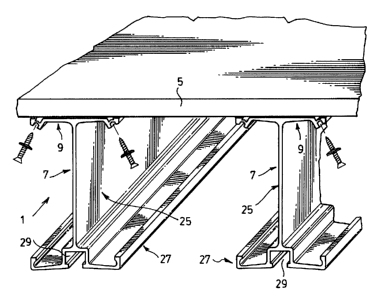
Figure 1 shows a structural support system generally indicated at
1 for supporting a planar substrate 5. This system can be used in a
horizontal position as shown in Figure 1 where the substrate is intended
3 0 to temporarily support a poured concrete floor or it can be used in a
vertical position to provide temporary support for a poured concrete wall.
The system relies on a plurality of structural supports generally
indicated at 7 having the substrate attached to one side of the supports.
In the preferred embodiment shown in Figures 1 and 2, each of
the structural supports 7 has an I-beam construction or a channel-like
-2-
CA 02207660 1997-06-12
WH-9770CA
construction. This construction includes a platform generally indicated at
9 at one side of the beam and a base generally indicated at 27 at the other
side of the beam. The platform and the base are secured to one another by
means of a main support web 25 at right angles to both the platform and
the base.
The base, as is known in the art, has an undercut channel 29 for
receiving a bolt head used to attach the base to the fixed support not
shown.
The key to the present invention resides in features provided at
the platform 9 of the structural support. In particular, the one side 11 of
the platform receives and supports the substrate 5 and the other side 12,
i.e. the side to which the web 25 is secured, is a screw mounting side of the
platform. Side 12 is provided with a screw channel 13 near each edge of
the platform. The substrate receiving face 11 of the platform is also
provided with a pair of channels 23 opposed to and separated from the
channels 13 by means of relatively thin webs 15 in the platform. The webs
divide the platform into a main platform region 17 on one side of each
2 0 web and an edge region 21 to the outside of each web. As will be clearly
seen in Figure 2, the edge region 21 is substantially more robust than the
web and provides reinforcement edgewise of the platform for the web 15.
Any impact on the edge region which might otherwise damage the web is
distributed by the edge region and avoids localized damage of the web.
Although two screw receiving channels are shown, the support can be
manufactured with a single channel, or three or more channels.
In the preferred embodiment as shown, structural support 7 is
extruded aluminum and substrate 5 is in the form of a piece of plywood
3 0 supported as shown in Figure 1 by a plurality of spaced apart structural
supports. The securing of the substrate to the platform 9 of the structural
support is provided by a series of screws such as wood screw 25 that pierces
through the aluminum into the substrate.
3 5 As is clearly shown in Figure 2, screws 25 are fitted into the screw
channels 13 where they pierce the webs 15 which are substantially thinner
than the rest of the platform. This allows for a much easier piercing of the
-3-
WH-9770CA
CA 02207660 1997-06-12
platform. In addition, the webs 15 are V-shaped coming to an apex for
seating the tip of the screw and further easing passage of the screw through
the web at the desired 45° angle.
As will be seen in the left hand side of Figure 2, the screw
produces burrs 24 in the aluminum where it passes through the web 15.
However, these burrs do not protrude above the flat substrate receiving
face of the platform but rather are maintained in the channels 23.
Furthermore, any burring which occurs on the screw mounting side of the
platform occurs within the channels 13 so that a used support beam made
in accordance with the present invention is much safer to handle than a
used prior art beam where burring of the aluminum material occurs on an
exposed surface where the beam might well be handled.
Another novel feature of the present invention is found in the
orientation or angling of the screw channels. As will be seen, the main
region 17 of the platform has an end portion 19 on one side of channel 13.
this end portion is set at an angle and preferably a 45° angle relative
to the
main region of the platform. The other side of the channel is bordered by
2 0 the robust edge region 21 which is also angled at the mouth of the
channel. The screw channel is therefore angled outwardly away from the
main web of the beam at 45° to the platform. This angle allows good
access for a power tool used to secure the screws.
The angling of the two channels as described immediately above,
produces a number of benefits. Firstly, it provides a very good working
tool angle at each channel. For example, when working with a power
screw driver for passing the screw through the beam platform, there is no
interference with the base or web of the beam. In addition, the angling
3 0 away from 90° allows greater screw penetration into and more
positive
securing of the substrate to the support platform.
Although the description above has been specific with respect to
the use of plywood as the substrate and wood piercing screws as the
3 5 fasteners it would be understood that other appropriate substrates and
screws could be used. For example, the substrate could be in the form of a
plastic substrate held by appropriate screws or fasteners.
-4-
CA 02207660 1997-06-12
WH-9770CA
Figure 3 shows a modified structural support generally indicated
at 35. This support, like support 7, has a platform 38 with angled screw
channels 37 to one side of the platform and separated from burr channels
39 on the other side of the platform by V-shaped webs 41. However, in
this case, support 35 is additionally provided at one of its reinforced edges
with a substrate edge guide 43 extending outwardly at 90° to the
substrate
receiving face of the platform. As will be understood, this particular
structural support is only used along an edge of the substrate to protect the
edge, whereas the structural supports 7 would be used away of the edges of
the substrate.
Figure 4 shows a further modified structural support generally
indicated at 45. This structural support has a platform 47, one edge of
which is provided with opposing screw and burr channels 49 and 51
respectively separated by a V-shaped web 53. The other side of the
platform is void of any screw and burr channels but is rather provided
with a substrate edge guide 55.
2 0 The structural support configuration shown in Figure 4 clearly
demonstrates that the securing of the substrate need occur at one side only
of the platform of the support. It also demonstrates that the support can be
provided with a different type of base such as support base 61 used to
secure the support to a different type of support member.
Although various preferred embodiments of the present
invention have been described in detail, it will be appreciated by those
skilled in the art, that variations may be made without departing from the
spirit of the invention or the scope of the appended claims.
-5-