Sélection de la langue

Search

Sommaire du brevet 2212997 

Énoncé de désistement de responsabilité concernant l'information provenant de tiers

Une partie des informations de ce site Web a été fournie par des sources externes. Le gouvernement du Canada n'assume aucune responsabilité concernant la précision, l'actualité ou la fiabilité des informations fournies par les sources externes. Les utilisateurs qui désirent employer cette information devraient consulter directement la source des informations. Le contenu fourni par les sources externes n'est pas assujetti aux exigences sur les langues officielles, la protection des renseignements personnels et l'accessibilité.

Disponibilité de l'Abrégé et des Revendications

L'apparition de différences dans le texte et l'image des Revendications et de l'Abrégé dépend du moment auquel le document est publié. Les textes des Revendications et de l'Abrégé sont affichés :

  • lorsque la demande peut être examinée par le public;
  • lorsque le brevet est émis (délivrance).
(12) Brevet: (11) CA 2212997
(54) Titre français: MACHINE D'ENTRETIEN DE VOIES FERREES AVEC EXCAVATRICE DE BALLAST DE VOIE FERREE
(54) Titre anglais: A TRACK MAINTENANCE MACHINE FOR EXCAVATING BALLAST BED MATERIAL
Statut: Réputé périmé
Données bibliographiques
(51) Classification internationale des brevets (CIB):
  • E01B 27/06 (2006.01)
  • E01B 27/04 (2006.01)
(72) Inventeurs :
  • THEURER, JOSEF (Autriche)
(73) Titulaires :
  • FRANZ PLASSER BAHNBAUMASCHINEN-INDUSTRIEGESELLSCHAFT M.B.H. (Autriche)
(71) Demandeurs :
  • FRANZ PLASSER BAHNBAUMASCHINEN-INDUSTRIEGESELLSCHAFT M.B.H. (Autriche)
(74) Agent: RICHES, MCKENZIE & HERBERT LLP
(74) Co-agent:
(45) Délivré: 2005-06-28
(22) Date de dépôt: 1997-08-13
(41) Mise à la disponibilité du public: 1998-02-14
Requête d'examen: 2001-10-30
Licence disponible: S.O.
(25) Langue des documents déposés: Anglais

Traité de coopération en matière de brevets (PCT): Non

(30) Données de priorité de la demande:
Numéro de la demande Pays / territoire Date
A 1469/96 Autriche 1996-08-14

Abrégés

Abrégé français

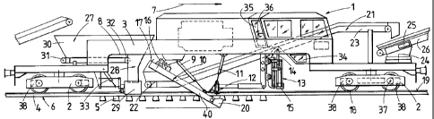
Machine d'entretien de voies (1) destinée à excaver de la matière d'encaissement d'une voie, ayant un châssis de machine (3) supporté sur des châssis porteurs sur voie (2) avec une portion évidée vers le haut (8). Associées au châssis de machine (3), par rapport à la direction de travail de la machine (1), se trouvent une unité de réception de ballast (27) avec une position de décharge de ballast (28), une chaîne excavatrice (10) verticalement réglable au moyen d'entraînements (9), une unité d'élévation de voie (12) et une unité convoyeuse (21) pour évacuer la matière de décaissement extraite par la chaîne excavatrice (10) dans la direction longitudinale de la machine. La chaîne excavatrice (10) avec son entraînement de chaîne (16) positionné dans la région d'extrémité supérieure ainsi qu'une unité de dégagement de ballast (13) avec un composant de dégagement de ballast (15) verticalement réglable et transversalement perpendiculaire à la direction longitudinale de la machine au moyen d'entraînements (14) sont agencés sous la portion évidée vers le haut (8) et l'unité d'élévation de voie (12) est agencée entre la chaîne excavatrice (10) et l'unité de dégagement de ballast (13). En outre, des glissières (29) désignées comme la position de décharge de ballast (28) sont prévues immédiatement après une extrémité d'admission (22) de l'unité convoyeuse (21) située sous la chaîne excavatrice (10).


Abrégé anglais

A track maintenance machine (1) for excavating ballast bed material of a track has a machine frame (3) supported on on-track undercarriages (2) with an upwardly recessed portion (8). Associated with the machine frame (3), with respect to the working direction of the machine (1), are a ballast receiving unit (27) with a ballast discharge position (28), an excavating chain (10) which is vertically adjustable by means of drives {9), a track lifting unit (12) and a conveyor unit (21) for removing the ballast bed material taken up by the excavating chain (10) in the longitudinal direction of the machine. The excavating chain (10) with its chain drive (16) positioned in the upper end region and also a ballast clearing unit (13) with a ballast clearing component (15) which is adjustable vertically and transversely perpendicularly to the longitudinal direction of the machine by means of drives (14) are arranged underneath the upwardly recessed portion (8) and the track lifting unit (12) is arranged between the excavating chain (10) and the ballast clearing unit (13). Furthermore, chutes (29) designed as a ballast discharge position (28) are provided immediately following an intake end (22) of the conveyor unit (21) located underneath the excavating chain (10).

Revendications

Note : Les revendications sont présentées dans la langue officielle dans laquelle elles ont été soumises.


7
Claims
1. A track maintenance machine (1) for excavating ballast
bed material of a track, comprising a machine frame (3)
supported on on-track undercarriages (2) and having an
upwardly recessed portion (B) with which there are associated,
with respect to the working direction of the machine (1), a
ballast receiving unit (27) with a ballast discharge position
(28), an excavating chain (10) which is vertically adjustable
by means of drives (9), a track lifting unit (12), an
operator's cab (35) and a conveyor unit (21) for removing the
ballast bed material taken up by the excavating chain (10) in
the longitudinal direction of the machine, characterised in
that the excavating chain (10) with its chain drive (16)
positioned in the upper end region and also a ballast clearing
unit (13) with a ballast clearing component (15) which is
adjustable vertically and transversely perpendicularly to the
longitudinal direction of the machine by means of drives (14)
are arranged underneath the upwardly recessed portion (8) and
the track lifting unit (12) is arranged between the excavating
chain (10) and the ballast clearing unit (13), and in that
chutes (29) designed as the ballast discharge position (28)
are arranged immediately following an intake end (22) of the
conveyor unit (21) located underneath the excavating chain
(lo).
2. A machine according to claim 1, characterised in that a
highest point (17) of the excavating chain (10) with respect
to the vertical is a maximum of two metres away in the
operating position thereof from a reference plane (19) formed
by wheel contact points (18) of the on-track undercarriages
(2).
3. A machine according to claim 2,
characterised in that the intake end (22) of the conveyor unit
(21) for removing the ballast bed material taken up by the


8
excavating chain (10) is arranged a maximum of one metre away
from the reference plane (19).
4. A machine according to any one of claims 1 to 3,
characterized in that the operator's cab (34) is located
immediately preceding the ballast clearing unit (13) in the
working direction.
5. A machine according to claim 4, characterised in that an
additional operator's cab (35) is provided immediately above
the ballast clearing unit (13).
6. A machine according to any one of claims 1 to 5,
characterised in that bogie undercarriages each having two
axles (37) are provided as the on-track undercarriages (2),
each axle (37) having its own motive drive (38) associated
therewith.
7. A machine according to any one of claims 1 to 6,
characterised in that the ballast receiving unit (27) designed
as a ballast store (30j with a floor conveyor belt (31) is
provided at the rear end of the machine frame (3) with respect
to the working direction of the machine (1), and chutes (29)
which are vertically adjustable by means of drives (33) are
associated with a discharge end (32) of the conveyor belt
(31).
8. A machine according to any one of claims 1 to 7,
characterised in that the conveyor unit (21) is composed of a
first conveyor belt (23) arranged above the ballast clearing
unit (13) and a second conveyor belt (26) mounted at the front
machine end with respect to the working direction for rotation
around a vertical axis (24) and displaceable by means of a
drive (25) relative to the machine frame (3) in the
longitudinal direction of the machine.

Description

Note : Les descriptions sont présentées dans la langue officielle dans laquelle elles ont été soumises.


CA 02212997 1997-08-13
A 96/01469
1
A TRACK MAINTENANCE MACHINE FOR EXCAVATING BALLAST BED MATERIAL
The invention relates to a track maintenance machine for
excavating ballast bed material of a track, comprising a
machine frame supported on on-track undercarriages and having
'_
an upwardly recessed portion with which there are associated,
with respect to the working direction of the machine, a
ballast receiving unit with a ballast discharge position, an
excavating chain which is vertically adjustable by means of
drives, a track lifting unit, an operator's cab and a conveyor
unit for removing the ballast bed material taken up by the
excavating chain in the longitudinal direction of the machine.
A track maintenance machine for cleaning the ballast bed
of a track is known through European Patent 0 663 472 A1 in
which the excavating chain which is guided around the machine
frame has a screening unit associated therewith. A ballast
receiving unit located in the rear end region enables ballast
kept available in a hopper wagon to be supplied along with the
cleaned ballast to create the new ballast bed. The excavating
chain is preceded by a vertically and transversely adjustable
suction pipe which is connected to a vacuum unit. This
enables ballast to be removed by suction before the excavating
chain is used to form a so-called ballast bed gap. This
recess is necessary for the insertion of a transverse chain
section of the excavating chain into the ballast bed
underneath the track.
Another track maintenance machine is known through US
Patent 5 257 580 and is used to excavate ballast bed material
in conjunction with the creation of a formation protection
layer. The appropriately large-sized excavating chain for a
high excavating performance is guided in its upper end region


CA 02212997 1997-08-13
2
around the machine frame, so that in this portion the said
machine frame has to have a reduced cross-section, with
consequently increased design effort. The ballast receiving
unit positioned in the rear end region enables new ballast to
be supplied continuously, while the fouled ballast is supplied
by the excavating chain and the conveyor unit to preceding
hopper wagons. The four-axle on-track undercarriage preceding
the excavating chain in the work ~n~ direction is designed so
as to be movable in the longitudinal direction of the machine
relative to the machine frame, so that the track can be lifted
to a suitable height for unimpeded use of the appropriately
large-sized excavating chain.
Finally, it is also known through US Patent 4 502 389 and
US Patent 4 357 874 to use an excavating chain in conjunction
with the section-by-section removal of a track panel in order
to remove the ballast bed. To do this, however, the machine
frame must accordingly be made longer than a track panel
section by appropriately spacing the on-track undercarriages
further apart.
The object of the present invention is to provide a track
maintenance machine of the type previously specified which is
particularly suitable for quick and efficient operational use
in shorter track sections.
This object is achieved according to the invention with a
track maintenance machine of the type described in the
introduction in that the excavating chain with its chain drive
positioned in the upper end region and also a ballast clearing
unit with a ballast clearing component which is adjustable
vertically and transversely perpendicularly to the
longitudinal direction of the machine by means of drives are
arranged underneath the upwardly recessed portion and the
track lifting unit is arranged between the excavating chain
and the ballast clearing unit, and in that chutes designed as
the ballast discharge position are arranged immediately


CA 02212997 2004-07-26
3
following an intake end of the conveyor unit located
underneath the excavating chain.
A machine equipped with these features can be produced
with a minimum of design effort and more particularly, can be
used efficiently in combination with the ballast clearing unit
even in short track possession times. A reduction in the
design effort is the result particularly of the simplified
design of the frame which has no need of a complicated
reduction in its cross-section for encirclement by the
excavating chain. The shortened chain length resulting from
the arrangement of the excavating chain underneath the machine
frame also produces a shorter conveying distance to the
discharge of the ballast bed material onto the conveyor unit.
A trench running transversely underneath the track for the
insertion therein of the excavating chain may be produced with
the ballast clearing unit in a particularly quick and
simplified manner. In addition, the arrangement of the
excavating chain and the ballast clearing unit underneath the
upwardly recessed portion of the machine frame ensures that
there is a particularly good view from the operator's cab.
Other advantages of the invention are evident from the
drawing.
The invention is described in more detail below with the
aid of an embodiment shown in the drawing, in which:
Fig. 1 shows a side view of the machine with an
excavating chain [and]1 a preceding ballast clearing
unit,
Fig. 2 shows an enlarged view of the ballast clearing
unit in the longitudinal direction of the machine, and
1 'On' in the original Austrian text.


CA 02212997 1997-08-13
4
Fig. 3 shows an enlarged detailed view of the excavating
chain.
The track maintenance machine 1 shown in simplified form
has a machine frame 3 supported on on-track undercarriages 2
and is designed to travel on a track 6 composed of rails 4 and
sleepers 5 in the working direction shown by an arrow 7.
Positioned in an upwardly recessed portion 8 of the
machine frame 3 located between the on-track undercarriages 2
are an excavating chain 10 which is vertically adjustable by
means of drives 9, a track lifting unit 12 which is vertically
adjustable by means of drives 11 and also a ballast clearing
unit 13. The said ballast clearing unit is equipped with
ballast clearing components 15 which are adjustable vertically
and perpendicularly to the longitudinal direction of the
machine by means of drives 14. Both the excavating chain 10
with its chain drive 16 positioned in the upper end region and
the ballast clearing unit 13 are positioned underneath the
upwardly recessed portion 8 of the machine frame 3. A highest
point 17 of the excavating chain 10 with respect to the
vertical is a maximum of two metres away in the operating
position thereof from a reference plane 19 formed by wheel
contact points 18 of the on-track undercarriages 2. This
results in a short conveying distance for the ballast bed
material from a cutter bar 20 forming the lowest portion and
extending perpendicularly to the track and the highest point
17.
A conveyor unit 21 extending in the longitudinal
direction of the machine is provided for removing the bedding
material or ballast taken up by the excavating chain 10. An
intake end 22 of the conveyor unit 21 located immediately
underneath the highest point 17 of the excavating chain 10 is
arranged a maximum of one metre away from the reference plane
19. The conveyor unit 21 is composed of a first conveyor belt
23 arranged above the ballast clearing unit 13 and a second


CA 02212997 1997-08-13
conveyor belt 26 mounted at the front machine end for rotation
around a vertical axis 24 and displaceable by means of a drive
25 relative to the machine frame 3 in the longitudinal
direction of the machine.
A ballast receiving unit 27 with a ballast discharge
position 28 is located in the rear end region of the machine
1. This discharge position is in',_the form of chutes 29,
spaced apart from each other perpendicularly to the
longitudinal direction of the machine and positioned
immediately above the sleepers 5. These chutes are positioned
immediately following the intake end 22 of the conveyor unit
21. The ballast receiving unit 27 has a ballast store 30 with
a floor conveyor belt 31 extending in the longitudinal
direction of the machine. The chutes 29 which are vertically
adjustable by means of drives 33 are associated with a
discharge end 32 of the conveyor belt 31.
Respective operator's cabs 34,35 with central control
units 36 are located immediately preceding and above the
ballast clearing unit 13. The on-track undercarriages 2 are
bogie undercarriages with two axles 37 respectively, each
having its own motive drive 38 associated therewith.
Respective hopper wagons (not shown or merely indicated) are
coupled to the front and the rear end of the machine 1, each
wagon having a floor- and a transfer conveyor belt.
As Fig. 2 shows, respective pairs of ballast clearing
components 15 located in the vicinity of half of the track are
mounted on a carrier frame 42 which is mounted for transverse
displacement on guide columns 43 extending horizontally and
perpendicularly to the longitudinal direction of the machine.
Each outer clearing component 15 located further away from the
track centre is mounted on the carrier frame 42 so as to pivot
around an axis 44 extending in the longitudinal direction of
the machine, and with the aid of a drive 45 may be pivoted
from a position shown in vertical lines into a position shown


CA 02212997 1997-08-13
6
in dot and dash lines. The ballast can thereby be moved into
the outer shoulder region of the ballast bed. Each carrier
frame 42 is adjustable vertically with the aid of the vertical
drives 14 via vertical guide columns 46.
Using the total of four ballast clearing components 15 of
the ballast clearing unit 13 which are spaced apart from one
another in the transverse directQn of the machine, a trench
39 shown in dot and dash lines may be made in the ballast bed
by moving the ballast to the side towards the ballast bed
shoulder. The cutter bar 20 of the excavating chain 10 may
easily be inserted into this trench 39 underneath the track 6.
The machine 1 is then moved until both longitudinal parts 40
of the excavating chain 10 can be joined to the cutter bar 20
with the aid of a quick-action fastening 41 (see Fig. 3).
The quick-action fastening 41 of the excavating chain 10
shown in Fig. 3 is a hydraulic cylinder 47 which is secured to
the longitudinal part 40 of the excavating chain 10. A flange
48 fixed to the cutter bar 20 may be connected to a piston rod
of the hydraulic cylinder 47 by way of a bolt 49.

Dessin représentatif
Une figure unique qui représente un dessin illustrant l'invention.
États administratifs

Pour une meilleure compréhension de l'état de la demande ou brevet qui figure sur cette page, la rubrique Mise en garde , et les descriptions de Brevet , États administratifs , Taxes périodiques et Historique des paiements devraient être consultées.

États administratifs

Titre Date
Date de délivrance prévu 2005-06-28
(22) Dépôt 1997-08-13
(41) Mise à la disponibilité du public 1998-02-14
Requête d'examen 2001-10-30
(45) Délivré 2005-06-28
Réputé périmé 2015-08-13

Historique d'abandonnement

Il n'y a pas d'historique d'abandonnement

Historique des paiements

Type de taxes Anniversaire Échéance Montant payé Date payée
Enregistrement de documents 100,00 $ 1997-08-13
Le dépôt d'une demande de brevet 300,00 $ 1997-08-13
Taxe de maintien en état - Demande - nouvelle loi 2 1999-08-13 100,00 $ 1999-07-20
Taxe de maintien en état - Demande - nouvelle loi 3 2000-08-14 100,00 $ 2000-07-25
Taxe de maintien en état - Demande - nouvelle loi 4 2001-08-13 100,00 $ 2001-07-24
Requête d'examen 400,00 $ 2001-10-30
Taxe de maintien en état - Demande - nouvelle loi 5 2002-08-13 150,00 $ 2002-06-03
Taxe de maintien en état - Demande - nouvelle loi 6 2003-08-13 150,00 $ 2003-06-10
Taxe de maintien en état - Demande - nouvelle loi 7 2004-08-13 200,00 $ 2004-06-15
Taxe finale 300,00 $ 2005-04-13
Taxe de maintien en état - brevet - nouvelle loi 8 2005-08-15 200,00 $ 2005-06-16
Taxe de maintien en état - brevet - nouvelle loi 9 2006-08-14 200,00 $ 2006-06-27
Taxe de maintien en état - brevet - nouvelle loi 10 2007-08-13 250,00 $ 2007-06-22
Taxe de maintien en état - brevet - nouvelle loi 11 2008-08-13 250,00 $ 2008-06-25
Taxe de maintien en état - brevet - nouvelle loi 12 2009-08-13 250,00 $ 2009-06-25
Taxe de maintien en état - brevet - nouvelle loi 13 2010-08-13 250,00 $ 2010-06-25
Taxe de maintien en état - brevet - nouvelle loi 14 2011-08-15 250,00 $ 2011-06-27
Taxe de maintien en état - brevet - nouvelle loi 15 2012-08-13 450,00 $ 2012-06-27
Taxe de maintien en état - brevet - nouvelle loi 16 2013-08-13 450,00 $ 2013-06-27
Titulaires au dossier

Les titulaires actuels et antérieures au dossier sont affichés en ordre alphabétique.

Titulaires actuels au dossier
FRANZ PLASSER BAHNBAUMASCHINEN-INDUSTRIEGESELLSCHAFT M.B.H.
Titulaires antérieures au dossier
THEURER, JOSEF
Les propriétaires antérieurs qui ne figurent pas dans la liste des « Propriétaires au dossier » apparaîtront dans d'autres documents au dossier.
Documents

Pour visionner les fichiers sélectionnés, entrer le code reCAPTCHA :


Pour visualiser une image, cliquer sur un lien dans la colonne description du document. Pour télécharger l'image (les images), cliquer l'une ou plusieurs cases à cocher dans la première colonne et ensuite cliquer sur le bouton "Télécharger sélection en format PDF (archive Zip)" ou le bouton "Télécharger sélection (en un fichier PDF fusionné)".

Liste des documents de brevet publiés et non publiés sur la BDBC .

Si vous avez des difficultés à accéder au contenu, veuillez communiquer avec le Centre de services à la clientèle au 1-866-997-1936, ou envoyer un courriel au Centre de service à la clientèle de l'OPIC.


Description du
Document 
Date
(yyyy-mm-dd) 
Nombre de pages   Taille de l'image (Ko) 
Dessins représentatifs 1998-03-05 1 14
Abrégé 1997-08-13 1 32
Description 1997-08-13 6 249
Revendications 1997-08-13 2 81
Dessins 1997-08-13 1 41
Page couverture 1998-03-05 1 76
Description 2004-07-26 6 247
Revendications 2004-07-26 2 77
Page couverture 2005-06-01 1 54
Dessins représentatifs 2005-06-01 1 14
Taxes 2001-07-24 1 38
Cession 1997-08-13 4 126
Poursuite-Amendment 2001-10-30 1 34
Taxes 2003-06-10 1 35
Taxes 2002-06-03 1 35
Poursuite-Amendment 2004-02-18 2 40
Taxes 2004-06-15 1 42
Poursuite-Amendment 2004-07-26 6 187
Correspondance 2004-07-26 3 72
Correspondance 2005-04-13 1 36
Taxes 2005-06-16 1 36