Sélection de la langue

Search

Sommaire du brevet 2213300 

Énoncé de désistement de responsabilité concernant l'information provenant de tiers

Une partie des informations de ce site Web a été fournie par des sources externes. Le gouvernement du Canada n'assume aucune responsabilité concernant la précision, l'actualité ou la fiabilité des informations fournies par les sources externes. Les utilisateurs qui désirent employer cette information devraient consulter directement la source des informations. Le contenu fourni par les sources externes n'est pas assujetti aux exigences sur les langues officielles, la protection des renseignements personnels et l'accessibilité.

Disponibilité de l'Abrégé et des Revendications

L'apparition de différences dans le texte et l'image des Revendications et de l'Abrégé dépend du moment auquel le document est publié. Les textes des Revendications et de l'Abrégé sont affichés :

  • lorsque la demande peut être examinée par le public;
  • lorsque le brevet est émis (délivrance).
(12) Brevet: (11) CA 2213300
(54) Titre français: BICYCLETTE PLIANTE
(54) Titre anglais: COLLAPSIBLE BICYCLE
Statut: Réputé périmé
Données bibliographiques
(51) Classification internationale des brevets (CIB):
  • B62K 15/00 (2006.01)
(72) Inventeurs :
  • WANG, PING-TIEN (Taïwan, Province de Chine)
(73) Titulaires :
  • WANG, PING-TIEN (Taïwan, Province de Chine)
(71) Demandeurs :
  • WANG, PING-TIEN (Taïwan, Province de Chine)
(74) Agent: BULL, HOUSSER & TUPPER LLP
(74) Co-agent:
(45) Délivré: 2002-10-15
(22) Date de dépôt: 1997-08-18
(41) Mise à la disponibilité du public: 1999-02-18
Requête d'examen: 1999-02-10
Licence disponible: S.O.
(25) Langue des documents déposés: Anglais

Traité de coopération en matière de brevets (PCT): Non

(30) Données de priorité de la demande: S.O.

Abrégés

Abrégé français

Bicyclette pliante comprenant un cadre comportant une roue avant pivotante montée sur une première partie d'extrémité, et un tube de selle fixé sur une deuxième partie d'extrémité. Un cadre arrière comprend un tube vertical situé sous le tube de selle, une paire de haubans, chacun se prolongeant du tube vertical, une roue arrière pivotante montée entre la paire de haubans, et une paire de fixations de support ayant chacune une première partie d'extrémité fixée à un hauban correspondant de la paire de haubans et une deuxième partie d'extrémité située dans une position alignée à la roue arrière. Un mécanisme d'articulation est relié de façon articulée entre le tube de selle et le tube vertical de manière à permettre au tube vertical d'être articulé en fonction du tube de selle, ce qui fait tourner le cadre arrière vers la roue avant du cadre dans une position où la deuxième partie d'extrémité de chacune des deux fixations de support de même que la roue arrière peuvent être supportés sur le sol de façon synchrone.


Abrégé anglais


A collapsible bicycle includes a body frame including a
front wheel rotatably mounted on a first end portion
thereof, and a seat tube fixedly mounted on a second end
portion thereof. A rear frame includes an upright tube
disposed beneath the seat tube, a pair of seat stays each
extending from the upright tube, a rear wheel rotatably
mounted between the pair of seat stays, and a pair of
supporting brackets each having a first end portion fixedly
mounted on a corresponding one of the pair of seat stays and
a second end portion located at a position flush with the
rear wheel. A pivot mechanism is pivotally connected between
the seat tube and the upright tube such that the upright
tube can be pivoted relative to the seat tube, thereby
pivoting the rear frame toward the front wheel of the body
frame to a position where the second end portion of each of
the two supporting brackets together with the rear wheel can
be supported on the ground synchronously.

Revendications

Note : Les revendications sont présentées dans la langue officielle dans laquelle elles ont été soumises.


-6-
The embodiment of the invention in which an exclusive
property or privilege is claimed are defined as follows:

1. A collapsible bicycle comprising:
a body frame (10) including a first end portion
and a second end portion, a front wheel (14) rotatably
mounted on said first end portion of said body frame (10),
and a seat tube (15) fixedly mounted on said second end
portion of said body frame (10);
a rear frame (30) including an upright tube (31)
disposed beneath said seat tube (15), a pair of seat stays
(32) each extending from said upright tube (31), a rear
wheel (36) rotatably mounted between said pair of seat stays
(32), and a pair of supporting brackets (34) each having a
first end portion fixedly mounted on a corresponding one of
said pair of seat stays (32) and a second end portion (341)
located at a position flush with said rear wheel (36); and
a pivot mechanism (20) pivotally connected between
said seat tube (15) and said upright tube (31) such that
said upright tube (31) can be pivoted relative to said seat
tube (15), thereby pivoting said rear frame (30) toward said
front wheel (14) of said body frame (10) to a position where
said second end portion (341) of each of said two supporting
brackets (34) together with said rear wheel (36) can be
supported on the ground synchronously.
2. The collapsible bicycle in accordance with claim
1, wherein said pivot mechanism (20) includes an upper pivot
base (21) fixedly mounted on a lower portion of said seat
tube (15), and a lower pivot base (22) fixedly mounted on an


-7-
upper portion of said upright tube (31) and pivotally
connected with said upper pivot base (21).
3. The collapsible bicycle in accordance with claim
2, wherein said upper pivot base (21) is substantially
inverted U-shaped with two vertical pieces (211) each having
a first end portion (212) transversely defining a bore (214)
therein, said lower pivot base (22) pivotally fitted between
said two vertical pieces (211) and including a first end
portion (221) transversely defining a hole (222) therein and
aligning with said bore (214) of each of said two vertical
pieces (211), and a pivot axle (23) extending through said
bore (214) of each of said two vertical pieces (211) and
said hole (222) of said lower pivot base (22) such that said
lower pivot base (22) can be pivoted relative to said upper
pivot base (21).


Description

Note : Les descriptions sont présentées dans la langue officielle dans laquelle elles ont été soumises.

CA 02213300 1997-08-18

--2
1COL~APSIBLE BICYCLE
2FIELD OF THE INVENTION
3The present invention relates to a collapsible bicycle.
4BACKGROUND OF THE INVENTION
5A conventional collapsible bicycle generally includes a
6comp~icated structure such that it is not easy to ~old the
7collapsible, thereby causing an inconvenience in operation.
8In addition, the conventional collapsible bicycle needs
9to be provided with a kickstand with a foot post for
10supporting the bicycle. However, the total weight of the
11bicycle is concentrated on a ~ront part thereo~ when it is
12folded, thereby greatly increasing the force exerted on the
13~oot post such that the foot post possibly cannot be used to
1~support the folded bicycle stably
15The present invention has arisen to mitigate and/or
16o~viate the disadvantages of the conventional collapsible
17bicycle
I8SUMM~RY OF T~E INVENTION
19In accordance with one aspect of the present invention,
20there is provided a collapsible bicycle comprising a body
21frame including a first end portion-and a second end
22portion, a front wheel rotatably mounted on the first end
23portion o~ the body frame, and a seat tube ~ixedly mounted
24on the second end portion of the body frame.
25A rear frame includes an upright tube disposed beneath
26the seat tube, a pair of seat stays each extending rearward
27from the upright tube,: a rear wheel rotatably mounted
28between the pair of seat stays, and a pair o~ supporting
29

CA 022l3300 l997-08-l8


1 brackets each having a ~irst end portion fixedly mounted on
2 a corresponding one o~ the pair o~ seat stays and a second
3 end portion located at a position flush with the rear wheel.
4 A pivot mechanism is pivotally connected between the
seat tube and the upright tube such that the upright tube
6 can be pivoted relative to the seat tube, thereby pivoting
7 the rear ~rame toward the ~ront wheel of the body frame to a
8 position where the second end portion o~ each of the two
9 supporting brackets together with the rear wheel can be
supported on the ground synchronously.
11 Further ~eatures of the present invention will become
12 apparent after a careful reading of the detailed description
13 with appropriate re~erence to the accompanying drawings.
14 BRIEF DESCRIPTION OF THE DRAWINGS
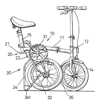
Fig. 1 is a front plan view of a collapsible bicycle in
16 accordance with the present invention;
17 Fig. 2 is a perspective view of a pivot mechanism o~
18 the collapsible bicyclei
19 Fig. 3 is an exploded view of Fig. 2;
Fig. 4 iS a front plan partially cross-sectional view
21 of Fig. 2;
22 Fig. S is an operational view of Fig. 4;
23 Fig. 6 is an enlarged ~ront plan view showing a rear
24 frame being disposed in a ~olded statusi and
Fig. 7 is a front plan view showing the collapsible
26 bicycle of Fig. 1 being disposed in a ~olded status.
27 DET~Tr.~n DESCRIPTION OF THE PREFERRED EMBODIMENTS
2~ Referring to Figs. 1-3, a collapsible bicycle according
29

CA 02213300 1997-08-18

--4--
1 to the present invention comprises a body frame 10 including
2 a top tube ll having a first end portion connected with a
3 head tube 12 and a second end portion connected with a seat
4 tube 15, and a front wheel 14 rotatably disposed under the
head tube 12.
6 A rear frame 30 includes an upright tube 31 disposed
7 beneath the seat tube 15, a pair of seat stays 32 each
8 extending rearward ~rom the upright tube 31, a rear wheel 36
9 rotatably mounted between the pair of seat stays 32, and a
pair of supporting brackets 34 each having a first end
ll portion mounted on a first end portion of a corresponding
12 one of the pair of seat stays 32 and a second end portion
13 341 located at a position flush with the rear wheel 36, and
14 an extension 35 extending from the second end portion 341 to
15 ....... be connected with a second end portion of the seat stay 32
16 A pivot mechanism 20 is pivotally connected between the
17 seat tube 15 and the upright tube 31 such that the upright
18 tube 31 can be pivoted relative to the seat tube 15
19 The pivot mechanism 20 includes an upper pivot base 21
~ixedly mounted on a lower portion of the seat tube 15, and
21 a lower pivot base 22 fixedly mounted on an upper portion of
22 the upright tube 31 and pivotally connected with the upper
23 pivot base 21.
24 The upper pivot base 21 is substantlally inverted U-
shaped with two vertical pieces 211 each having a first end
26 portion formed with an ear 212 transversely defining a bore
27 214 therein.
28 The lower pivot base 22 is-pivotally fitted between the
29

CA 02213300 1997-08-18

_5 _
1 two vertical pieces 211 and includes a first end portion
2 formed with a tubular rib 221 ~itted between the two ears
3 212 and transversely defining a hole 222 therein which
4 aligns with the bore 214 of each of the two ears 212.
S A pivot axle 23 extends through the bore 214 of each of
6 the two ears 212 and the hole 222 of the tubular rib 221 and
7 is engaged with a retaining nut 24 such that the lower pivot
8 base 22 can be pivoted relative to the upper pivot base 21.
9 In operation, referring to Figs 4-7 with re~erence to
1~ Fig 1, the upright tube 31 can be pivoted relative to the
11 seat tube 15 by means of the pivot mechanism 20, thereby
12 pivoting the rear frame 30 toward the front wheel 14 of the
13 body ~rame 10 ~rom a ~irst position as shown in Fig. 4 to a
14 - second position as shown in Figs. 5 and 6 where the second
end portion 341 of each o~ the two supporting brackets 34
16 together with the rear wheel 36 can be stably supported on
17 the ground synchronously, thereby easily ~olding the rear
18 frame 30 as shown in Fig. 7.
19 Accordingly, by such an arrangement, the rear frame 30
can be easily folded such that the space occupied by the
21 collapsible bicycle can be efficiently decreased.
22 ~ It should be clear to those skilled in the art that
23 further embodiments of the present invention may be made
24 without departing from the scope and spirit of the present
invention.
26
27
28
29

Dessin représentatif
Une figure unique qui représente un dessin illustrant l'invention.
États administratifs

Pour une meilleure compréhension de l'état de la demande ou brevet qui figure sur cette page, la rubrique Mise en garde , et les descriptions de Brevet , États administratifs , Taxes périodiques et Historique des paiements devraient être consultées.

États administratifs

Titre Date
Date de délivrance prévu 2002-10-15
(22) Dépôt 1997-08-18
Requête d'examen 1999-02-10
(41) Mise à la disponibilité du public 1999-02-18
(45) Délivré 2002-10-15
Réputé périmé 2007-08-20

Historique d'abandonnement

Il n'y a pas d'historique d'abandonnement

Historique des paiements

Type de taxes Anniversaire Échéance Montant payé Date payée
Le dépôt d'une demande de brevet 150,00 $ 1997-08-18
Requête d'examen 200,00 $ 1999-02-10
Taxe de maintien en état - Demande - nouvelle loi 2 1999-08-18 50,00 $ 1999-08-04
Taxe de maintien en état - Demande - nouvelle loi 3 2000-08-18 50,00 $ 2000-08-10
Taxe de maintien en état - Demande - nouvelle loi 4 2001-08-20 50,00 $ 2001-08-09
Taxe finale 150,00 $ 2002-07-25
Taxe de maintien en état - Demande - nouvelle loi 5 2002-08-19 75,00 $ 2002-07-25
Taxe de maintien en état - brevet - nouvelle loi 6 2003-08-18 75,00 $ 2003-07-29
Taxe de maintien en état - brevet - nouvelle loi 7 2004-08-18 300,00 $ 2004-09-10
Taxe de maintien en état - brevet - nouvelle loi 8 2005-08-18 100,00 $ 2005-07-22
Titulaires au dossier

Les titulaires actuels et antérieures au dossier sont affichés en ordre alphabétique.

Titulaires actuels au dossier
WANG, PING-TIEN
Titulaires antérieures au dossier
S.O.
Les propriétaires antérieurs qui ne figurent pas dans la liste des « Propriétaires au dossier » apparaîtront dans d'autres documents au dossier.
Documents

Pour visionner les fichiers sélectionnés, entrer le code reCAPTCHA :


Pour visualiser une image, cliquer sur un lien dans la colonne description du document. Pour télécharger l'image (les images), cliquer l'une ou plusieurs cases à cocher dans la première colonne et ensuite cliquer sur le bouton "Télécharger sélection en format PDF (archive Zip)" ou le bouton "Télécharger sélection (en un fichier PDF fusionné)".

Liste des documents de brevet publiés et non publiés sur la BDBC .

Si vous avez des difficultés à accéder au contenu, veuillez communiquer avec le Centre de services à la clientèle au 1-866-997-1936, ou envoyer un courriel au Centre de service à la clientèle de l'OPIC.


Description du
Document 
Date
(yyyy-mm-dd) 
Nombre de pages   Taille de l'image (Ko) 
Abrégé 1997-08-18 1 30
Description 1997-08-18 4 160
Revendications 1997-08-18 2 68
Dessins 1997-08-18 7 127
Page couverture 1999-03-15 1 60
Dessins représentatifs 1999-03-15 1 14
Page couverture 2002-09-10 1 48
Dessins représentatifs 2002-09-10 1 20
Taxes 2003-07-29 1 32
Taxes 2000-08-10 1 34
Correspondance 2004-09-24 2 54
Taxes 2004-09-10 1 31
Taxes 1999-08-04 1 34
Cession 1997-08-18 5 108
Correspondance 2002-07-25 1 35
Taxes 2001-08-09 1 35
Taxes 2002-07-25 1 33
Poursuite-Amendment 1999-02-10 2 105
Taxes 2005-07-22 1 24