Note : Les descriptions sont présentées dans la langue officielle dans laquelle elles ont été soumises.
CA 02213887 1997-08-26
DOCKET: 1833 Canada
SURGICAL CLIP
BACKGROUND
1. Technical Field
This disclosure relates generally to surgical clips
and, more particularly, to a surgical clip having
advantageous closure characteristics.
2. Background of Related Art
Ligation or occlusion of veins, arteries or blood
vessels has been a necessary part of surgical procedures
for many years. Typically, a severed blood vessel
requires closure on both sides of a severance site before
actual cutting takes place. In the past, surgeons used
thread or suture material to tie a blood vessel prior to
severing the vessel. This procedure was often time-
consuming and requires dexterity on the part of the
surgeon to properly close the vessel. In many instances,
the assistance of a nurse of attending surgeon was
necessary to perform this procedure.
The advent of surgical clips and clip appliers has
greatly enhanced the art of vessel occlusion. Surgical
clips are now commonly used for vessel ligation and
occlusion. Examples of surgical hemostatic clips are
described in U.S. Patent Nos. 5,171,253; 5,171,252;
5,100,420; 5,084,057; 4,971,198; 4,844,066; 4,799,481;
4,702,247; 4,414,721; 4,188,953; 4,146,130; 3,867,944 and
3,363,628.
Many factors impact upon the design of a surgical
hemostatic clip. For example, it is generally important
that the clip does not slip or become dislodged from a
blood vessel after it has been applied, at least during
an initial period of time.
CA 02213887 1997-08-26
-2
Surgical hemostatic clips should fully and
completely close about the vein, artery, or blood vessel
to which they are applied without undesirable gaps to
insure that the blood flow through the lumen of the
vessel is completely occluded.
Also, clip legs should not shift laterally with
respect to each other during closure. In the industry,
legs that have shifted a relatively small amount are said
to have "twisted". If the misalignment is relatively
large, the industry generally refers to such clip as
having "scissored". Clip legs can also shift
longitudinally with respect to each other. Scissoring or
twisting of a clip may result in damage to tissue and
enlargement of the gap between the clip legs while
longitudinal misalignment generally affects only the gap.
Generally, surgical hemostatic clips are U-shaped or
V-shaped in configuration and define a pair of legs
joined at one end by an apex or crown and spaced apart at
the opposed ends to define an opening therebetween.
Clips often have a bail portion, which is the arcuate or
V-shaped back portion, and substantially parallel legs
extending from the bail portion. The inside surfaces of
the clip legs may be constructed in a manner to improve
the occluding functions of the clip as well as to
restrict longitudinal and transverse dislocation of the
clip after it has been applied to the target blood
vessel. An example of a clip'having surface features is
described in U.S. Patent No. 4,976,722 which issued to
Failla.
Another factor in the design of surgical hemostatic
clips relates to its storage and advancement through a
clip applying instrument designed to apply multiple
clips. In certain commercially available clip appliers,
the surgical clips are stored in a linear array extending
CA 02213887 1997-08-26
-3-
longitudinally along the instrument with the legs of one
clip contacting the bail portion of the preceding clip.
As each clip is applied, the entire row of clips is
advanced such that the distal-most clip is positioned
within the jaws or in the on-deck position. Thus, the
shape, size and overall geometry of a surgical clip can
affect its movement through the clip applying apparatus.
Referring now to Figs. 3, 4, 4A and 4B, a prior art
type surgical clip is illustrated. Prior art clip 1
includes a bail portion 3 having angled back portions 3a
and 3b connected to each other at apex 2. Apex 2 is
characterized by angle "a". The bail portion is
demarcated by bend regions 6 and 7, wherein back portions
3a and 3b are connected to legs 4 and 5. Legs 4 and 5
are rectilinear and initially parallel to each other.
They terminate at distal ends 4a and 5a, respectively.
Referring to Fig. 4, clip 1 has an overall length L
defined by the distance between the distal ends 4a and
5a, and the outer edge of apex 2. Clip 1 has a width W
defined by the distance between the outer surfaces of the
legs 4 and 5. Legs 4 and 5 have a length "A" defined by
the distance between the distal ends 4a and 5a and the
bend regions 6 and 7.
The prior art clip illustrated herein is
characterized by a width (W) to total length (L) ratio
(W/L) of about 0.72. The ratio of leg length (A) to
total length (L) (A/L) is about 0.74. Angle "a" is about
125°. Prior art clip 1 has good characteristics for
movement through a prior art clip applier and
satisfactory closure characteristics. Nonetheless, room
for development of an optimized surgical clip exists
CA 02213887 1997-08-26
-4-
SUMMARY OF THE INVENTION
A surgical clip is provided herein which has
improved closure characteristics while retaining good
facility to move through a clip applier track without
jamming. The surgical clip includes (a) a bail portion
having first and second linear, and preferably arcuate,
back portions joined to each other at an apex, wherein
each of the first and second back portions has an
exterior surface and an interior surface; and (b) first
and second rectilinear legs, each leg having a distal
free end and an interior tissue contacting surface and an
exterior surface for receiving a compressive force, each
leg being joined to a respective one of the first and
second back portions and moveable in response to an
externally applied compressive force from an initial
spaced apart, open configuration to a closed
configuration, wherein the first and second legs are in
close proximity to each other. The legs are preferably
initially substantially parallel to each other and remain
substantially parallel to each other when moved from the
open configuration to the closed configuration.
Preferably, the exterior surface of the second back
portion includes an elongated ridge extending along the
linear orientation of the second back portion.
Dimensionally, the ratio of the overall clip width
to the overall clip length preferably ranges from about
0.68 to about 0.64, and the ratio of the length of the
legs to the total length of the clip ranges from about
0.36 to about 0.33, the legs being of preferably equal
length. The apex is preferably characterized by an angle
of less than about 100°.
The interior surface of the first back portion
preferably includes an elongated ridge extending along
the linear orientation of the first back portion, and the
interior surface of the second back portion preferably
CA 02213887 1997-08-26
-5-
includes a corresponding recess for receiving the
elongated ridge of the first back portion upon movement
of the clip legs from the open to the closed position.
Also, the interior surface of the second clip leg
preferably includes an interlock protrusion and the
interior surface of the first leg includes a
corresponding recess for receiving the interlock
protrusion of the second leg upon movement of the first
and second legs from the open position to the closed
position.
BRIEF DESCRIPTION OF THE DRAWINGS
Various embodiments are described herein below with
reference to the drawings, wherein:
Fig. 1 is a perspective view of one embodiment of an
advantageous surgical clip;
Fig. 2 is a top plan view of the embodiment of Fig.
1;
Fig. 2A is a detailed sectional view of a clip leg:
Fig. 3 is a perspective view of a prior art surgical
clip;
Fig. 4 is a top plan view of the prior art surgical
clip of Fig. 3 during closure of the clip;
Fig. 4A is a top plan view of a prior art clip
applier jaw holding and closing the prior art surgical
clip of Fig. 3;
Fig. 4B is a view similar to Fig. 4A showing further
closure of the prior art surgical clip;
Fig. 5 is a top plan view of a prior art clip
applier jaw holding the surgical clip of Fig. 1 prior to
closure;
Fig. 6 is an enlarged view of the distal end of the
prior art jaw of Fig. 5 showing initial closure of the
surgical clip;
Fig. 7 is a view similar to Fig. 6 showing partial
closure of the surgical clip;
CA 02213887 2005-02-08
-6-
Fig. 8 is a view similar to Fig. 7 showing complete
closure of the surgical clip of Fig. 1;
Fig. 9 is a top plan view of a plurality of surgical
clips of Fig. 1 positioned in series array in a surgical
clip magazine;
Fig. 10 is a perspective view of the surgical clip
magazine containing a series of surgical clips of Fig. 1;
Fig. 11 is a top plan view of an alternate
embodiment of an advantageous surgical clip: and
Fig. 12 is a perspective view of the alternate
embodiment of Fig. 11.
DETAILED DEBCRIPTION OF PREFERRED EMBODIMENTS
The disclosed embodiments of the advantageous
surgical clip are designed to be applied to body tissue
by a surgical clip applying apparatus. A surgical clip
applying apparatus generally has a pair of jaws to
position the clip relative to tissue and to deform or
close the clip about tissue, usually by bending the clip
near its apex such that the legs of the clip close about
the tissue, such as, for example, a blood vessel.
Suitable surgical instruments for use in the application
of the disclosed surgical clips embodiments are described
in U.S. patent No. 4,509,518 to McGarry et al., and U.S.
Patent Nos. 5,084,057 and 5,100,420 to Green et al.
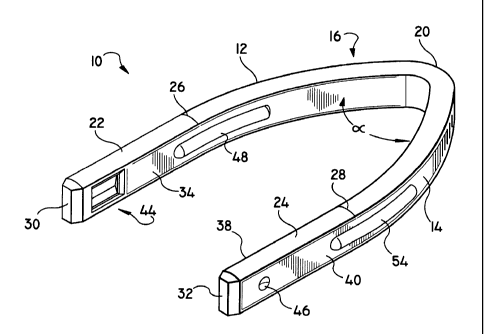
Referring to Figs. 1 and 2, the advantageous
surgical clip 10 has a bail portion 16 with first and
second gently curved back portions 12 and 14 which meet
at a single, sharply defined bend or apex 20.
Preferably, the angle "a" to be formed at apex 20 is no
more than about 100°. First and second substantially
straight legs 22 and 24 extend from regions 26 and 28
which demarcate the ends of curved back portions 12 and
14. The bail portion 16 of the clip 10 terminates at
CA 02213887 1997-08-26
_7_
regions 26 and 28 where curved back portions 12 and 14
meet straight legs 22 and 24, respectively.
First and second legs 22 and 24 are preferably parallel
to one another and terminate in free ends 30 and 32,
respectively.
The inner surfaces of the back portions 12 and 14
and associated legs 22 and 24 define tissue contacting
surfaces 34 and 38, respectively, between which tissue is
clamped during application of surgical clip 10 to tissue.
The outer surfaces of the back portions 12 and 14 and
associated legs 22 and 24 define jaw contact surfaces 36
and 40 for receiving the compression force from the jaws
of the applying apparatus. Clip 10 is dimensioned such
that the ratio of width W to total length L (i.e., the
ratio W/L) ranges from about 0.68 to about 0.64, and the
ratio of leg length A to total length L (i.e., the ratio
A/L) ranges from about 0.36 to about 0.33, wherein the
width W is the distance between the outer surfaces of the
legs, the total clip length L is the distance between the
outer edge of the apex 20 and the distal ends 30, 32 of
the legs, and the leg length A is the distance between
the juncture regions 26, 28 and the distal ends 30, 32 of
the legs. Legs 22 and 24 are preferably of equal length.
The curvature of the clip at apex 20 is the most
pronounced curvature throughout the entire clip. Thus,
apex 20 has a radius of curvature R wherein R is about
four percent (4%) of the length L of the clip 10. The
arcuate back portions 12, 14 preferably include no
radiused portion having a radius of curvature of less
than about six times the radius of curvature (R) of the
apex.
Surgical clip 10 includes an interlock protrusion 42
projecting from tissue contacting surface 38 on the
second leg 24 and an interlock recess 44 formed in tissue
CA 02213887 2005-02-08
_8_
contacting surface 34 on first leg 22 which interlock
upon closure to aid in maintaining tips 30, 32 in proper
alignment, thereby optimizing clip retention on tissue
and further minimizing the potential for twist. A dimple
46 is generally formed in jaw contacting surface 40
during formation of interlock protrusion 42.
Referring to Fig. 2A, interlock protrusion 42 can be
substantially circular whereas the recess 44 adopted to
receive protrusion 42 is preferably rectangular in shape,
and larger than protrusion 42. Recess 44 preferably
possesses beveled upper sides 44a and a synclined base
44b having an elongated line 44c oriented along the
length of leg 22 defined by the intersection of angled
planar surfaces 44e and 44f.
Surgical clip 10 is designed to exhibit improved
closure characteristics, e.g., optimal clip retention on
tissue and minimum twist during formation. Additionally,
surgical clip 10 includes structure to minimize the
amount of "gap" or distance between the tissue contacting
surfaces 34 and 38 upon closure, thereby enhancing
alignment of arms 12 and 14. Surgical clip 10 further
includes an elongated alignment rib 48 projecting from
tissue contacting surface 34 and a corresponding
alignment depression 50 formed in tissue contacting
surface 38 which is adapted to receive rib 48. An
elongate depression 52 is formed in jaw contacting
surface 36 upon formation of alignment rib 48. Similarly,
a projection or local compression rib 54 results from the
formation of alignment depression 50. Local compression
rib 54 advantageously assists in distributing the
compressive force applied by the jaws, concentrating the
force locally at the area most likely to exhibit
meaningful gap, thereby locally compressing the area to
achieve minimal gap and enhance clip retention on tissue.
CA 02213887 1997-08-26
-9-
Referring now to Figs. 5 which shows placement of
clip 10 within the apparatus jaws prior to the initiation
of closure, jaw structure 60 includes individual jaws 61
and 62 having opposing clip contacting surfaces 63 and
64, respectively. Clip 10 is shown positioned between
the jaws 61 and 62 such that the outer surfaces 36, 40 of
the parallel legs 22 and 24 are in contacting
relationship with clip contacting surfaces 63 and 64.
Referring now to Figs 6, 7, and 8, sequential views
of clip closure are illustrated. Legs 22 and 24 are
closed by the jaws such that they remain parallel to each
other and lock together, thereby minimizing the potential
for significant lateral or longitudinal misalignment. The
compression ridge 54 of the clip receives the compression
force of the jaws and, in effect, advantageously
concentrates the compressive force onto the bail area of
the clips in the vicinity of the juncture between the
bail portion and the legs (i.e., regions 26 and 28).
Referring now to Figs. 9 and 10, a row of clips 10
is shown in clip storage and feeding track 70 having base
71, sides 72, and retainer walls 73. The clips 10 are
stored in a linear array extending longitudinally through
the clip applying instrument (not shown). The distal tips
of the legs of one clip abut the bail portion of the
preceding clip. The entire row of clips is advanced,
thereby moving the most distal clip forward, ultimately
into the jaws of the instrument for application to
tissue.
Referring now to Figs 11 and 12, an alternative
embodiment is depicted wherein clip l0a includes a bail
portion 16a with first and second gently curved back
portions 12a and 14a that meet at a single, sharply
defined bend or apex 20a. First and second substantially
straight legs 22a and 24a extend from regions 26a and 28a
CA 02213887 1997-08-26
-10-
which demarcate the ends of curved back portions 12a and
14a. The bail portion 16a of the clip l0a terminates at
regions 26a and 28a where curved back portions 12a and
14a meet straight legs 22a and 24a, respectively. First
and second legs 22a and 24a are preferably parallel to
one another and terminate in free ends 30a, 32a
respectively.
The inner surfaces of the back portions 12a and 14a
and associated legs 22a and 24a define tissue contacting
surfaces 34a and 38a, respectively, between which tissue
is clamped during application of surgical clip 10a
thereto. The outer surfaces of the back portions 12a and
14a and associated legs 22a and 24a define jaw contact
surfaces 36a and 40a which receive the compression force
from the jaws of the applying apparatus. The length and
width and angle dimensions of clip l0a are preferably
similar to those of clip 10.
Surgical clip 10a includes an interlock protrusion
42a projecting from tissue contacting surface 38a and a
corresponding interlock recess 144 formed in tissue
contacting surface 34a. These features interlock upon
clip closure to aid in maintaining tips 30a, 32a in
proper alignment on tissue and to minimize twist. A
dimple 46a is formed in jaw contacting surface 40a during
formation of interlock protrusion 42a.
Like clip 10, alternate surgical clip 10a includes
an elongated alignment rib 48a projecting from tissue
contacting surface 34a and a corresponding alignment
depression 50a formed in tissue contacting surface 38a.
In contrast to clip 10, however, embodiment 10a has no
equivalent of recess 52 or of compression ridge 54.
Clips 10 and 10a can be fabricated from any
biocompatible material with properties suitable for the
CA 02213887 1997-08-26
-11-
purposes described herein. Preferred materials for clip
fabrication include stainless steel alloys and titanium,
for example.
It will be understood that various modifications may
be made to the embodiments disclosed herein. For
example, the interlocking protrusion 42 and interlock
recess 44 may be positioned on the alternate respective
legs. Therefore the above description should not be
construed as limiting, but merely as exemplifications of
preferred embodiments. Those skilled in the art will
envision other modifications within the scope and spirit
of the claims appended hereto.