Sélection de la langue

Search

Sommaire du brevet 2219699 

Énoncé de désistement de responsabilité concernant l'information provenant de tiers

Une partie des informations de ce site Web a été fournie par des sources externes. Le gouvernement du Canada n'assume aucune responsabilité concernant la précision, l'actualité ou la fiabilité des informations fournies par les sources externes. Les utilisateurs qui désirent employer cette information devraient consulter directement la source des informations. Le contenu fourni par les sources externes n'est pas assujetti aux exigences sur les langues officielles, la protection des renseignements personnels et l'accessibilité.

Disponibilité de l'Abrégé et des Revendications

L'apparition de différences dans le texte et l'image des Revendications et de l'Abrégé dépend du moment auquel le document est publié. Les textes des Revendications et de l'Abrégé sont affichés :

  • lorsque la demande peut être examinée par le public;
  • lorsque le brevet est émis (délivrance).
(12) Brevet: (11) CA 2219699
(54) Titre français: ECHANGEUR DE CHALEUR A FAIBLE CHUTE DE PRESSION
(54) Titre anglais: LOW PRESSURE DROP HEAT EXCHANGER
Statut: Réputé périmé
Données bibliographiques
(51) Classification internationale des brevets (CIB):
  • F28D 5/00 (2006.01)
  • F25B 39/00 (2006.01)
  • F25B 39/02 (2006.01)
  • F28B 1/02 (2006.01)
  • F28D 7/16 (2006.01)
(72) Inventeurs :
  • HUENNIGER, EDWARD A. (Etats-Unis d'Amérique)
(73) Titulaires :
  • CARRIER CORPORATION (Etats-Unis d'Amérique)
(71) Demandeurs :
  • CARRIER CORPORATION (Etats-Unis d'Amérique)
(74) Agent: NORTON ROSE FULBRIGHT CANADA LLP/S.E.N.C.R.L., S.R.L.
(74) Co-agent:
(45) Délivré: 2002-08-13
(22) Date de dépôt: 1997-10-30
(41) Mise à la disponibilité du public: 1998-05-21
Requête d'examen: 1997-10-30
Licence disponible: S.O.
(25) Langue des documents déposés: Anglais

Traité de coopération en matière de brevets (PCT): Non

(30) Données de priorité de la demande:
Numéro de la demande Pays / territoire Date
08/754,371 Etats-Unis d'Amérique 1996-11-21

Abrégés

Abrégé français

Cette invention concerne un échangeur de chaleur à deux parcours. Le premier parcours, en mode évaporateur, se fait dans une série de tubes immergés dans un frigorigène liquide. Ce liquide extrait la chaleur de l'eau qui circule dans lesdits tubes et se vaporise durant le processus. Le deuxième parcours se fait dans un tube unique qui n'a pas besoin d'être immergé dans le frigorigène liquide. L'objet de l'invention peut aussi servir de condenseur.


Abrégé anglais


A two pass heat exchanger is provided. The first pass includes a plurality of tubes
located in liquid refrigerant, when employed as an evaporator, whereby the liquid
refrigerant draws heat from the water flowing through the tubes causing the water to
be cooled and the liquid refrigerant to evaporate. The second pass is a single pipe
which need not be located in the liquid refrigerant. The two pass heat exchanger can
also be used as a condenser.

Revendications

Note : Les revendications sont présentées dans la langue officielle dans laquelle elles ont été soumises.


5
The embodiments of the invention in which an exclusive property or privilege
is claimed are defined as follows:
1. A heat exchanger comprising:
a shell and a pair of end pieces sealed to said shell;
a first tube sheet coacting with a first one of said pair of end pieces to
define an intermediate water box;
a second tube sheet coacting with a second one of said pair of end
pieces and a divider plate to define an inlet water box and an outlet water
box;
said first and second tube sheets coacting with said shell to define a
chamber;
a first pass including a plurality of heat transfer tubes extending from
said inlet water box through said chamber to said intermediate water box;
a second pass defined by a single, large diameter pipe extending from
said intermediate water box through said chamber to said outlet water box
whereby a
water circuit is serially defined by said inlet water box, said first pass,
said
intermediate water box, said second pass and said outlet water box; and
wherein
liquid refrigerant is located in said chamber and said first pass is in said
liquid
refrigerant, the second pass being located above said liquid refrigerant.
2. The heat exchanger of claim 1 wherein:
said shell is of a generally cylindrical shape and is horizontally
oriented;
a first port is located at the bottom of said shell and is in fluid
communication with said chamber; and
a second port is located at the top of said shell and is in fluid
communication with said chamber.


6
3. The heat exchanger of claim 2 wherein said first port is a liquid inlet
and said heat exchanger is an evaporator.
4. The heat exchanger of claim 2 wherein said first port is a liquid outlet
and said heat exchanger is a condenser.

Description

Note : Les descriptions sont présentées dans la langue officielle dans laquelle elles ont été soumises.

CA 02219699 1997-10-30


LOW PRESSURE DROP HEAT EXCHANGER

Shell and tube heat exchangers, of the kind where water flows through a plurality of
tubes in heat ll~ref relationship with a refrigerant on the shell side, are often used as
evaporators and con~n~ers, along with at least one compressor and other components
to create an assembled water chilling unit. As an assembly, the ch~nging of one
component often has an impact on the other structure. For example, the evaporator
may serve as the support for the conll)lessor or condenser.

Another general constraint in chiller design is to have an even number of passes on
the waterside so that all of the water connections can be located at one end of the heat
exchanger shell, thus pe~ g the cleaning or servicing of the tubes from the other
end without disturbing the water connections.

There are occasions where it is desired to reduce heat exchanger size to meet a given
set of thermal and pres~ul~ drop re~luirements, yet such a reduction of the exchanger
shell may not be possible due to the interrelationship of the various co~ ~nents of the
chiller. For example, to match desired pelro,lllallce characteristics, it may bedesirable to use a short length condenser shell with in combination with a long length
cooler shell, but the chiller ~sembly would be colllpl~llfised as a result.

The reduced heat exchange It~ui~lent for a heat exchanger is addressed by
providing a two pass design with essentially all of the required heat transfer taking
place in one pass. The one pass employs tubes having the desired diameters and
surface characteristics for the desired heat transfer and press~e drop while the second
or return pass employs a single large diameter tube or pipe. Specifically, the second
pass of a two pass shell and tube heat exchanger has the normal compliment of tubes
replaced with a return pipe. This allows a drastic reduction in the total number of heat
exchanger tubes, when very high heat transfer performance is not a re~luilellle~without the usual accoll,p~ying increase in water side ples~ule drop. Additionally,
this configuration allows the m~inten~nce of relatively high water side velocities in
the tubes of the first pass for the effective use of the heat t-~r~l surface. In an

CA 02219699 1997-10-30


evaporator, because the second pass would have only nominal heat transfer due to its
limited heat transfer surface area, the second pass need not be located within the liquid
refrigerant which permits the lowering of the refrigerant level and thereby the
refrigerant charge in the system.

It is an object of this invention to permit the removal of substantial members of heat
exchanger tubes without sacrificing waterside pres~ drop and pumping power.

It is another object of this invention to make cost effective use of enhanced heat
transfer tubing by keeping waterside velocities relatively high without the usual
increase in overall heat exchanger waterside pres~u,e drop.

It is a further object of this invention to allow for the optimi7~tion of heat eY(~h~ngers
for use in water chiller units without conlplol"ising the design of the other chiller
components.

It is another object of this invention to reduce the refrigerant charge in a refrigeration
system. These objects, and others as will become app~ellt hereinafter, are
accolllplished by the present invention.

Basically, a two pass heat exchanger becomes the equivalent of a one pass heat
exchanger by having the second pass be a single pipe serving primarily as a return
flow. The heat exchanger may be used as either an ~ol~lor or a condeDser.

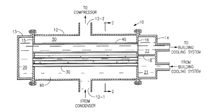
Figure 1 is a sectional view of a heat eYc~ lger employing the present invention; and

Figure 2 is a sectional view taken along line 2-2 of Figure 1.

In the Figures, the numeral 10 generally deei~tes a two pass shell and tube heatexchanger which is illustrated as a ~pol~lor, but a condenser would only differ in its
fluid connections, not in its structure. Heat exch~nger 10 has a generally cylindrical
shell 12 with end pieces 13 and 14, respectively. End piece 13 coacts with tube sheet

CA 02219699 1997-10-30


15 to define intermediate water box 20. End piece 14 coacts with tube sheet 16 and
divider plate 18 to define inlet water box 21 and outlet water box 22, respectively.
Heat exchanger 10 has a first pass heat exchanger extending from inlet water box 21
to water box 20 and includes a plurality of small diameter heat transfer tubes 30.
Typically, the tubes 30 are int~n~lly and/or externally enhanced to promote heatexchange. The second pass heat exchanger of heat exchanger 10 is a large diameter
pipe or tube 40 extending from intermediate water box 20 to outlet water box 22.
Tubes 30 and pipe 40 are located in a generally cylindrical chamber 50 defined by
shell 12 and tube sheets 15 and 16. Charnber 50 receives liquid refrigerant 60 from
the condenser (not illustrated) via inlet 12-1 when operated as an evaporator, as
illustrated. Because pipe 40 is generally not relied on for providing heat transfer, the
level of the liquid refrigerant 60 need only be above tubes 30, and need not cover pipe
40. The heat transfer area of pipe 40, as colllpaled to the total of tubes 30 will be
small. When operated as a con~en~er, 12-2 is an inlet receiving gaseous refrigerant.
The gaseous refrigerant con-lçn~s due to heat transfer to the water in tubes 30 and
conrlçn~e~ liquid refrigerant is drawn offthrough 12-1 which functions as an outlet.

In operation as an evaporator, liquid refrigerant 60 is supplied from the condenser (not
illustrated) via inlet 12-1 to cha.~r 50 where it extracts heat from and thereby cools
the water passing through tubes 30 while the liquid refrigerant 60 t~olalcs. Thegaseous refrigerant passes from cl~er 50 via outlet 12-2 to the suction of the
col~ressor (not illustrated). Water from the closed loop cooling circuit of the
refrigeration system (not illustrated) is supplied from the building cooling system to
inlet water box 21. The water then passes through tubes 30 in heat exrl~qnge
relationship with the liquid refrigerant 60. The liquid refrigerant draws heat from and
thereby cooling the water while the liquid refrigerant 60 is evaporated. The heat
transfer takes place in the first pass defined by tubes 30 with only a small amount of
heat l~sÇer being available through pipe 40, whether or not pipe 40 is located in
liquid refrigerant 60. The water passing through the second pass defined by pipe 40
enters outlet water box 22 from which it flows into the closed circuit building cooling
system to provide cooling.

CA 02219699 1997-10-30


When operated as a condenser, gaseous refrigerant is supplied to chamber 50 where it
is cooled and condensed due to heat ll~srer to the water flowing through tubes 30,
and to a lesser extend to the water flowing through pipe 40. the conden.ce~l, liquid
refrigerant collects at the bottom of chamber 50, normally below the level of tubes 30.
The liquid refrigerant is drawn off and supplied to the evaporator (not illustrated).

Dessin représentatif
Une figure unique qui représente un dessin illustrant l'invention.
États administratifs

Pour une meilleure compréhension de l'état de la demande ou brevet qui figure sur cette page, la rubrique Mise en garde , et les descriptions de Brevet , États administratifs , Taxes périodiques et Historique des paiements devraient être consultées.

États administratifs

Titre Date
Date de délivrance prévu 2002-08-13
(22) Dépôt 1997-10-30
Requête d'examen 1997-10-30
(41) Mise à la disponibilité du public 1998-05-21
(45) Délivré 2002-08-13
Réputé périmé 2009-10-30

Historique d'abandonnement

Il n'y a pas d'historique d'abandonnement

Historique des paiements

Type de taxes Anniversaire Échéance Montant payé Date payée
Requête d'examen 400,00 $ 1997-10-30
Enregistrement de documents 100,00 $ 1997-10-30
Le dépôt d'une demande de brevet 300,00 $ 1997-10-30
Taxe de maintien en état - Demande - nouvelle loi 2 1999-11-01 100,00 $ 1999-09-15
Taxe de maintien en état - Demande - nouvelle loi 3 2000-10-30 100,00 $ 2000-09-20
Taxe de maintien en état - Demande - nouvelle loi 4 2001-10-30 100,00 $ 2001-10-02
Taxe finale 300,00 $ 2002-05-28
Taxe de maintien en état - brevet - nouvelle loi 5 2002-10-30 400,00 $ 2003-08-22
Taxe de maintien en état - brevet - nouvelle loi 6 2003-10-30 350,00 $ 2004-05-13
Taxe de maintien en état - brevet - nouvelle loi 7 2004-11-01 200,00 $ 2004-09-24
Taxe de maintien en état - brevet - nouvelle loi 8 2005-10-31 400,00 $ 2005-12-14
Taxe de maintien en état - brevet - nouvelle loi 9 2006-10-30 200,00 $ 2006-09-20
Taxe de maintien en état - brevet - nouvelle loi 10 2007-10-30 250,00 $ 2007-09-21
Titulaires au dossier

Les titulaires actuels et antérieures au dossier sont affichés en ordre alphabétique.

Titulaires actuels au dossier
CARRIER CORPORATION
Titulaires antérieures au dossier
HUENNIGER, EDWARD A.
Les propriétaires antérieurs qui ne figurent pas dans la liste des « Propriétaires au dossier » apparaîtront dans d'autres documents au dossier.
Documents

Pour visionner les fichiers sélectionnés, entrer le code reCAPTCHA :


Pour visualiser une image, cliquer sur un lien dans la colonne description du document. Pour télécharger l'image (les images), cliquer l'une ou plusieurs cases à cocher dans la première colonne et ensuite cliquer sur le bouton "Télécharger sélection en format PDF (archive Zip)" ou le bouton "Télécharger sélection (en un fichier PDF fusionné)".

Liste des documents de brevet publiés et non publiés sur la BDBC .

Si vous avez des difficultés à accéder au contenu, veuillez communiquer avec le Centre de services à la clientèle au 1-866-997-1936, ou envoyer un courriel au Centre de service à la clientèle de l'OPIC.


Description du
Document 
Date
(yyyy-mm-dd) 
Nombre de pages   Taille de l'image (Ko) 
Revendications 2000-11-14 2 42
Dessins représentatifs 1998-05-27 1 11
Description 1997-10-30 4 163
Revendications 1997-10-30 2 42
Abrégé 1997-10-30 1 13
Dessins 1997-10-30 1 30
Page couverture 1998-05-27 1 41
Page couverture 2002-07-09 1 37
Revendications 2001-08-28 2 44
Poursuite-Amendment 2000-09-07 2 35
Poursuite-Amendment 2001-03-01 2 74
Cession 1997-10-30 4 148
Taxes 2001-10-02 1 25
Correspondance 2002-04-09 3 87
Correspondance 2002-05-16 1 12
Correspondance 2002-05-16 1 14
Correspondance 2002-05-28 1 42
Poursuite-Amendment 2001-08-28 4 129
Poursuite-Amendment 2000-11-14 6 182
Correspondance 2004-03-10 1 2