Sélection de la langue

Search

Sommaire du brevet 2221272 

Énoncé de désistement de responsabilité concernant l'information provenant de tiers

Une partie des informations de ce site Web a été fournie par des sources externes. Le gouvernement du Canada n'assume aucune responsabilité concernant la précision, l'actualité ou la fiabilité des informations fournies par les sources externes. Les utilisateurs qui désirent employer cette information devraient consulter directement la source des informations. Le contenu fourni par les sources externes n'est pas assujetti aux exigences sur les langues officielles, la protection des renseignements personnels et l'accessibilité.

Disponibilité de l'Abrégé et des Revendications

L'apparition de différences dans le texte et l'image des Revendications et de l'Abrégé dépend du moment auquel le document est publié. Les textes des Revendications et de l'Abrégé sont affichés :

  • lorsque la demande peut être examinée par le public;
  • lorsque le brevet est émis (délivrance).
(12) Brevet: (11) CA 2221272
(54) Titre français: FILTRE DOUBLE POUR L'AIR COMPRIME
(54) Titre anglais: A TWIN FILTER FOR COMPRESSED AIR
Statut: Réputé périmé
Données bibliographiques
(51) Classification internationale des brevets (CIB):
  • B01D 35/12 (2006.01)
  • B01D 46/46 (2006.01)
(72) Inventeurs :
  • JAUHOLA, LAURI (Finlande)
  • NIKKILA, TERO (Finlande)
(73) Titulaires :
  • JAUHOLA, LAURI (Finlande)
(71) Demandeurs :
  • JAUHOLA, LAURI (Finlande)
(74) Agent: GOWLING WLG (CANADA) LLP
(74) Co-agent:
(45) Délivré: 2006-07-25
(86) Date de dépôt PCT: 1996-05-28
(87) Mise à la disponibilité du public: 1996-12-12
Requête d'examen: 2003-05-20
Licence disponible: S.O.
(25) Langue des documents déposés: Anglais

Traité de coopération en matière de brevets (PCT): Oui
(86) Numéro de la demande PCT: PCT/FI1996/000300
(87) Numéro de publication internationale PCT: WO1996/039240
(85) Entrée nationale: 1997-11-14

(30) Données de priorité de la demande:
Numéro de la demande Pays / territoire Date
952758 Finlande 1995-06-06

Abrégés

Abrégé français

L'invention porte sur un filtre double pour l'air comprimé, dans lequel il y a deux filtres (3) placés en parallèle et un système de valves (2, 4) pour diriger l'air comprimé vers un filtre choisi (3). Ce système de valves comprend des valves d'entrée (2) pour diriger l'air comprimé depuis l'entrée (1) vers le filtre choisi (3) et un système de contre-valves (4) pour diriger l'air comprimé du filtre choisi vers la sortie d'air comprimé choisie (5.1). Le système de contre-valves comprend une chambre (8) à bille formée dans la structure du logement, avec des conduits d'entrée (14) aux extrémités et un conduit de sortie (5) au centre. Une bille (9) est prévue pour fermer le conduit d'entrée (14) sur lequel il n'y a pas de pression. La chambre à bille comprend un élément filtrant (10) d'un type connu et dans la zone centrale duquel se trouve un canal de sortie (annulaire) qui reçoit le flux de sortie allant vers le conduit de sortie (5).


Abrégé anglais


The object of the invention is a twin filter for compressed air, in which
there are two filters (3) set in parallel and an arrangement
of valves (2, 4) to direct compressed air through a selected filter (3), which
arrangement of valves includes inlet valves (2) to distribute
compressed air from the inlet (1) to the selected filter (3) and an
arrangement of counter-valves (4) to direct the compressed air from the
selected filter to the compressed air outlet (5.1). The arrangement of counter-
valves includes a ball chamber (8) formed in the housing
structure, at the ends of which are inlet connections (14) and an outlet
connection (5) in the centre. A ball (9) is arranged to close that inlet
connection (14) in which there is no pressure. The ball chamber consists of a
filter element (10) that is, as such, known, in the central area
of which a ring-like outlet channel (11) is formed, which collects the outlet
flow to the outlet connection (5).

Revendications

Note : Les revendications sont présentées dans la langue officielle dans laquelle elles ont été soumises.


6

CLAIMS

1. A twin filter for compressed air, in which there are
two filters set in parallel and an arrangement of valves
to direct compressed air through a selected filter, which
arrangement of valves includes inlet valves to distribute
compressed air from an inlet to the selected filter and
an arrangement of counter-valves to direct the compressed
air from the selected filter to a compressed air outlet,
which arrangement of counter-valves includes a housing
with two counter-valves opposing each other and connected
to one another by a chamber, via which inlets to the
chamber connections are connected with a central outlet
connection which extends to an outlet channel, and in
which a ball is arranged to close that chamber inlet in
which there is no pressure, wherein the chamber consists
of a cylindrical cage structure to carry the ball, in
which the counter-valves are formed at the ends of this
chamber, while the ball acts as a shut-off member at each
end in turn.

2. A twin filter in accordance with Claim 1, wherein
the cage structure is formed by a filter element, and
which has an annular outlet channel formed in the centre
of it, which collects the outlet flow from the outer
surface of the filter element into the outlet connection.

3. A twin filter in accordance with Claim 2, wherein
the ball chamber consists of longitudinal holes drilled
to the chamber inlets, a cylindrical space with a greater
diameter than the holes for the filter element, and a
central annular outlet channel of still greater diameter.

4. A twin filter in accordance with Claim 3, wherein at
each end of the filter element a flat ring gasket is


7

used, which extends around the opening of the
corresponding chamber inlet, so that the flat ring gasket
remains between the ball and the edge of the inlet.

5. A twin filter in accordance with any one of Claims 2
to 4, wherein the filtration limit of the filter element
is for particles 2 to 50 times greater than the twin
filters.

6. A twin filter in accordance with Claim 5, wherein
the filtration limit is in the range 5 to 200µ.

7. A twin filter in accordance with any one of Claims 2
to 6, wherein said housing is in two parts, with the
interface located at the end of the annular outlet
channel.

8. A twin filter in accordance with any one of Claims 2
to 7, wherein the inlet valves are formed by a single
three-way valve, in which there is a T-channel ball or
similar arranged in such a way that the compressed air
distribution changes smoothly from one side to the other
without closing in the intermediate position.

9. A compressed air counter-valve arrangement for
leading compressed air from a selected inlet connection
to an outlet, which counter-valve arrangement consists of
a housing with two counter-valves set opposite one
another and linked to each other by a ball chamber, to
which valves the chamber inlet is connected, with a
central outlet connection which extends to an outlet
channel, and in which a ball is arranged to close that
chamber inlet that has no pressure, wherein the ball
chamber is formed by a filter element, and in which the


8

counter-valves are formed in the ends of the ball
chamber, with the ball acting as a closing member at each
end in turn, and in which there is an annular outlet
channel formed in the central area of the chamber, which
collects the outlet flow into the outlet connection.

10. A counter-valve arrangement in accordance with
Claim 9, wherein at each end of the filter element a flat
ring gasket is used, which extends round the chamber
inlet, so that the flat ring gasket remains between the
ball and the chamber inlet.

11. A counter-valve arrangement in accordance with
either one of Claims 9 and 10, wherein said housing is in
two parts with the interface located at the end of the
annular outlet channel.


Description

Note : Les descriptions sont présentées dans la langue officielle dans laquelle elles ont été soumises.


CA 02221272 1997-11-14
WO 96/39240 PCT/FI96/00300
1
A TWIN FILTER FOR COMPRESSED AIR
The object of the invention is a twin filter for compressed air,
in which there are two filters set in parallel and a set of
valves for directing the compressed air through the selected
filter, the set of valves including inlet valves to distribute
the compressed air from the inlet to the selected filter and an
arrangement of counter valves to direct the compressed air from
the selected filter to the compressed air outlet, which arran-
gement of counter valves consists of two counter valves that are
set opposite one another and are connected to one another by a
chamber, to which valves are connected inlet connections and an
outlet connection, and in which a ball is arranged to close the
unpressurized inlet connection. The invention is also concerned
with an arrangement of counter valves for other purposes.
Modern compressed air filters use synthetic cylindrical pipes,
elements, which are set into the water-removal cup, when the
compressed air filter can also separate water, in addition to
filtering. Filter elements of this type are made by several
manufacturers, among them the American company Numatics, MI.
Such filter elements are made with different grades of coar-
seness, so that it is possible to speak of, for example, a 5~
element. This means that such an element will not permit par-
ticles with a diameter greater than 5~ to pass through it. The
element filter must be changed now and then, when the pressure
loss across it becomes too great to use. The flow through the
filter must then be cut. Twin filters are therefore used for
uninterrupted air distribution, these having two filters set in
parallel in such a way that, with the aid of a suitable arran-
gement of valves, the flow can be switched from one side to the
other. A blocked filter can then be changed at the same time as
the flow continues unbroken through the other filter.
In one known twin filter, there is a T-piece, after which there
are various shut-off valves, by means of which the flow can be
manually opened to the desired side and correspondingly shut off
from the other side. There is a danger that the operator may


CA 02221272 2005-10-12
2
close both shut-off valves. On one side of the filters two
spring-loaded counter-valves are used, in both of which a ball moves
in a pressure chamber formed by a drilled hole, both chambers being
connected to the other by a connecting drilled hole. Channels are
led from the filter to the ends of the ball chamber while the flow
exits from the middle of the connecting hole. The spring then closes
the opposite counter-valve, shutting the valve that has been cut
off. However, a counter-valve arrangement of this kind limits the
flow.
This invention is intended to create a new kind of twin filter for
compressed air, which has new characteristics compared to known twin
filters, while also making the operation of a twin filter easier,
without the risk of operating errors.
The characteristic features of a twin filter for compressed air
according to the invention are described in the accompanying Claims.
It is most advantageous, if the cage structure that carries the ball
is formed by a filter element that is as such known, but mechanical
structures are also possible in principle. A filter element can be
used to create a suitable pressure loss, which will drive the ball
reliably to the other end.
A twin filter according to the invention together with a filter
element used in the ball chamber also provides the additional
advantage that, if filter elements run out, for a short period there
is still the pressure chamber coarse filter left after the filter
proper, which is in any event preferable to a break in operation or
a total lack of any filter. Other advantages and embodiments of the
invention appear later.
In what follows, the invention is illustrated by reference to the
accompanying Figures, which show one twin filter for com-
pressed air in accordance with the invention.


CA 02221272 2005-10-12
3
Figure 1 shows the flow diagram for a twin filter for compressed air
according to the invention.
Figure 2 shows front view of a compressed air filter according to
the invention.
Figure 3 shows a side view of the twin filter in Figure 1.
Figure 4 shows a top view of the twin filter in Figure 1.
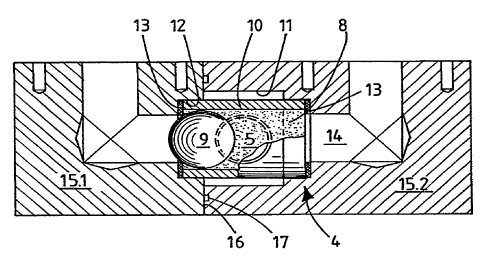
Figure 5 shows a cross-section of the ball chamber housing.
The main components of the twin filter comprise two proper
filters 3, an inlet valve 2 connecting them, and a casing component
15, in which there is a valve arrangement 4 formed by a crossover
counter-valve. The compressed air inlet 1 is a direct inlet to a
three-way valve. In this way, instead of two separate valves, a
three-way valve is used as the inlet valve 2, which has the
additional property that it does not cut off the air in the
intermediate position, but instead the change takes place smoothly.
In the intermediate position, the compressed air feed thus comes
through both filters. In valves of this kind, there may be for
example a T-channel ball.
In both filters 3, a filter element 3.1, which has typically a
coarseness grade of 5~, is used. The air enters the ball chamber
housing through the channels in casing component 15. With reference
to Figure 4, the outlet from the ball chamber housing takes place
through an outlet connection 5, located in the centre. The outlet
pressure is monitored with the aid of meter 6, which shows if the
filter becomes blocked, so that the compressed air feed must be
switched through the other element, which has been changed earlier.
Casing component 15 is advantageously formed from two parts 15.1 and
15.2, in which case the machining required is fairly simple. The
casing component has holes 14 drilled axially in both parts of the
housing. There are cylindrically machined linings for the filter
element 10 parallel to the drilled holes 14. In the larger piece
15.2, there is a concentric cylindrical machining for the outlet
channel 11. The outlet connection 5 extends to this outlet


CA 02221272 2005-10-12
4
channel 11. When the casing component 15 is assembled, the parts
15.1 and 15.2 are set opposite each other in such a way that the
filter 10 and the flat ring gaskets 13 at its ends remain in the
cylindrical space 12. In addition, the ball 9 is naturally placed
inside element 10. Ring gasket 17 is used in the interface 1.6
between parts 15.1 and 15.2. The counter-valves are formed at the
ends of the same chamber when ball 9 acts as a shut-off member at
each end in turn.
If the coarseness of the proper filters is 5~, a filter element l0
with a coarseness of, e.g. 40~. is used in this ball chamber. Filter
element Numatics type EKF30A has been tested. This means that in an
emergency there need not be any filter in the twin filter, all
filtration being taken care of by this coarser filter element 10.
Naturally, situations of this kind should be avoided, because
changing filter 10 will cause a break in flow. The coarseness of the
filter element should be 2 - 50 times greater than in the proper
filter, and should be generally in the range 5 - 200.
During operation, the flow from the pressure side pushes the ball 9
against the edges of the opening of the drilled hole 14 of the
opposite inlet connection. The flat ring gasket 13 extends, however,
to the edges of the opening in such a way that the ball is never in
direct contact with the edges of the opening.
In summary, it can be stated that a twin filter according to the
invention has the advantage of providing more reliable operation by
eliminating an operating error, in which both separate valves are
closed simultaneously. The three-way valve used never shuts the flow
into the intermediate position, so that the change of the filter
element takes place without a break in flow. The crossover counter
valve according to the invention permits a greater flow
than previously through the ball chamber, while also
providing possible additional filtering for a situation in


CA 02221272 1997-11-14
WO 96/39240 PCT/FI96/00300
which the proper filter element is blocked and a new element is
not available.
It is naturally possible to use the counter-valve arrangement
5 according to the invention elsewhere than in a twin filter. It
can be used to control two inlet sources entering the same line.

Dessin représentatif
Une figure unique qui représente un dessin illustrant l'invention.
États administratifs

Pour une meilleure compréhension de l'état de la demande ou brevet qui figure sur cette page, la rubrique Mise en garde , et les descriptions de Brevet , États administratifs , Taxes périodiques et Historique des paiements devraient être consultées.

États administratifs

Titre Date
Date de délivrance prévu 2006-07-25
(86) Date de dépôt PCT 1996-05-28
(87) Date de publication PCT 1996-12-12
(85) Entrée nationale 1997-11-14
Requête d'examen 2003-05-20
(45) Délivré 2006-07-25
Réputé périmé 2011-05-30

Historique d'abandonnement

Il n'y a pas d'historique d'abandonnement

Historique des paiements

Type de taxes Anniversaire Échéance Montant payé Date payée
Le dépôt d'une demande de brevet 150,00 $ 1997-11-14
Enregistrement de documents 100,00 $ 1997-12-16
Taxe de maintien en état - Demande - nouvelle loi 2 1998-05-28 50,00 $ 1998-05-14
Taxe de maintien en état - Demande - nouvelle loi 3 1999-05-28 50,00 $ 1999-05-14
Taxe de maintien en état - Demande - nouvelle loi 4 2000-05-29 50,00 $ 2000-05-12
Taxe de maintien en état - Demande - nouvelle loi 5 2001-05-28 75,00 $ 2001-05-07
Taxe de maintien en état - Demande - nouvelle loi 6 2002-05-28 150,00 $ 2002-05-01
Taxe de maintien en état - Demande - nouvelle loi 7 2003-05-28 150,00 $ 2003-04-29
Requête d'examen 400,00 $ 2003-05-20
Taxe de maintien en état - Demande - nouvelle loi 8 2004-05-28 200,00 $ 2004-05-05
Taxe de maintien en état - Demande - nouvelle loi 9 2005-05-30 200,00 $ 2005-04-28
Taxe de maintien en état - Demande - nouvelle loi 10 2006-05-29 250,00 $ 2006-05-04
Taxe finale 300,00 $ 2006-05-11
Taxe de maintien en état - brevet - nouvelle loi 11 2007-05-28 250,00 $ 2007-05-07
Taxe de maintien en état - brevet - nouvelle loi 12 2008-05-28 250,00 $ 2008-05-12
Taxe de maintien en état - brevet - nouvelle loi 13 2009-05-28 250,00 $ 2009-05-06
Titulaires au dossier

Les titulaires actuels et antérieures au dossier sont affichés en ordre alphabétique.

Titulaires actuels au dossier
JAUHOLA, LAURI
Titulaires antérieures au dossier
NIKKILA, TERO
Les propriétaires antérieurs qui ne figurent pas dans la liste des « Propriétaires au dossier » apparaîtront dans d'autres documents au dossier.
Documents

Pour visionner les fichiers sélectionnés, entrer le code reCAPTCHA :


Pour visualiser une image, cliquer sur un lien dans la colonne description du document. Pour télécharger l'image (les images), cliquer l'une ou plusieurs cases à cocher dans la première colonne et ensuite cliquer sur le bouton "Télécharger sélection en format PDF (archive Zip)" ou le bouton "Télécharger sélection (en un fichier PDF fusionné)".

Liste des documents de brevet publiés et non publiés sur la BDBC .

Si vous avez des difficultés à accéder au contenu, veuillez communiquer avec le Centre de services à la clientèle au 1-866-997-1936, ou envoyer un courriel au Centre de service à la clientèle de l'OPIC.


Description du
Document 
Date
(yyyy-mm-dd) 
Nombre de pages   Taille de l'image (Ko) 
Dessins représentatifs 1998-02-27 1 17
Abrégé 1997-11-14 1 66
Description 1997-11-14 5 212
Revendications 1997-11-14 3 109
Dessins 1997-11-14 3 50
Page couverture 1998-02-27 1 62
Description 2005-10-12 5 203
Revendications 2005-10-12 3 97
Dessins représentatifs 2006-06-30 1 20
Page couverture 2006-06-30 1 56
Taxes 2006-05-04 1 38
Taxes 1998-05-14 1 33
Cession 1997-11-14 6 198
PCT 1997-11-14 8 281
Correspondance 1998-02-10 1 32
Cession 1997-12-16 3 101
Cession 1998-02-12 1 23
Taxes 2003-04-29 1 30
Poursuite-Amendment 2003-05-20 1 34
Taxes 2002-05-01 1 36
Taxes 2001-05-07 1 27
Taxes 2005-04-28 1 30
Taxes 2004-05-05 1 32
Taxes 1999-05-14 1 28
Taxes 2000-05-12 1 27
Poursuite-Amendment 2005-04-12 2 74
Poursuite-Amendment 2005-10-12 8 310
Correspondance 2006-05-11 1 39
Taxes 2007-05-07 1 30
Taxes 2008-05-12 1 29
Taxes 2009-05-06 1 31