Note : Les descriptions sont présentées dans la langue officielle dans laquelle elles ont été soumises.
CA 02225969 1997-12-24
ZOOM LENS SYSTEM
BACKGROUND OF THE INVENTION
(a) Field of the Invention
The present invention relates to a zoom lens system, more particularly
to a zoom lens system for a single lens reflex camera capable of compensating
a
change of an introversive coma at a telephoto position.
(b) Description of the Related Art
A conventional zoom lens system for a single lens reflex camera
to includes a first lens group of a positive refractive power which is movable
toward an object along an optical axis for a magnification change, a second
lens
group of a negative refractive power which is fixed, a third lens group of a
positive refractive power compensating an image plane when changing a
magnification, and a fourth lens group of a negative refractive power which is
movable toward an object as the first lens group moves for a magnification
change.
However, the conventional zoom lens system with four lens groups has
a problem of an introversive coma at a telephoto position, where an off-axis
aberration varies greatly because an exit angle of an incident light beam
2o entering the lens at an arbitrary angle changes as the fourth lens group
moves.
-1-
A~~ZOOMLEN2-CLN.aoc
CA 02225969 1997-12-24
SUMMARY OF THE INVENTION
In view of the shortcomings of the prior art described above, it is an
object of the present invention to provide a zoom Iens system capable of
compensating an introversive coma at a telephoto position where an off-axis
aberration is compensated.
To achieve this object and in accordance with the purpose of the
invention, the zoom lens system comprises;
a first lens group of a positive refractive power that moves linearly
toward an object when changing a magnification;
1o a second lens group of a negative refractive power which is fixed
against the image plane;
a third lens group of a positive refractive power that moves non-
linearly toward the object when changing a magnification; and
a fourth lens group of a negative refractive power that moves linearly
i5 toward the object when changing a magnification.
The zoom lens system according to the present invention also satisfies
following conditions:
0.3xfW<f3,4<0.5xfw
0.2x fl <_ ~f2~ 5 0.4 x fl
20 where fW is a focal length of the zoom lens system at a wide angle
position,
f3, .~ is an effective focal length of the third lens group and the fourth
-2-
A1ZOOMLEN2-CLN.COc
CA 02225969 2000-09-29
lens group,
f2 is a focal length of the second lens group, and
f~ is a focal length of the first lens group.
In one embodiment, the first lens group includes a convex lens and
a concave lens cemented thereto.
In a further embodiment, the second lens group includes at least a
concave lens and a meniscus lens cemented thereto.
BRIEF DESCRIPTION OF THE DRAWINGS
The above object and features of the present invention will be
apparent from the following description of the preferred embodiment
with reference to the accompanying drawings.
FIG. 1 A is a sectional view illustrating a lens group of a zoom lens
system at a wide angle position in accordance with a preferred
embodiment of the present invention;
FIG. 1 B is a sectional view illustrating a lens group of a zoom lens
system at a normal position in accordance with a preferred embodiment
of the present invention;
FIG. 1 C is a sectional view illustrating a lens group of a zoom lens
system at a telephoto position in accordance with a preferred embodiment
of the present invention;
3
CA 02225969 2000-09-29
FIG. 2A is a view illustrating aberrations of the zoom lens system
at a wide angle position in accordance with a preferred embodiment of
the present invention;
FIG. 2B is a view illustrating aberrations of the zoom lens system
at a normal position in accordance with the first preferred embodiment of
the present invention;
3a
CA 02225969 1997-12-24
FIG. 2C is a view illustrating aberrations of the zoom lens system at a
telephoto position in accordance with the first preferred embodiment of the
present invention;
FIG. 3A is a view illustrating aberrations of the zoom lens system at a
wide angle position in accordance with a second preferred embodiment of the
present invention;
FIG. 3B is a view illustrating aberrations of the zoom lens system at a
normal position in accordance with the second preferred embodiment of the
present invention; and
1o FIG. 3C is a view illustrating aberrations of the zoom lens system at a
telephoto position in accordance with the second preferred embodiment of the
present invention.
DETAILED DESCRIPTION OF THE PREFERRED EMBODIMENTS
Reference will now be made to the preferred embodiments of the
i5 present invention, examples of which are illustrated in the accompanying
drawings.
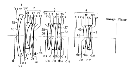
Referring to Figs. lA~lC, a zoom lens system in accordance with the
preferred embodiment of the present invention includes counting from the
object side,
2o a first lens group 1 of a positive refractive power having two lenses
which is linearly movable toward an object for a magnification change,
a second lens group 2 of a negative refractive power having three lenses
_.
A.1ZOOMLEN2-CLN doc
CA 02225969 2000-09-29
which is fixed against the image plane,
a third lens group 3 of a positive refractive power having four
lenses which is non-linearly movable toward the object for a
magnification change, and
a fourth lens group 4 of a negative refractive power have three
lenses which is linearly moveable toward an object for magnification
change.
The first lens group 1 has one concave lens 15 which is concave
toward an image plane, and one convex lens 16 cemented thereto. The
second lens group 2 has a first lens 21 of a negative refractive power
which is concave toward an image plane, a second lens 22 of a positive
refractive power which is concave toward an image plane and is
cemented to the first lens 21, and a third lens 23 of a negative refractive
power which is concave toward an object. So, because the second lens
group 2 has a negative refractive power, the light received is diverged.
Therefore, the second lens group 2 compensates an introversive coma.
In a preferred embodiment, the first lens 21 is a concave lens,
concave toward an image plane, and, the second lens 22 cemented to the
first lens 21 is a miniscus lens of a positive refractive power which is
concave toward an image plane.
5
CA 02225969 2000-09-29
The third lens group 3 has two double convex lenses 35, 36 and
one meniscus lens 37 which is concave toward an object, and one convex
lens 38.
The fourth lens group 4 has a double convex lens 45 and two
meniscus lenses 46, 47, one of which is cemented to the double convex
lens.
To change the magnification, the first lens group 1 moves linearly
toward an object and a second lens group 2 is fixed against an image
plane. The third lens group 3 moves non-linearly toward the object as the
first lens group 1
Sa
CA 02225969 1997-12-24
moves, and the fourth lens group 4 moves linearly toward the object according
to the third lens group 3.
The first lens group 1 is composed of two lenses, converges the light
entering from the object side. The light refracted by the first lens group 1
enters
the second lens group 2 having three lenses, and finally diverges. The first
lens
21 of a negative refractive power and the second lens 22 of a positive
refractive
power of the second lens group 2 correct an introversive coma caused by the
axis aberration to improve the quality of the image.
The third lens group 3 has four lenses, and converges the light received
l0 from the second lens group 2 . The fourth lens group 4 has three lenses,
and
diverges the light received from the third lens group 3. In addition, the zoom
lens system in accordance with the first and second preferred embodiments of
the present invention satisfies the following conditions:
0.3 x fw < f3.4< 0.5 x fW _________________________ ~1~
0.2 x fl <_ (f2~ <_ 0.4 x f 1 _________________________ ~2~
where fW is a focal length of the zoom lens system at a wide angle position,
fa, ~
is an effective focal length of the third lens group and the fourth lens
group, f2 is
a focal length of the second lens group, and fl is a focal length of the first
lens
group.
2o Condition 1 focuses on the minimization of the total length of the zoom
lens system. That is, condition 1 defines an optimum range of the focal length
of the third lens group 3.
-6-
A.~ZOOMLEN2-CLN doc
CA 02225969 1997-12-24
When the effective focal length f3,.~ of the third lens group 3 and the
fourth lens group 4 exceeds the upper limit in condition 1, the focal length
f3 of
the third lens group 3 becomes long. The longer focal length results in a
longer
distance between two conjugate points of the third lens group 3, which causes
the total length of the zoom lens system to be long. On the other hand, when
the effective focal length fs,~ of the third lens group 3 and the fourth lens
group
4 is below the lower limits in condition 1, a focal length f3 of the third
lens
group 3 becomes too short. A too-short focal length fs of the third lens group
3
makes it difficult to compensate all the aberrations such as spherical
aberration.
When the absolute value ~fz~ of the focal length f2 of the second lens
group 2 is below the lower limit in condition 2, it is difficult to decrease
the
influence of the divergent power of the second lens group 2 while keeping the
zoom lens size compact. On the other hand, when the absolute value ~f2~
exceeds the upper limit in condition 2, lenses with large aperture sizes are
i5 needed to compensate the decreased amount of oblique ray.
The data according to the first preferred embodiment of the present
invention is shown in Table 1. In accordance with the first preferred
embodiment, the F number ranges from 4 to 5.8, and the focal length ranges
from 71.5mm to 201.7mm. In the tables, r represents a radius of curvature, d
2o represents a distance between lenses or thickness of a lens, nd represents
a
refractive power for d-line, and v represents an Abbe number of a lens. In
each
of these Tables, all units of length are denominated in millimeters.
A 1ZOOMLEN2-CLN.doe
CA 02225969 1997-12-24
Table 1
Surface Radius of Distance(di)Refractive Abbe
No. Curvature(ri) Power(nd) Number (v)
1 82.78000 1.5000 1.80518 25.46
2 43.93800 5.2800 1.65844 50.85
3 -337.05300 A
4 1422.87600 1.0000 1.63854 55.45
19.63200 3.7200 1.80518 25.46
6 47.09200 2.5800
7 -47.36700 1.0000 1.77250 49.62
8 113.79500 B
9 87.85700 3.2700 1.48749 70.44
-60.00000 0.1500
11 47.37000 4.4800 1.51680 64.20
12 -47.54400 1.0000 1.80518 25.46
13 833.76900 0.1500
14 38.80300 2.7800 1.48749 70.44
336.35900 1.5000
16 0.00000 C
17 0.00000 12.4500
18 71.42000 3.6900 1.64769 33.84
19 -33.15400 1.1000 1.63854 55.45
-126.31300 2.2900
21 -24.18600 1.1000 1.77250 49.62
~L -141.40300
A, B, and C represent variable distances between surfaces in
accordance with the wide angle position, the normal position, and the
telephoto
position , as shown in Table 2. Bf represents a back focal length.
Table 2
Focal Wide Angle Normal Telephoto
Len h Position f=71.5Position f=109.0Position f=201.
A 1.251 20.396 39.663
B 20.673 13.758 1.282
C 18.998 18.234 19.005
- Bt I 37.496 45.175 56.880
_g_
A:1100MLEN2-CLN.doc
CA 02225969 1997-12-24
f l 31.15 -__~. 31.37 _31.15
The focal length fl of the first lens group 1 according to the first
preferred embodiment of the present invention is 120.31mm, the focal length f2
of the second lens group 2 according to the first preferred embodiment of the
present invention is -32.19mm.
The data according to the second preferred embodiment of the present
invention is shown in Table 3. In accordance with the second preferred
embodiment of the present invention, the F number ranges from 4 to 5.8, and
the focal length ranges from 71.3mm to 201.8mm.
to Table 3
Surface Radius of Distance(di)Refractive Abbe
No. Curvature(ri) Power(nd) Number (v)
1 81.87800 1.6000 1.80518 25.46
2 43.44200 5.6300 1.65844 50.85
3 -336.23900 A
4 -321.81100 1.2000 1.63854 55.45
5 19.95200 3.4300 1.80518 25.46
6 53.67000 2.1100
7 -52.98800 1.0000 1.77250 49.62
8 97.11000 B
9 71.99500 3.2600 1.51155 67.67
-71.99500 0.1500
11 47.30900 4.5000 1.51680 64.20
12 -47.30900 1.1000 1.83606 24.25
13 6110.30800 0.1500
14 44.90200 2.6000 1.51680 64.20
509.90600 1.4300
16 0.00000 C
17 0.00000 12.4500
18 66.81200 3.4300 1.64769 33.84
19 -37.44700 1.1000 1.63854 55.45
I
-9-
A.1ZOOMLEN2-CLN doc
CA 02225969 1997-12-24
20 -160.95500 2.5000
21 -24.35300 1.1000 1.77250 49.62
22 -134.81100
A, B, and C represent variable distances between surfaces in
accordance with the wide angle position, the normal position, and the
telephoto
position , as shown in Table 4. Bf represents a back focal length.
Table 4
Focal Wide Angle Normal Telephoto
Len th Position f=71.3Position f=108.8Position f=201.8
A 1.593 20.657 39.794
B 20.673 13.760 1.282
C 18.998 18.234 19.006
Bf 37.505 45.182 56.888
f3,4 31.06 31.28 31.06
The focal length fl of the first lens group 1 according to the second
preferred embodiment of the present invention is 119.28mm, the focal length f2
of the second lens group 2 according to the second preferred embodiment of the
1o present invention is -32.19mm.
As described above, the effect of the zoom lens system in accordance
with the preferred embodiment of the present invention lies in that it is able
to
obtain good image quality because coma is corrected at the telephoto position.
Moreover, the ratio of the intensity of the surrounding radiation becomes
high.
While it has been shown and described the preferred embodiments of
the invention, it will be obvious to those skilled in the art that various
changes
and modifications can be readily made therein without departing from the
-10-
A.1ZOOMLEN2-CLN.doc
CA 02225969 1997-12-24
scope and spirit of the invention as defined by the appended claims.
-11-
A.~ZOOMLEN2-CLN dx