Note : Les descriptions sont présentées dans la langue officielle dans laquelle elles ont été soumises.
CA 02228030 2005-05-16
1
1 . APPARATUS FOR MIXING A FLUID AND A LIQUID
2
3 The invention relates to apparatus for introducing a fluid
4 into a first liquid and especially a container which
introduces the fluid into the first liquid on opening of
6 the container.
7
8 In a wide number of applications, such as pharmaceuticals
9 for both human and animal use, agrochemicals and other
more general applications it may be necessary to release
11 and mix a liquid catalyst or reagent into a liquid before
12 the liquid may be used. Conventional methods involve a
13 user measuring out the liquid catalyst or reagent and then
14 adding it to the main liquid. This may cause problems in
that it is prone to human error in the measuring of the
16 amount of liquid catalyst or reagent and may also be
17 hazardous if the catalyst or reagent is toxic.
18
19 In accordance with the present invention, apparatus for
introducing a fluid into a first liquid comprises a first
21 container for containing the first liquid, the first
22 container having an opening closed by a releasable
23 closure, and a second container located in the first
24 container adjacent the opening of the first container; the
second container comprising an outer housing located in
26 the opening and an inner Container containing a fluid, the
27 inner container including a rupturable member and being
28 movably mounted in the housing for movement between a
29 closed position in which the inner container is sealed by
the housing when the releasable closure closes the
31 opening, and an open position in which the fluid within
32 the inner container is released from the inner container
CA 02228030 2005-05-16
2
1 into the first container and into contact with the first
2 liquid on release of the releasable closure, the housing
3 also including a rupturing member to rupture the
4 rupturable member on the inner container.
6. An advantage of the invention is that by using a second
7 container located adjacent the opening of the first
8 container and adapted to release a fluid into the first
9 container and into contact with the first liquid on
release of the closure, it is possible to introduce the
11 fluid into the first liquid without requiring direct
12 handling of the fluid by a user.
13
14 Preferably, the second container may include a conduit
into which the fluid passes on release of the closure and
16 the conduit extends below the surface of the first liquid
17 in the first container. Typically, the conduit extends to
18 at least adjacent the mid-section of the first liquid in
19 the first container and preferably, extends to adjacent
the bottom of the first container.
21
22 Typically, the fluid may be a gas and/or a second liquid.
23 The fluid may be pressurised to aid expulsion of the fluid
24 from the second container on release of the closure.
Typically, where the second container comprises an outer
26 housing and an inner container, pressurised gas is located
27 in the inner container with the second liquid.
CA 02228030 1998-O1-27
WO 97/05039 PCT/GB96/01803
3
1 Preferably, the inner container includes a rupturable
2 member and the housing includes a rupturing member to
3 rupture the rupturable member on the inner container.
4 Typically, the rupturable member may be a membrane.
6 Preferably, the inner container is located in an
7 initial position prior to insertion into the container
8 and on closing of the first container by the closure
9 moves the inner container to the closed position.
Typically, the second container also includes a sealing
11 device and when the inner container is in the closed
12 position the rupturing member has ruptured the
13 rupturable member of the inner container but the
14 contents of the inner container are prevented from
being released from the inner container by the sealing
16 member. Typically, the sealing member is attached to
17 the inner container and seals against the rupturing
18 member on the housing. When the inner container moves
19 to the open position the seal member no longer prevents
release of the fluid from the inner container.
21
22 Preferably, the first and second liquids may be any
23 combination of liquids. Examples of first and second
24 liquids are pharmaceutical liquids, agrochemical
liquids and any other combination of liquids which
26 requires a second liquid to be added to a first liquid
27 prior to use of the liquid mixture.
28
29 An example of a container for introducing a fluid into
a first liquid in accordance with the invention will
31 now be described with reference to the accompanying
32 drawings, in which:-
i
33
34 Fig. 1 is a cross-sectional view of a first
example of a second container in a shipping or
36 storage position;
CA 02228030 1998-O1-27
WO 97/05039 PCT/GB96/01803
4
1 Fig. 2 is a cross-sectional view of the second
2 container of Fig. 1 showing the position of the
3 second container when located in a first container
4 and the first container opening is closed;
Fig. 3 is a cross-sectional view of the second
6 container of Fig. 1 showing the position of the
7 second container when the closure on the first
8 container is released;
9 Fig. 4 is a cross-sectional view of a second
example of a second container when located in a
11 first container and the first container opening is
12 closed; and
13 Fig. 5 is a cross-sectional view through an outer
14 housing for a third example of a second container.
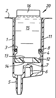
16 Fig. 1 shows a second container 20 which comprises an
17 outer housing 1 which has an upper lip 2. Extending
18 from the bottom of the housing 1 is a dip tube
19 connector 5. The housing 1 has a rupturing member 6
which extends upwards and terminates in a spike 7. A
21 dip tube (not shown) may be attached to the connector
22 5, if desired.
23
24 In the side wall of the housing 1 is a ridge 3 which
extends circumferentially around the inside of the
26 housing 1.
27
28 An inner container 11 has a lower open end which is
29 sealed by a sealing gasket 12 and a rupturable membrane
13. The gasket 12 is annular and defines a central
31 aperture 14. The container 11 also has an O-ring seal
32 8 encircling it in a circumferential recess 4 in the
33 container 11.
34
In use, the inner container 11 is filled with a liquid
36 15 and a pressurised gas 16 by means of conventional
CA 02228030 1998-O1-27
WO 97105039 PCT/GB96/01803
1 technology used to fill pressurised dispenser packs,
2 commonly known as aerosol containers. The inner
3 container 1l is then inserted into the outer housing 1
4 and pushed into the outer housing 1 until the O-ring 8
5 engages with the ridge 3. This position is
h
s
own in
6 Fig. 1. In this position the membrane 13 is above the
7 member 6 and spike 7.
8
9 The outer housing 1 and the inner container 11 are then
inserted into the opening of a container, the outer
11 housing 1 fits inside the opening and the dip tube (if
12 fitted) extends into a first liquid in the container.
13 The outer housing 1 is supported in the opening by the
14 upper lip 2 which rests on the top of the opening. A
closure such as a threaded cap is then applied to the
16 container to close the container. On application of
17 the closure to the first container, the inner container
18 11 is moved downwards and moves to the position shown
19 in Fig. 2. An adhesive section may be provided on the
top end of the container 11 and serves to attach the
21 top end of the container 11 to the inside of the
22 closure when the closure is applied to the container.
23
24 When the closure is applied to the first container, the
inner container 11 moves to the position shown in Fig.
26 2. When this happens, the spike 7 bursts the
27 rupturable membrane 13 and the member 6 extends into
28 the aperture 14 in the gasket 12. In this position the
29 liquid 15 and gas 16 are prevented from escaping from
the inner container 11 by the gasket 12 and member 6
31 which seal against each other to prevent release of the
32 liquid 15 and gas 16 from the container 11.
z
33
34 The inner container 11 remains in the position shown in
Fig. 2 until a user releases the closure from the first
36 container. When this occurs, the inner container 11
CA 02228030 2005-05-16
6
1 moves to the position shown in Fig. 3. In this position the
2 gasket 12 becomes unsealed from the member 6 and liquid 15
3 is forced out of the container 11 by the pressurised gas 16
4 in the direction of arrows 17 and into the dip tube
connector 5. The liquid 15 then passes through the dip tube
6 connector 5 and into the first liquid in the first
7 container, via the dip tube if fitted. On removal of the
8 closure, the housing 1, inner container 11 and dip tube o f
9 fitted) are removed from the first container because the
inner container 11 is attached to the closure by adhesive.
11 The liquid 15 enters the first liquid through the dip tube
12 connector 5 and dip tube (if fitted) before the housing 1,
13 inner container 11 and dip tube (if fitted) are removed from
14 the first container. Liquid is prevented from passing up
between the housing 1 and the inner containers 11 by the 0-
16 ring 8.
17
18 It is possible that upward movement of the container 11 from
19 the position shown in Fig. 2 to the position shown in Fig. 3
could be aided by a spring located between the gasket 12 and
21 the bottom of the outer housing 1.
22
23 Hence, the container 11 may move to the position shown in
24 Fig. 3 by use of a spring and/or by means of the pressure
within the container 11 which reacts against the member 6 to
26 push the inner container 10 to the position shown in Fig. 3.
2?
28 A second example of a second container 30 is shown in Fig.
29 4. In the container 30, an inner container 41 is similar to
the container 11 shown in Figs. 1 to 3 and also has an 0-
31 ring 8. The main difference is that recess 42 is extended
32 compared to the recess 4 in inner container 11.
CA 02228030 1998-O1-27
WO 97/05U39 PCT/GB96/01803
7
1 However, outer housing 31 is different to the outer
2 housing 1. The housing 31 comprises an upper lip 32
3 which is connected to a lower portion 33 by arm
4 portions 34. The lower ends of arm portions 34 form
protruding nibs 35 which engage in the recess 42. Over
6 the end of the lower portion 33 is a dip tube adaptor
7 36 which has a connector 37 to which a dip tube may be
8 fitted, if desired. The adaptor 36 may be secured to
9 the lower portion 33 by glue or by a snap connection.
11 In use, the second container 30 operates and is used in
12 a similar manner to the second container 20. The
13 adaptor 36 directs the liquid 15 as it flows out of the
14 inner container 41 into the liquid in the first
container, via the dip tube if fitted.
16
17 An example of a modified outer housing 50 is shown in
18 Fig. 5. The outer housing 50 is similar to the outer
19 housings 1, 31. The main differences are that there is
a central portion 51 which has a recessed hollow
21 section 52 which communicates with side ports 53. On
22 the edge of the portion 51 is a spike 54.
23
24 In use, the outer housing 50 operates in a similar
manner to the outer housings 1, 31 except that when an
26 inner container, such as the inner container 41 or the
27 inner container 11, is pushed onto the central portion
28 51, the sealing gasket 12 of the inner container seals
29 against the outside of the ports 53 and subsequent to
this, the spike 54 punctures the membrane 13. Hence,
31 when the inner container is in a position similar to
32 the position shown in Figs. 2 and 4, the membrane 13 is
33 ruptured but ports 53 are sealed by gasket 12 to
34 prevent fluid from inside the inner container escaping
from the inner container. When the cap on the first
36 container is removed, the inner container will move to
CA 02228030 1998-O1-27
WO 97/05039 PCT/GB96/01803
8
1 a similar position to that shown in Fig. 3. This will
2 result in the gasket 12 uncovering ports 53 and fluid
3 from inside the inner container will flow out of the
4 inner container through ports 53 which direct the fluid
into the main body of the first container.
6 '
7 The outer housing 50 has the advantage that it directs
8 fluid from the inner container into the main body of
9 the first container and onto the surface of liquid
contents in the first container.
11
12 In the examples described above, the inner containers
13 may be secured to the cap of the first container, for
14 example, by putting blown polyethylene foam on the
upper end of the inner containers and welding the blown
16 polyethylene foam to blown polyethylene foam on the
17 inside top of the cap of the first container by
18 ultrasonic welding. Other possibilities include
19 friction fitting the inner container to a hollow cap
which is then secured to the inside of the cap of the
21 first container.
22
23 Modifications and improvements may be incorporated
24 without departing from the scope of the invention.
E