Sélection de la langue

Search

Sommaire du brevet 2232221 

Énoncé de désistement de responsabilité concernant l'information provenant de tiers

Une partie des informations de ce site Web a été fournie par des sources externes. Le gouvernement du Canada n'assume aucune responsabilité concernant la précision, l'actualité ou la fiabilité des informations fournies par les sources externes. Les utilisateurs qui désirent employer cette information devraient consulter directement la source des informations. Le contenu fourni par les sources externes n'est pas assujetti aux exigences sur les langues officielles, la protection des renseignements personnels et l'accessibilité.

Disponibilité de l'Abrégé et des Revendications

L'apparition de différences dans le texte et l'image des Revendications et de l'Abrégé dépend du moment auquel le document est publié. Les textes des Revendications et de l'Abrégé sont affichés :

  • lorsque la demande peut être examinée par le public;
  • lorsque le brevet est émis (délivrance).
(12) Brevet: (11) CA 2232221
(54) Titre français: EQUIPEMENT SERIE AVEC TRANSFERT DE BLOCAGE DE LIGNE C.C.
(54) Titre anglais: SERIES EQUIPMENT WITH DC LINE HOLD TRANSFER
Statut: Réputé périmé
Données bibliographiques
(51) Classification internationale des brevets (CIB):
  • H04M 3/42 (2006.01)
  • H04M 19/00 (2006.01)
(72) Inventeurs :
  • PURITS, VALENTIN (Etats-Unis d'Amérique)
(73) Titulaires :
  • MITEL NETWORKS CORPORATION (Etats-Unis d'Amérique)
(71) Demandeurs :
  • MITEL INC. (Etats-Unis d'Amérique)
(74) Agent: AVENTUM IP LAW LLP
(74) Co-agent:
(45) Délivré: 2000-09-05
(22) Date de dépôt: 1998-03-16
(41) Mise à la disponibilité du public: 1998-10-14
Requête d'examen: 1998-03-16
Licence disponible: S.O.
(25) Langue des documents déposés: Anglais

Traité de coopération en matière de brevets (PCT): Non

(30) Données de priorité de la demande:
Numéro de la demande Pays / territoire Date
08/843,250 Etats-Unis d'Amérique 1997-04-14

Abrégés

Abrégé français

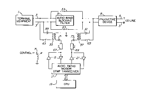
Circuit de ligne série d'équipement téléphonique assurant la connexion entre une ligne de central (CO) et une ligne d'équipement terminal (TE). Ce circuit comporte un filtre connecté entre les lignes afin d'empêcher les signaux de messages de passer entre ces lignes et afin de faire passer du courant continu (c.c.), un circuit de dérivation c.c. comprenant un premier interrupteur série connecté entre les lignes autour du filtre, de l'équipement série connecté par l'intermédiaire d'un circuit bloquant le courant continu, et un second interrupteur série connecté aux lignes, le premier interrupteur étant ouvert lorsque le second interrupteur est fermé et inversement.


Abrégé anglais


A telephone series equipment line circuit for
connection between a central office (CO) line and a
terminal equipment (TE) line comprising a filter
connected between the lines for blocking message signals
from passing therebetween and for passing direct current
(DC), a DC bypass circuit including a first series
switch apparatus connected between the lines around the
filter, series equipment connected via a DC blocking
circuit and second series switching apparatus to the
lines, the first switch apparatus being open and closed
reciprocally to the second switch apparatus.

Revendications

Note : Les revendications sont présentées dans la langue officielle dans laquelle elles ont été soumises.


I Claim:

1. A telephone series equipment line circuit
for connection between a central office (CO) line and a
terminal equipment (TE) line comprising a filter
connected between said lines for blocking message
signals from passing therebetween and for passing direct
current (DC), a DC bypass circuit including a first
series switch means connected between said lines around
the filter, series equipment connected via a DC blocking
circuit and second series switching means to said lines,
said first switch means being open and closed
reciprocally to the second switch means.

2. A line circuit as defined in claim 1 wherein
the series equipment is devoid of a CO line hold
circuit.

3. A line circuit as defined in claim 2 in
which the series equipment is comprised of DC isolating
means for blocking DC from passing from either of the
lines into the series equipment.

4. A line circuit as defined in claim 3 in
which said switching means is comprised of relay
contacts.

5. A line circuit as defined in claim 3 in
which the filter is an audio band blocking filter.

6. A line circuit as defined in claim 1 in
which each of said lines is comprised of tip and ring
lead pairs, the first switch means is comprised of a
pair of first relay contacts respectively connected
between said tip leads and between said ring leads; the


series equipment is comprised of a pair of transformers,
a primary winding of each of the transformers being
connected via a corresponding capacitor to a
corresponding one of the tip and ring leads and via a
second relay contact to another one of the tip and ring
leads, and secondary windings of the transformers being
connected via bidirectional audio frequency paths and
impedance matching means to signal processing apparatus,
the series equipment being devoid of a CO line hold
circuit.

7. A line circuit as defined in claim 6 in
which the first and second relay contacts are
operationally associated with a single relay.

8. A line circuit as defined in claim 6 in
which the signal processing apparatus is comprised of at
least one of a modem and dual tone multifrequency (DTMF)
transceiver.

Description

Note : Les descriptions sont présentées dans la langue officielle dans laquelle elles ont été soumises.


CA 02232221 1998-03-16
llP245CA


FIELD OF THE INVENTION
This invention relates to the field of
telephony, and in particular to a circuit for
interfacing a central office line and terminal equipment
with series equipment.
BACKGROUND TO THE INVENTION
Series equipment is sometimes connected between
a central office (CO) line and terminal equipment such
as PABXs to provide specialized services, such as call
redirection, data modification, automatic recall, etc.
Typically the terminal equipment is connected either in
series with the CO line, or is connected in series with
the series equipment to the CO line. In the first case,
the series equipment must have a hold circuit to hold
the CO line "off-hook" while the series equipment is in
series with the terminal equipment line and the CO line.
In the second case the series equipment must include a
battery feed to supply a hold circuit in the terminal
equipment while the series equipment is in series with
the terminal equipment line and the CO line.
The hold circuit typically consumes up to three
watts of power, and is required to meet stringent
overvoltage safety requirements. The battery feed
supplies the internal terminal equipment hold circuit
2s with direct current, and dissipates power and has strict
noise requirements. These circuits have been found to
dissipate the majority of the power used by the series
equipment.
The dissipation of power, the meeting of
overvoltage requirements and the meeting of noise
requirements are all undesirably expensive.
Figure l is a schematic diagram of series
equipment in accordance with the prior art. Terminal
equipment l is connected via tip and ring leads of a
terminal equipment line 3 to tip and ring leads 5 of a

CA 02232221 1998-03-16


central office (CO) line, through double pole double
throw contacts 7 of a relay. Typically a protective
device 9 such as a varactor is connected across the CO
line.
s When the contacts 7 are in one position, the
terminal equipment is connected directly (cut through)
to the Co line, and therefore the direct current
supplied via the CO line is applied to the terminal
equipment, to supply the internal terminal equipment
hold circuit, for example. When the contacts 7 are in
another position, the cut through connection is severed,
and the terminal equipment is connected to the series
equipment 11.
The connection of the terminal equipment through
contacts 7 in the latter position is via DC blocking
capacitor 13 and bidirectional amplifiers 15 to signal
processing circuits 17, such as audio paths, a modem, a
dual tone multifrequency (DTMF) transceiver, etc., which
can be controlled by a microprocessor 19. The signal
processing circuits 17 are also connected via
bidirectional amplifiers 21, impedance matching circuit
23 and capacitor 25 to one winding of transformer 27.
The other winding of the transformer is
connected via DC blocking capacitor 29 to the tip and
ring leads of the CO line 5.
Due to there being DC blocking elements in
series with the CO line 5 and the terminal equipment
line 3, the internal hold circuit in the terminal
equipment cannot be used to hold the CO line. Therefore
a separate hold circuit 31 is connected across the CO
line 5. Another contact 33 is connected in series with
the hold circuit and the connection of the transformer
27, and the Co line.
Also due to the aforenoted DC blocking elements,
current from the CO line cannot be used to feed the

CA 02232221 1998-03-16


terminal equipment line 3. For that reason a battery
supply circuit 35 is connected across the terminal
equipment line, via contacts 7.
In operation, with the contacts 7 in one (upper)
switched position, and with contacts 33 open, the
terminal equipment line 3 is cut through to the CO line
5. DC is supplied from the CO line to the terminal
equipment, and the internal hold circuit in the terminal
equipment can hold the CO line offhook.
With the contacts 7 in the other (lower)
switched position, and with contact 33 closed, a DC path
from the CO line 5 to the terminal equipment line 3 is
blocked, but there is an AC path between the lines via
the series equipment 11. Due to the blocked DC path, DC
current is supplied from battery supply circuit 35, and
separate hold circuit 31 is connected to the CO line 5.
SUMMARY OF THE INVENTION
The present invention provides a series
equipment circuit between the CO line and terminal
equipment line which allows DC current to be provided
from the Co line to the terminal equipment line. It
also allows the terminal equipment hold circuit to hold
the CO line offhook. Neither a special DC supply
circuit nor a separate hold circuit is required in the
2s series equipment, as is required in the prior art
circuit. This reduces both equipment cost and wastage
of power caused by dissipation.
In accordance with an embodiment of the
invention, a telephone series equipment line circuit for
connection between a central office (CO) line and a
terminal equipment (TE) line is comprised of a filter
connected between the lines for blocking message signals
from passing therebetween and for passing direct current
(DC), a DC bypass circuit including a first series
switch apparatus connected between the lines around the

CA 02232221 1998-03-16


filter, series equipment connected via a DC blocking
circuit and second series switch apparatus to the lines,
the first switch apparatus being open and closed
reciprocally to the second switch apparatus.
s The series equipment can thus be devoid of a CO
line hold circuit, and devoid of a separate battery feed
circuit for the terminal equipment.
BRIEF INTRODUCTION TO THE DRAWINGS
A better understanding of the invention will be
obtained by considering the detailed description below,
with reference to the following drawings, in which:
Figure 1 is a schematic diagram of a series
equipment line circuit in accordance with the prior art,
and
Figure 2 is a schematic diagram of a series
equipment line circuit in accordance with a preferred
embodiment of the present invention.
DETAILED DESCRIPTION OF THE PREFERRED EMBODIMENT
Turning to Figure 2, the CO line 5 is connected
to the terminal equipment line 3 via a filter 51, which
blocks message signals but allows DC current to pass.
Message signals should be construed to include audio
band signals, such as voice signals, DTMF signals, data
signals, control signals, etc., i.e. signals which are
to be communicated between the CO line and the terminal
equipment line.
Contacts 53 bypass the filter 51, connect the
tip leads of the lines together, and connect the ring
leads of the lines together, around filter 51.
Therefore, with contacts 53 open, DC current
passes through filter 51, but message signals are
blocked. With contacts 53 closed, both message signals
and DC current pass through contacts 53. Thus with
contacts 53 closed, the message signals and DC current

CA 02232221 1998-03-16


are passed between the lines 3 and 5 similar to the
prior art circuit of Figure 1.
The series equipment is connected via respective
windings of transformers 55 and 57, capacitors 59 and 61
and contacts 63 and 65 to terminal equipment line 3 and
Co line 5 respectively. The other windings of
transformers 55 and 57 are connected via impedance
matching circuits 67 and 69, and series capacitors 71
and 73 to bidirectional amplifiers 15 and 21, which are
connected to signal processing apparatus 17, which is
controlled by microprocessor 19.
When contacts 53 are open, contacts 63 are
closed (and when contacts 53 are closed, contacts 63 are
reciprocally open), and message signals pass between
lines 3 and 5 via capacitors 59 and 61, transformers 55
and 57, impedance matching circuits 67 and 69,
bidirectional amplifiers 15 and 21, and signal
processing apparatus 17. In this case, since there is a
DC path between the terminal equipment line 3 and the CO
line 5, DC current is still being supplied from the CO
line 5 to the terminal equipment line 3, and the
internal hold circuit of the terminal equipment can be
used to hold the CO line offhook.
Thus no separate DC current supply circuit such
as 35 in Figure 1, and no separate hold circuit such as
31 in Figure 1 are required to be used in the circuit of
Figure 2. Equipment cost and power consumption are
thereby reduced.
The contacts 53 and 59 can be part of a single
relay 71, or contacts 53 can be part of one relay and
contacts 63 can be part of another relay. However
during stable states contacts 53 should be open or
closed reciprocally to contacts 63 and 65.
It will be recognized that the signal processing
apparatus is not limited to mere passage of message

CA 02232221 1998-03-16


signals; it can be used to modify signals arriving from
any of the lines before transmitting the modified
signals to the other line, it can generate DTMF or other
signals, generate control signals e.g. under control of
S the microprocessor, etc.
It should also be recognized that the contacts
53, 63 and 65 could be other forms of switches, such as
semiconductor solid state switches. The filter 51 could
be an active filter, a passive filter, or a high AC
impedance, DC drive circuit, and if desired its
bandwidth can be restricted to the audio frequency band.
Transformers 55 and 57 can be replaced by isolation
amplifiers. If balance or safety requirements allow it,
transformer 55 can be replaced by another form of AC
conducting circuit.
A person understanding this invention may now
conceive of alternative structures and embodiments or
variations of the above. All those which fall within
the scope of the claims appended hereto are considered
to be part of the present invention.

Dessin représentatif
Une figure unique qui représente un dessin illustrant l'invention.
États administratifs

Pour une meilleure compréhension de l'état de la demande ou brevet qui figure sur cette page, la rubrique Mise en garde , et les descriptions de Brevet , États administratifs , Taxes périodiques et Historique des paiements devraient être consultées.

États administratifs

Titre Date
Date de délivrance prévu 2000-09-05
(22) Dépôt 1998-03-16
Requête d'examen 1998-03-16
(41) Mise à la disponibilité du public 1998-10-14
(45) Délivré 2000-09-05
Réputé périmé 2010-03-16

Historique d'abandonnement

Il n'y a pas d'historique d'abandonnement

Historique des paiements

Type de taxes Anniversaire Échéance Montant payé Date payée
Requête d'examen 400,00 $ 1998-03-16
Enregistrement de documents 100,00 $ 1998-03-16
Le dépôt d'une demande de brevet 300,00 $ 1998-03-16
Taxe de maintien en état - Demande - nouvelle loi 2 2000-03-16 100,00 $ 2000-03-08
Taxe finale 300,00 $ 2000-06-14
Taxe de maintien en état - brevet - nouvelle loi 3 2001-03-16 100,00 $ 2001-03-15
Taxe de maintien en état - brevet - nouvelle loi 4 2002-03-18 100,00 $ 2002-02-18
Taxe de maintien en état - brevet - nouvelle loi 5 2003-03-17 150,00 $ 2003-02-18
Taxe de maintien en état - brevet - nouvelle loi 6 2004-03-16 150,00 $ 2003-12-22
Taxe de maintien en état - brevet - nouvelle loi 7 2005-03-16 200,00 $ 2005-02-08
Enregistrement de documents 100,00 $ 2005-07-11
Enregistrement de documents 100,00 $ 2005-07-18
Taxe de maintien en état - brevet - nouvelle loi 8 2006-03-16 200,00 $ 2006-02-07
Taxe de maintien en état - brevet - nouvelle loi 9 2007-03-16 200,00 $ 2007-02-08
Enregistrement de documents 100,00 $ 2007-09-14
Taxe de maintien en état - brevet - nouvelle loi 10 2008-03-17 250,00 $ 2008-02-08
Enregistrement de documents 100,00 $ 2009-02-24
Enregistrement de documents 100,00 $ 2010-01-14
Titulaires au dossier

Les titulaires actuels et antérieures au dossier sont affichés en ordre alphabétique.

Titulaires actuels au dossier
MITEL NETWORKS CORPORATION
Titulaires antérieures au dossier
MITEL INC.
MITEL NETWORKS, INC.
PURITS, VALENTIN
Les propriétaires antérieurs qui ne figurent pas dans la liste des « Propriétaires au dossier » apparaîtront dans d'autres documents au dossier.
Documents

Pour visionner les fichiers sélectionnés, entrer le code reCAPTCHA :


Pour visualiser une image, cliquer sur un lien dans la colonne description du document. Pour télécharger l'image (les images), cliquer l'une ou plusieurs cases à cocher dans la première colonne et ensuite cliquer sur le bouton "Télécharger sélection en format PDF (archive Zip)" ou le bouton "Télécharger sélection (en un fichier PDF fusionné)".

Liste des documents de brevet publiés et non publiés sur la BDBC .

Si vous avez des difficultés à accéder au contenu, veuillez communiquer avec le Centre de services à la clientèle au 1-866-997-1936, ou envoyer un courriel au Centre de service à la clientèle de l'OPIC.


Description du
Document 
Date
(yyyy-mm-dd) 
Nombre de pages   Taille de l'image (Ko) 
Dessins représentatifs 1998-10-21 1 7
Dessins représentatifs 2000-08-29 1 8
Page couverture 1998-10-21 1 42
Dessins 2000-06-14 2 35
Page couverture 2000-08-29 1 44
Abrégé 1998-03-16 1 16
Description 1998-03-16 6 245
Revendications 1998-03-16 2 56
Dessins 1998-03-16 2 26
Cession 1998-03-16 5 190
Correspondance 2000-06-14 3 77
Cession 2005-04-28 5 133
Taxes 2000-03-08 1 38
Correspondance 2005-05-24 1 19
Cession 2005-07-11 6 191
Cession 2005-07-18 42 3 905
Cession 2007-09-14 39 2 305
Cession 2007-09-14 39 2 319
Cession 2009-02-24 12 749
Cession 2010-01-14 12 738
Cession 2010-01-13 51 2 926