Sélection de la langue

Search

Sommaire du brevet 2232619 

Énoncé de désistement de responsabilité concernant l'information provenant de tiers

Une partie des informations de ce site Web a été fournie par des sources externes. Le gouvernement du Canada n'assume aucune responsabilité concernant la précision, l'actualité ou la fiabilité des informations fournies par les sources externes. Les utilisateurs qui désirent employer cette information devraient consulter directement la source des informations. Le contenu fourni par les sources externes n'est pas assujetti aux exigences sur les langues officielles, la protection des renseignements personnels et l'accessibilité.

Disponibilité de l'Abrégé et des Revendications

L'apparition de différences dans le texte et l'image des Revendications et de l'Abrégé dépend du moment auquel le document est publié. Les textes des Revendications et de l'Abrégé sont affichés :

  • lorsque la demande peut être examinée par le public;
  • lorsque le brevet est émis (délivrance).
(12) Brevet: (11) CA 2232619
(54) Titre français: BUSE ET PROCEDE D'ALIMENTATION EN PLASTIQUE THERMODURCISSABLE
(54) Titre anglais: A NOZZLE AND A METHOD FOR FEEDING THERMOSETTING PLASTIC
Statut: Périmé
Données bibliographiques
(51) Classification internationale des brevets (CIB):
  • B05B 7/08 (2006.01)
(72) Inventeurs :
  • SAND, KJELL (Suède)
(73) Titulaires :
  • APLICATOR SYSTEM AB (Non disponible)
(71) Demandeurs :
  • APLICATOR SYSTEM AB (Suède)
(74) Agent: MARKS & CLERK
(74) Co-agent:
(45) Délivré: 2009-05-12
(86) Date de dépôt PCT: 1996-09-24
(87) Mise à la disponibilité du public: 1997-04-03
Requête d'examen: 2002-10-21
Licence disponible: S.O.
(25) Langue des documents déposés: Anglais

Traité de coopération en matière de brevets (PCT): Oui
(86) Numéro de la demande PCT: PCT/SE1996/001197
(87) Numéro de publication internationale PCT: WO1997/011784
(85) Entrée nationale: 1998-03-20

(30) Données de priorité de la demande:
Numéro de la demande Pays / territoire Date
9503304-9 Suède 1995-09-25

Abrégés

Abrégé français

L'invention concerne une buse d'alimentation pour un mélange de plastique thermodurcissable et de durcisseur contenu dans une chambre de mélange à laquelle sont connectées des conduits d'alimentation du plastique thermodurcissable et du durcisseur. La chambre de mélange communique avec au moins deux canaux à jet (14) d'un diamètre (b) compris entre 0,5 et 1,5 mm, qui convergent vers un point extérieur à la buse en formant un angle ( alpha ) compris entre 70 et 140 DEG . L'alimentation du mélange de plastique thermodurcissable et de durcisseur par la buse, est caractérisée en ce que le mélange présente une viscosité comprise entre 150 et 75,000 cpois et est extrudé par la buse avec une pression de 75 à 100 bar.


Abrégé anglais


A nozzle for feeding a mixture of thermosetting
plastic and hardener from a mixing chamber, to which
feed lines for supply of thermosettable plastic as well
as the hardener are connected. The mixing chamber
communicates with at least two beam channels (14) having
a diameter (b) of 0.5-1.5 mm, which converge in an angle
(a) of 70-140° towards a point outside the nozzle. By
feeding a mixture of thermosetting plastic and hardener via
the nozzle, the mixture has a viscosity of between 150 and
75.000 cpois, and that the mixture is extruded from the
nozzle with a pressure of 75 to 100 bar.

Revendications

Note : Les revendications sont présentées dans la langue officielle dans laquelle elles ont été soumises.


The embodiments of the invention in which an exclusive
property or privilege is claimed are defined as follows:
1. A nozzle for feeding a mixture of thermosetting
plastic and hardener from a mixing chamber, to which feed
lines for supply of the thermosettable plastic as well as
the hardener are connected, said nozzle comprising:
a metal cylinder having an input end and an output end;
a mixing chamber formed in the input end of the cylinder;
and
two beam channels communicating with the mixing chamber,
the channels being formed as straight bores through the
cylinder and inclined toward each other, one end of each
bore in communication with the mixing chamber and the other
end an unrestricted outlet, said two beam channels having a
diameter of 0.5-1.5 mm, and converging at an angle of
70-140° towards a point outside the nozzle.

2. A nozzle according to claim 1, wherein said beam
channels have respective downstream outlets spaced apart by
2-5 mm.

3. A nozzle according to claim 2, wherein said nozzle has
a pair of intersecting plane surfaces which respectively
contain said downstream outlets and each beam channel
extends towards and discharges substantially perpendicular
to a corresponding one of said plane surfaces.

4. A nozzle according to claim 3, wherein said plane
surfaces intersect at an angle of 70-140°.

5. A nozzle according to claim 1, wherein said beam
channels have respective downstream outlets and each said


6
beam channel is straight between said mixing chamber and
the corresponding downstream outlet.

6. A method for feeding a mixture of thermosetting
plastic and hardener via a nozzle that includes a mixing
chamber, to which feed lines for supply of the
thermosettable plastic as well as the hardener are
connected, and which mixing chamber communicates with at
least two beam channels having a diameter of 0.5-1.5 mm,
which converge in an angle of 70-140° to a point outside
the nozzle, the method comprising:
using a mixture of plastic and hardener having a
viscosity of between 150 and 75,000 cpois; and
extruding the mixture from the nozzle with a pressure of
75 to 100 bar.

7. A nozzle for feeding a mixture of thermosetting
plastic and hardener from a mixing chamber, to which feed
lines for supply of the thermosettable plastic as well as
the hardener are connected, said nozzle comprising:
a metal cylinder having an input end and an output end;
a mixing chamber formed in the input end of the metal
cylinder;
two beam channels communicating with the mixing chamber,
formed as straight bores through the cylinder and inclined
toward each other, one end of each bore in communication
with the mixing chamber, and the other end an unrestricted
outlet; and
a pair of intersecting plane surfaces formed on the
output end of the cylinder, each one of said plane surfaces
containing a respective downstream outlet corresponding to
a respective one of said beam channels;
whereby each of said beam channels extends towards and
discharges from a corresponding one of said plane surfaces.


7
8. A nozzle according to claim 7, wherein said plane
surfaces intersect at an angle of 70-140°.

9. A nozzle according to claim 7 or 8, wherein said beam
channels discharge substantially perpendicularly from said
corresponding plane surfaces.

10. A nozzle according to any one of claims 7 to 9,
wherein said downstream outlets are spaced apart by
substantially 2-5 mm.

11. A nozzle according to any one of claims 7 to 10,
wherein each said beam channel is straight between said
mixing chamber and the corresponding downstream outlet.

Description

Note : Les descriptions sont présentées dans la langue officielle dans laquelle elles ont été soumises.


CA 02232619 1998-03-20
WO 97/11784 PCT/SE96/01197
1
Title
A nozzle and a method for feeding thermosetting plastic
s
TECHNICAL FIELD
The present invention refers to a nozzle for feeding a
mixture of thermosetting plastic and hardener from a mixing
chamber, to which feed lines for supply of, thermosettable
plastic as well as hardener are connected. The invention
also refers to a method for feeding the mixture.
BACKGROUND OF THE INVENTION
Thermosetting plastics, for instance polyester, urethan and
epoxy can be mixed in fluid state and are fed out by means
of a spray-gun, which is equipped with a nozzle providing a
defined spray image. In this way, the plastic can be app-
lied, e.g. in a mould for casting plastic products.

Generally, solvent agents are needed as gelling agent in the
plastic, to allow it to receive correct viscosity for spray-
ing through the nozzle.

This known technic involves drawbacks, as one generally has
to calculate with a certain amount of spillage, when plastic
due to an uncontrollable spray image wrongly lands in the
mould or next to it. This spillage results in consuming an
unnecessary large amount of plastic and also solvent agents.
For environmental reason such a spillage should be mini-
mized. Furthermore, it becomes difficult to maintain an even
and high production quality, if one does not have control
over the amount of plastic fed out per unit area.

CONFIRMATION
COPY


CA 02232619 2006-07-11
2

The amount of the spillage will not be reduced, if the
spray-gun, when spraying according to prior art, is moved
closer to the surface to be covered with the thermosetting
plastic, as drops of thermosetting plastic hitting a surface

with a grate force, tend to brake into smaller drops, which
rebound back towards the spray-gun.

THE TECHNICAL PROBLEM

An object of the present invention is therefore to provide
a nozzle of a type described initially, which makes it
possible to hold the spray-gun closer to the surface to be
covered without risk for back-spray, and which provides a
stable and well-defined spray image with distinct edges.

THE SOLUTION
For this object the nozzle according to the invention is
characterized in that the mixing chamber communicates with
at least two beam channels having a diameter of 0.5-1.5 mm,
which converge in an angle of 70-140 towards a point outside

the nozzle. The method according to the invention is charac-
terized in that the mixture of plastic and the hardener has
a viscosity between 150 and 75.000 cpois, and that the
mixture is extruded from the nozzle with a pressure of 7S to
100 bar. Through the present design of the nozzle small

plastic drops having uniform size are produced, which move
with low speed towards the surface to be covered. In this
way a surprisingly well-defined spray image is obtained,
without risk for back spray.


CA 02232619 2008-01-23

2a
In one aspect, the invention provides a nozzle for feeding
a mixture of thermosetting plastic and hardener from a
mixing chamber, to which feed lines for supply of the
thermosettable plastic as well as the hardener are

connected, the nozzle comprising a metal cylinder having an
input end and an output end, a mixing chamber formed in the
input end of the cylinder, and two beam channels
communicating with the mixing chamber, the channels being
formed as straight bores through the cylinder and inclined
toward each other, one end of each bore in communication
with the mixing chamber and the other end an unrestricted
outlet, the two beam channels having a diameter of 0.5-1.5
mm, and converging at an angle of 70-140 towards a point
outside the nozzle.

In another aspect, the invention provides a method for
feeding a mixture of thermosetting plastic and hardener via
a nozzle that includes a mixing chamber, to which feed
lines for supply of the thermosettable plastic as well as
the hardener are connected, and which mixing chamber
communicates with at least two beam channels having a
diameter of 0.5-1.5 mm, which converge in an angle of 70-
140 to a point outside the nozzle, the method comprising:
using a mixture of plastic and hardener having a
viscosity of between 150 and 75,000 cpois; and
extruding the mixture from the nozzle with a pressure of
75 to 100 bar.

In another aspect, the invention provides a nozzle for
feeding a mixture of thermosetting plastic and hardener
from a mixing chamber, to which feed lines for supply of
the thermosettable plastic as well as the hardener are
connected, the nozzle comprising a metal cylinder having an
input end and an output end, a mixing chamber formed in the


CA 02232619 2008-01-23

2b
input end of the cylinder, two beam channels communicating
with the mixing chamber, formed as straight bores through
the cylinder and inclined toward each other, one end of
each bore in communication with the mixing chamber, and the

other end an unrestricted outlet, and a pair of
intersecting plane surfaces formed on the output end of the
cylinder, each one of the plane surfaces containing a
respective downstream outlet corresponding to a respective
one of the beam channels, whereby each of the beam channels
extends towards and discharges from a corresponding one of'
the plane surfaces.

DESCRIPTION OF THE DRAWINGS

The invention will be described with reference to an
embodiment, which is shown on the enclosed drawings,
wherein:


CA 02232619 1998-03-20
WO 97/11784 PCT/SE96/01197
3
Fig. 1 shows a section along line I-I in Fig. 2
through a nozzle according to the invention,
Fig. 2 is a bottom view of the nozzle, and
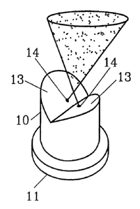
Fig. 3 shows the nozzle schematically in pers-
pective under use.

DESCRIPTION OF EMBODIMENT
The nozzle in Fig. 1-3 is made of a metallic cylinder 10
with mounting flange 11 formed through turning. The end of
the cylinder closest to the flange exhibits a concentric
turned space 12. The opposite end of the cylinder is pro-
vided with two towards each other inclining plane surfaces
13, sloping towards the longitudinal axis of the cylinder,
with a mutual divergent angle. The angle between said plane
surfaces can be between 70 and 1400.

A beam channel 14 is bored in each plane surf ace 13, sub-
stantially perpendicular to each plane surface. The two
channels 14 are consequently drilled with such a mutual
angle a that they converge towards a point outside the
nozzle. The angle a between both beam channels is between 70
and 140 and channels extend into the space 12. Each channel
14 has a diameter b of 0.5-1.5 mm and the distance a between
the downstream mouth of the beam channels is 2-5 mm.
The nozzle is used mounted on the outlet from a mixing
chamber on the spray-gun, which mixing chamber is fed with
plastic and hardener via separate feed channels. Mixture of
plastic and hardener should have a viscosity between 150 and
75.000 cpois and feed pressure is suitably between 75 and
100 bar.


CA 02232619 1998-03-20
WO 97/11784 PCT/SE96/01197
4
The nozzle with this equipment can be used, e.g. in combina-
tion with the nozzles for feeding cut reinforcement fibres,
to spray composite laminate directly in a mould, for exam-
ple, by means of an industrial robot. The nozzle can also be
used without addition of fibres, to cover a surface with a
layer of thermosetting plastic, for example a floor area.
The spray image has a narrow elliptical form with distinct
edges.

The invention is not limited to the above described embodi-
ment, but variants may occur within the scope of the at-
tached claims. For instance the nozzle may be equipped with
more than two spray channels. By using more spray channels
the spray image can be affected.

Dessin représentatif
Une figure unique qui représente un dessin illustrant l'invention.
États administratifs

Pour une meilleure compréhension de l'état de la demande ou brevet qui figure sur cette page, la rubrique Mise en garde , et les descriptions de Brevet , États administratifs , Taxes périodiques et Historique des paiements devraient être consultées.

États administratifs

Titre Date
Date de délivrance prévu 2009-05-12
(86) Date de dépôt PCT 1996-09-24
(87) Date de publication PCT 1997-04-03
(85) Entrée nationale 1998-03-20
Requête d'examen 2002-10-21
(45) Délivré 2009-05-12
Expiré 2016-09-26

Historique d'abandonnement

Il n'y a pas d'historique d'abandonnement

Historique des paiements

Type de taxes Anniversaire Échéance Montant payé Date payée
Le dépôt d'une demande de brevet 300,00 $ 1998-03-20
Enregistrement de documents 100,00 $ 1998-09-09
Taxe de maintien en état - Demande - nouvelle loi 2 1998-09-24 50,00 $ 1998-09-11
Taxe de maintien en état - Demande - nouvelle loi 3 1999-09-24 50,00 $ 1999-07-21
Taxe de maintien en état - Demande - nouvelle loi 4 2000-09-25 50,00 $ 2000-09-18
Taxe de maintien en état - Demande - nouvelle loi 5 2001-09-24 75,00 $ 2001-09-24
Taxe de maintien en état - Demande - nouvelle loi 6 2002-09-24 150,00 $ 2002-09-20
Requête d'examen 400,00 $ 2002-10-21
Taxe de maintien en état - Demande - nouvelle loi 7 2003-09-24 150,00 $ 2003-09-19
Taxe de maintien en état - Demande - nouvelle loi 8 2004-09-24 200,00 $ 2004-09-15
Taxe de maintien en état - Demande - nouvelle loi 9 2005-09-26 200,00 $ 2005-09-06
Taxe de maintien en état - Demande - nouvelle loi 10 2006-09-25 250,00 $ 2006-09-11
Expiré 2019 - Paiement rectificatif/L'article 78.6 225,00 $ 2007-01-18
Taxe de maintien en état - Demande - nouvelle loi 11 2007-09-24 250,00 $ 2007-09-05
Taxe de maintien en état - Demande - nouvelle loi 12 2008-09-24 250,00 $ 2008-09-05
Taxe finale 300,00 $ 2009-02-24
Taxe de maintien en état - brevet - nouvelle loi 13 2009-09-24 250,00 $ 2009-09-11
Taxe de maintien en état - brevet - nouvelle loi 14 2010-09-24 250,00 $ 2010-08-31
Taxe de maintien en état - brevet - nouvelle loi 15 2011-09-26 450,00 $ 2011-08-23
Taxe de maintien en état - brevet - nouvelle loi 16 2012-09-24 450,00 $ 2012-09-06
Taxe de maintien en état - brevet - nouvelle loi 17 2013-09-24 450,00 $ 2013-09-12
Taxe de maintien en état - brevet - nouvelle loi 18 2014-09-24 450,00 $ 2014-09-08
Taxe de maintien en état - brevet - nouvelle loi 19 2015-09-24 450,00 $ 2015-09-11
Titulaires au dossier

Les titulaires actuels et antérieures au dossier sont affichés en ordre alphabétique.

Titulaires actuels au dossier
APLICATOR SYSTEM AB
Titulaires antérieures au dossier
SAND, KJELL
Les propriétaires antérieurs qui ne figurent pas dans la liste des « Propriétaires au dossier » apparaîtront dans d'autres documents au dossier.
Documents

Pour visionner les fichiers sélectionnés, entrer le code reCAPTCHA :


Pour visualiser une image, cliquer sur un lien dans la colonne description du document. Pour télécharger l'image (les images), cliquer l'une ou plusieurs cases à cocher dans la première colonne et ensuite cliquer sur le bouton "Télécharger sélection en format PDF (archive Zip)" ou le bouton "Télécharger sélection (en un fichier PDF fusionné)".

Liste des documents de brevet publiés et non publiés sur la BDBC .

Si vous avez des difficultés à accéder au contenu, veuillez communiquer avec le Centre de services à la clientèle au 1-866-997-1936, ou envoyer un courriel au Centre de service à la clientèle de l'OPIC.


Description du
Document 
Date
(yyyy-mm-dd) 
Nombre de pages   Taille de l'image (Ko) 
Dessins représentatifs 1998-06-30 1 7
Abrégé 1998-03-20 1 49
Dessins 1998-03-20 1 16
Revendications 1998-03-20 1 34
Description 1998-03-20 4 136
Page couverture 1998-06-30 1 44
Dessins représentatifs 2008-03-31 1 5
Description 2006-07-11 6 192
Revendications 2006-07-11 3 85
Revendications 2007-05-04 3 92
Description 2007-05-04 6 194
Description 2008-01-23 6 196
Revendications 2008-01-23 3 97
Page couverture 2009-04-17 1 36
Correspondance 1998-09-09 2 58
Cession 1998-09-09 2 70
Cession 1998-03-20 2 97
PCT 1998-03-20 10 334
Correspondance 1998-06-09 1 29
Poursuite-Amendment 2002-10-21 1 27
Poursuite-Amendment 2003-03-17 1 33
Poursuite-Amendment 2008-01-23 6 197
Poursuite-Amendment 2006-01-11 2 65
Poursuite-Amendment 2006-07-11 8 227
Poursuite-Amendment 2006-11-06 2 56
Poursuite-Amendment 2007-01-18 1 38
Correspondance 2007-01-26 1 14
Poursuite-Amendment 2007-05-04 5 171
Poursuite-Amendment 2007-07-23 2 43
Correspondance 2009-02-24 1 30
Taxes 2009-09-11 1 31
Taxes 2011-08-23 1 34
Taxes 2012-09-06 1 30