Sélection de la langue

Search

Sommaire du brevet 2232892 

Énoncé de désistement de responsabilité concernant l'information provenant de tiers

Une partie des informations de ce site Web a été fournie par des sources externes. Le gouvernement du Canada n'assume aucune responsabilité concernant la précision, l'actualité ou la fiabilité des informations fournies par les sources externes. Les utilisateurs qui désirent employer cette information devraient consulter directement la source des informations. Le contenu fourni par les sources externes n'est pas assujetti aux exigences sur les langues officielles, la protection des renseignements personnels et l'accessibilité.

Disponibilité de l'Abrégé et des Revendications

L'apparition de différences dans le texte et l'image des Revendications et de l'Abrégé dépend du moment auquel le document est publié. Les textes des Revendications et de l'Abrégé sont affichés :

  • lorsque la demande peut être examinée par le public;
  • lorsque le brevet est émis (délivrance).
(12) Brevet: (11) CA 2232892
(54) Titre français: ENSEMBLE DE COUVERCLE POUR BATTERIE RECTANGULAIRE
(54) Titre anglais: CAP ASSEMBLY FOR RECTANGULAR BATTERY
Statut: Périmé
Données bibliographiques
(51) Classification internationale des brevets (CIB):
  • H01M 2/34 (2006.01)
  • H01M 2/04 (2006.01)
  • H01M 2/12 (2006.01)
  • H01M 2/02 (2006.01)
  • H01M 2/10 (2006.01)
(72) Inventeurs :
  • KIM, CHANG-SEOB (Republique de Corée)
(73) Titulaires :
  • SAMSUNG DISPLAY DEVICES CO. LTD. (Republique de Corée)
(71) Demandeurs :
  • SAMSUNG DISPLAY DEVICES CO. LTD. (Republique de Corée)
(74) Agent: RIDOUT & MAYBEE LLP
(74) Co-agent:
(45) Délivré: 2001-01-23
(22) Date de dépôt: 1998-03-20
(41) Mise à la disponibilité du public: 1999-03-29
Requête d'examen: 1998-03-20
Licence disponible: S.O.
(25) Langue des documents déposés: Anglais

Traité de coopération en matière de brevets (PCT): Non

(30) Données de priorité de la demande:
Numéro de la demande Pays / territoire Date
97-49748 Republique de Corée 1997-09-29

Abrégés

Abrégé français

Ensemble de couvercle pour batterie rectangulaire composé d'un couvercle dans lequel est formé un évent, une borne d'électrode positive percée d'un trou de passage menant au trou de décharge et se combinant à la partie supérieure du couvercle. Une plaque isolée est intercalée entre eux, une languette d'électrode positive est raccordée à l'électrode positive d'un ensemble d'électrode, un support d'évent de sûreté conducteur avec dépassement de rivets creux traverse l'évent du couvercle ainsi que le trou de la borne d'électrode positive de façon à être couplé à la borne d'électrode positive. Un évent de sûreté conducteur conique a une partie circonférentielle supérieure qui se combine à la surface inférieure du support de l'évent de sûreté de façon à sceller le creux du dépassement de rivets. Le sommet de cet évent de sûreté conducteur conique vient en contact avec la surface supérieure de la languette d'électrode positive, et le sommet de l'évent de sûreté se sépare de la languette d'électrode positive puis l'évent de sûreté est détruit lorsque la pression interne de la batterie augmente à un niveau préétabli.


Abrégé anglais


There is provided a cap assembly for a rectangular battery comprising a
cap cover in which a vent hole is formed, a positive electrode terminal which has a
through hole leading to the discgarge hole and combines with the upper portion of
the cap cover having an insulating plate interposed therebetween, a positive
electrode tab connected to a positive electrode of an electrode assembly, a
conductive safety vent support having a hollow rivet protrusion passing through the
vent hole of the cap cover and the through hole of the positive electrode terminal
to be coupled to the positive electrode terminal, and a conic conductive safety
vent whose upper circumferential portion combines with the bottom surface of thesafety vent support to seal the hollow of the rivet protrusion, and whose vertexcontacts the upper surface of the positive electrode tab, wherein the vertex of the
safety vent separates from the positive electrode tab and the safety vent is
destroyed when the internal pressure of the battery increases to a predeterminedlevel.

Revendications

Note : Les revendications sont présentées dans la langue officielle dans laquelle elles ont été soumises.


What is claimed is:

1. A cap assembly for a rectangular battery comprising:
a cap cover in which a vent hole is formed;
a positive electrode tab connected to a positive electrode of an electrode
assembly,
a conductive safety vent support having a hollow rivet protrusion passing
through said vent hole of said cap cover; and
a conductive safety vent whose upper circumferential portion combines with
the bottom surface of said safety vent support to seal the hollow of said rivet
protrusion, and whose vertex contacts the upper surface of said positive electrode
tab,
wherein said vertex of said safety vent separates from said positive electrode
tab and said safety vent is destroyed when the internal pressure of said batteryincreases to a predetermined level.
2. The cap assembly for a rectangular battery as claimed in claim 1,
wherein said vertex attaches to the upper surface of said positive electrode tab by a
laser welding.
3. The cap assembly for a rectangular battery as claimed in claim 1, further
comprising:
a tab fixing portion combined with the upper surface of said positive electrode
tab, and having a through hole leading to said vent hole formed therein and a hooking
portion formed at upper edge thereof; and
a support having a combining portion with which said hooking portion
combines, and a through hole leading to said vent hole, formed therein.
4. The cap assembly for a rectangular battery as claimed in claim 1,
wherein said safety vent has the conic shape.
5. The cap assembly for a rectangular battery as claimed in claim 1, further
comprising a positive electrode terminal which has a through hole leading to said vent
hole and combines with the upper portion of said cap cover having an insulating plate
interposed therebetween.

Description

Note : Les descriptions sont présentées dans la langue officielle dans laquelle elles ont été soumises.

CA 02232892 1998-03-20


CAP ASSEMBLY FOR REC:TANGULAR BATTERY


BACKGROUND OF THE INVENTION
Field of the Invention
The present invention relates to a cap assembly for a rectangular battery,
and more particularly, to a cap assembly for a rectangular battery wherein powercan be cut off simultaneously when a safety vent is broken due to an increase ininternal pressure of a battery.
Description of Related Art
A rectangular battery has been widely used as a secondary battery, and
contains an electrode assembly in a rectangular case. FIG. 1 shows an example
of the rectangular battery. As shown in FIG. 1, a cylindrical or rectangular
electrode assembly (not shown), called a jelly-roll, is installed inside a rectangular
case 1 having an open upper surface. The jelly-roll is formed by winding anode
and cathode plates (not shown) with a separator (not shown) being interposed
therebetween as an insulator. A cap assembly 10 is installed at the upper portion
of the case 1.
The cap assembly 10 includes a positive electrode portion 11, a negative
electrode portion 12 and an insulating plate 13 for electrically insulating the
positive and negative electrode portions 11 and 12 from each other.
When the rectangular battery reacts abnormally, the internal pressure in the
case 1 increases due to generation of a gas, so the case 1 may be exploded.
Thus, in order to prevent that kind of explosion and reduce the internal pressure in
the case 1, a fracture portion 14 for discharging a gas generated during the
reaction is formed at the negative electrode portion 12. That is, when the internal
pressure of the battery increases, the edges, which is weak in rigidity, of the
fracture portion 14 is destroyed to form a safety vent through which the generated
gas is discharged.
In the conventional cap assembly, thle internal pressure of the battery can
be reduced by destroying the fracture portic~n 14, but the flow of current is not
blocked off. Therefore, a short circuit or an electric leakage can be generated

CA 02232892 1998-03-20


after breakdown of the fracture portion.

SUMMARY OF THE INVENTION
To solve the above problem, an object of the present invention is to provide
an improved cap assembly for a rectangular battery in which current is cut
5 simultaneously with the discharge of a gas to reduce the internal pressure of a
battery.
To accomplish the above object, there is provided a cap assembly for a
rectangular battery comprising a cap cover in which a vent hole is formed; a
positive electrode tab connected to a positive electrode of an electrode assembly;
a conductive safety vent support having a hollow rivet protrusion passing
through said vent hole of said cap cover; and a conductive safety vent whose
upper circumferential portion combines witlh the bottom surface of said safety vent
support to seal the hollow of said rivet protrusion, and whose vertex contacts the
upper surface of said positive electrode tab, wherein said vertex of said safetyvent separates from said positive electrode tab and said safety vent is destroyed
when the internal pressure of said battery increases to a predetermined level.

BRIEF DESCRIPTION OF THE DRAWINGS
The above object and advantage of the present invention will become more
apparent by describing in detail a preferred embodiment thereof with reference to
the attached drawings in which:
FIG. 1 is a sectional view schematic:ally showing a rectangular battery
having a conventional cap assembly;
FIG. 2 is an exploded perspective view of a rectangular battery having a
cap assembly according to the present invention;
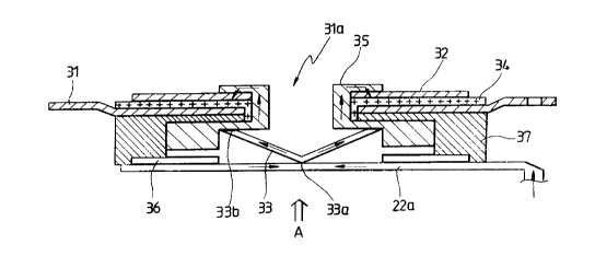
FIG. 3 is a sectional view of the cap assembly according to the present
invention; and
FIG. 4 is the cap assembly of FIG. :3 viewed from the perspective of "A" in
FIG. 3.

DETAILED DESCRIPTION OF THE INVENTION

CA 02232892 l998-03-20


Referring to FIG. 2, a rectangular battery having a cap assembly according
to the present invention includes an electrode assembly 22 formed in a rectangular
case 21 by winding anode and cathode plates, which are coated by an active
material, with a separator which is made of a porous polymer film, being
interposed therebetween; and a cap assembly 30 combined on the upper portion
of the case 21. An insulating plate 23 is inl:erposed between the electrode
assembly 22 and the cap assembly 30. The cap assembly 30 is electrically
connected by a positive electrode tab 22a, which penetrates the insulating plate 23
and connects to a positive electrode of the electrode assembly 22, and a negative
electrode tab 22b.
Referring to FIGS. 3 and 4 showing the configuration of the cap assembly
30 in detail, the cap assembly 30 includes a cap cover 31 in which a vent hole
31a is formed; a positive electrode terminal 32 formed over the cap cover 31; and
a conic conductive safety vent 33 whose upper circumferential portion is combined
with the bottom surface of a safety vent support 35 to seal the discgarge hole 31a.
The vertex 33a of the safety vent 33 is combined in contact with the upper surface
of the positive electrode tab 22a. At this tirne, it is preferable that a welding
portion (W1) between the vertex 33a and the positive electrode tab 22a is weldedby a laser. As will be described later, when the internal pressure of the battery
increases, the vertex 33a is disconnected from the positive electrode tab 22a toprevent current from flowing.
The cap assembly 30 can further include a tab fixing portion 36 for
supporting the positive electrode tab 22a to prevent the positive electrode tab 22a
from being pulled and damaged when the vertex 33a is separated from the
positive electrode tab 22a; and a support 37 for supporting the tab fixing portion
36. The tab fixing portion 36 is combined with a welding portion (W2) on the
upper surface of the positive electrode tab :22a by a laser welding method. A
hooking portion 36a formed on the tab fixing portion 36 hangs on a combining
portion 37a formed in the support 37, thereby retaining the tab fixing portion 36.
The tab fixing portion 36 and the support 37 have through holes 36b and
37b leading to the vent hole 31a of the cap cover 31, respectively. An insulating
plate 34 lies interposed between the cap cover 31 and the positive electrode

CA 02232892 l998-03-20


terminal 32.
Also, a conductive safety vent support 35 is provided to more safely
combine the safety vent 33. The safety vent support 35 has a rivet protrusion 35a
through which a hollow is formed being connected to the vent hole 31a of the capcover 31. The rivet protrusion 35a inserts into the through hole 37b of the support
37, the vent hole 31a of the cap cover 31, the through hole 34a of the insulating
plate 34, and the through hole 32a of the positive electrode terminal 32, and then
is pressed flat using a press or another tools. In the case that the safety ventsupport 37 is employed, the upper circumferential portion 33b of the safety vent 33
combines with the bottom surface of the safety vent support 35 to seal the hollow
of the rivet protrusion 35a. A welding portion (W3) between the upper portion ofthe safety vent 33 and the safety vent support 35 is welded using a laser.
In the operation of the rectangular battery, current flows toward the positive
electrode terminal 32 via the positive electrode tab 22a, the safety vent 33 and the
safety vent support 35, as shown in FIG. 3. When the battery is charged or
discharged, the temperature inside the battery increases due to conditions such as
overcurrent, overcharge, etc. Accordingly, a gas is generated from a chemical
material including an electrolyte, thus increasing the internal pressure of the
battery. At this time, the safety vent 33 is pressed by pressure of the gas
generated inside the battery.
When the internal pressure of the b;attery increases to a predetermined
level or higher, the welding portion (W1) between the vertex 33a of the safety vent
33 and the positive electrode tab 22a is destroyed, so that the safety vent 33
separates from the positive electrode tab 22a. Therefore, the flow of current isstopped. At this time, the positive electrode tab 22a can be safely maintained
since it is supported by the tab fixing portion 36.
When the internal pressure of the biattery increases more and more, the
safety vent 33 made of a thin plate is broken, so that the gas in the battery isdischarged to outside the battery via the vent hole 31a. Thus, the internal
pressure of the battery is reduced.
According to the cap assembly 30 fi~r the rectangular battery of the present
inven~ion, when the internal pressure of the battery increases excessively, the

CA 02232892 1998-03-20


conic safety vent 33 is destroyed to thereby discharge a gas in the battery and
prevent flow of current. Therefore, the safety of a battery can be guaranteed, so
that an over current or leakage can be prevented.

Dessin représentatif
Une figure unique qui représente un dessin illustrant l'invention.
États administratifs

Pour une meilleure compréhension de l'état de la demande ou brevet qui figure sur cette page, la rubrique Mise en garde , et les descriptions de Brevet , États administratifs , Taxes périodiques et Historique des paiements devraient être consultées.

États administratifs

Titre Date
Date de délivrance prévu 2001-01-23
(22) Dépôt 1998-03-20
Requête d'examen 1998-03-20
(41) Mise à la disponibilité du public 1999-03-29
(45) Délivré 2001-01-23
Expiré 2018-03-20

Historique d'abandonnement

Il n'y a pas d'historique d'abandonnement

Historique des paiements

Type de taxes Anniversaire Échéance Montant payé Date payée
Requête d'examen 400,00 $ 1998-03-20
Enregistrement de documents 100,00 $ 1998-03-20
Le dépôt d'une demande de brevet 300,00 $ 1998-03-20
Taxe de maintien en état - Demande - nouvelle loi 2 2000-03-20 100,00 $ 2000-01-26
Taxe finale 300,00 $ 2000-10-12
Taxe de maintien en état - brevet - nouvelle loi 3 2001-03-20 100,00 $ 2001-03-20
Taxe de maintien en état - brevet - nouvelle loi 4 2002-03-20 100,00 $ 2002-02-18
Taxe de maintien en état - brevet - nouvelle loi 5 2003-03-20 150,00 $ 2003-02-18
Taxe de maintien en état - brevet - nouvelle loi 6 2004-03-22 150,00 $ 2003-12-22
Taxe de maintien en état - brevet - nouvelle loi 7 2005-03-21 200,00 $ 2005-02-08
Taxe de maintien en état - brevet - nouvelle loi 8 2006-03-20 200,00 $ 2006-02-07
Taxe de maintien en état - brevet - nouvelle loi 9 2007-03-20 200,00 $ 2007-02-08
Taxe de maintien en état - brevet - nouvelle loi 10 2008-03-20 250,00 $ 2008-02-08
Taxe de maintien en état - brevet - nouvelle loi 11 2009-03-20 250,00 $ 2009-02-12
Taxe de maintien en état - brevet - nouvelle loi 12 2010-03-22 250,00 $ 2010-02-18
Taxe de maintien en état - brevet - nouvelle loi 13 2011-03-21 250,00 $ 2010-12-24
Taxe de maintien en état - brevet - nouvelle loi 14 2012-03-20 250,00 $ 2011-12-16
Taxe de maintien en état - brevet - nouvelle loi 15 2013-03-20 450,00 $ 2013-01-15
Taxe de maintien en état - brevet - nouvelle loi 16 2014-03-20 450,00 $ 2014-01-08
Taxe de maintien en état - brevet - nouvelle loi 17 2015-03-20 450,00 $ 2014-12-10
Taxe de maintien en état - brevet - nouvelle loi 18 2016-03-21 450,00 $ 2016-02-24
Taxe de maintien en état - brevet - nouvelle loi 19 2017-03-20 450,00 $ 2017-03-02
Titulaires au dossier

Les titulaires actuels et antérieures au dossier sont affichés en ordre alphabétique.

Titulaires actuels au dossier
SAMSUNG DISPLAY DEVICES CO. LTD.
Titulaires antérieures au dossier
KIM, CHANG-SEOB
Les propriétaires antérieurs qui ne figurent pas dans la liste des « Propriétaires au dossier » apparaîtront dans d'autres documents au dossier.
Documents

Pour visionner les fichiers sélectionnés, entrer le code reCAPTCHA :


Pour visualiser une image, cliquer sur un lien dans la colonne description du document. Pour télécharger l'image (les images), cliquer l'une ou plusieurs cases à cocher dans la première colonne et ensuite cliquer sur le bouton "Télécharger sélection en format PDF (archive Zip)" ou le bouton "Télécharger sélection (en un fichier PDF fusionné)".

Liste des documents de brevet publiés et non publiés sur la BDBC .

Si vous avez des difficultés à accéder au contenu, veuillez communiquer avec le Centre de services à la clientèle au 1-866-997-1936, ou envoyer un courriel au Centre de service à la clientèle de l'OPIC.


Description du
Document 
Date
(yyyy-mm-dd) 
Nombre de pages   Taille de l'image (Ko) 
Page couverture 1999-04-16 2 70
Abrégé 1998-03-20 1 26
Description 1998-03-20 5 204
Revendications 1998-03-20 1 43
Dessins 1998-03-20 4 55
Dessins représentatifs 2001-01-04 1 10
Page couverture 2001-01-04 2 71
Dessins représentatifs 1999-04-16 1 10
Taxes 2000-01-26 1 33
Cession 1998-03-20 4 130
Correspondance 2000-10-12 1 50
Taxes 2001-03-20 1 32